
Aijia Yao
MIT EECS • HTMAA 2025
Week 6 – Electronics Production
October 2025
This week was mainly about PCB production.
What I Did
- Follow this link to the group assignment.
- Learning design tools for PCB production, particularly milling copper board.
PCB Design
- Before milling the PCB, I reviewed my design from last week of a simple PCB with XIAO-RP2040 microcontroller and RGB LEDs.
| Component | Specification |
|---|---|
| Microcontroller | XIAO-ESP32-S3(simulation);XIAO-RP2040(real design) |
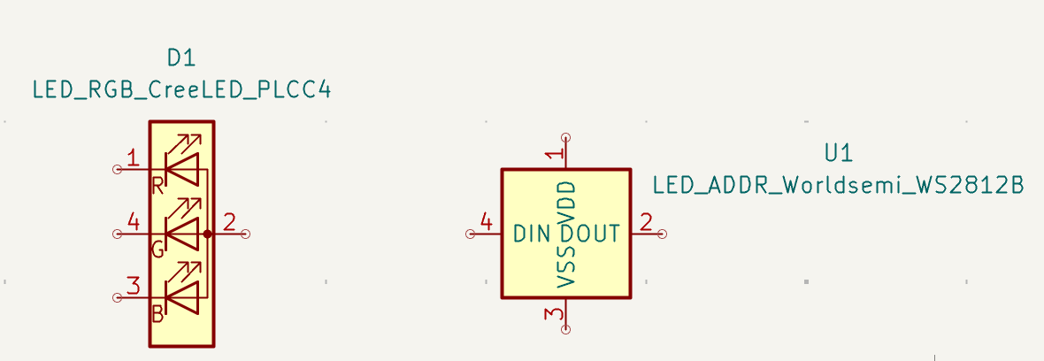
| LED | NeoPixel Compatible LED (WS2812B, see datasheet) |
| Button | Tactile switch (TS04-66-43-BK-260-SMT, see datasheet) |
PCB Milling
Then I milled the PCB using Bantam Othermill. The process is quite straightforward.
- First, I secured the copper board on the milling bed with double-sided tape.
- Next, I loaded the .gbr file into the software and set the origin point.
- After that, I just needed to press "Start" and change the milling tool if necessary, then just wait for it to finish.
- (The whole process took around 10 minutes)

Other Notes
- The gerber files for copper layer is here and the edge cuts is here.
- After debugging with a multimeter, I confirmed that all connections were correct and the circuit was functioning as intended. The full play around with this PCB is discussed in Output Device Week.