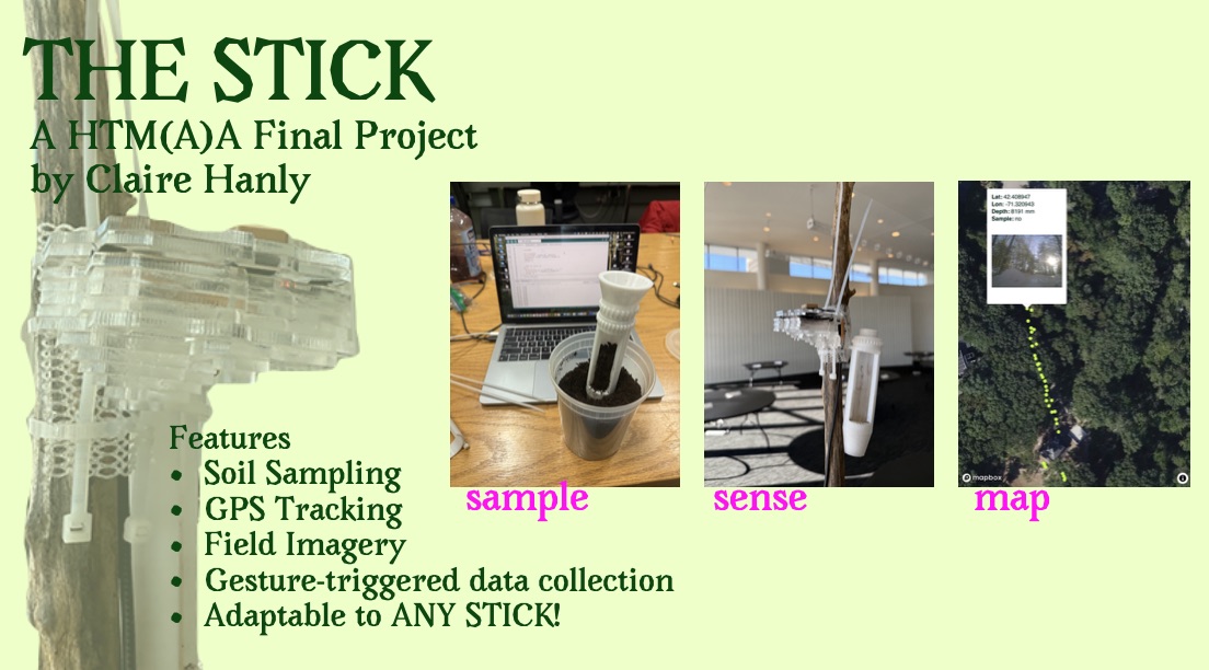
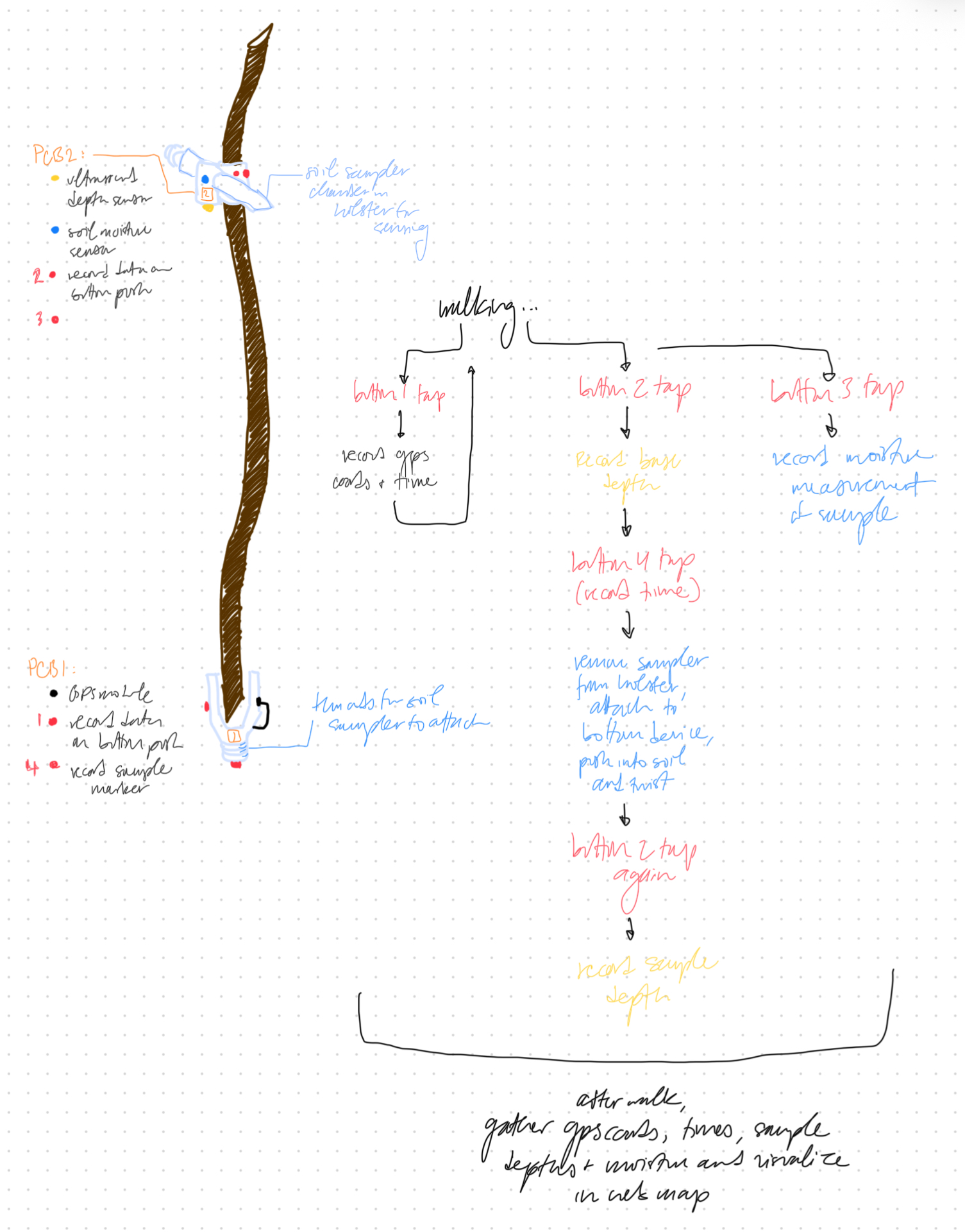
My project, affectionately known as "the stick" even though the stick itself is the only component not related to the material of this course, is a modular walking soil sensor apparatus. It includes an electronic assembly with location, image, capacitance, depth, and acceleration sensing components that allows the user to capture data about a field excursion based on gestures with the stick: a single tap records GPS coordinates, and a double tap records an image. When the stick is turned downwards to attach or detach its soil sampling attachment, a flag is recorded to look for changes in depth and capacitance data. All of this information can be visualized in a web map describing the walk.
What has been done? Why?
The precedents and justification for this approach are elaborated under "Initial Project Objectives" and "Project Background and Ideation" below, but its primary motivation is to allow highly mobile and low-impact soil sensing through a device that can collect data from anywhere, without requiring permanent installation.
What did I design? With what materials, at what cost?
I designed a custom PCB with the sensing components as well as the 3D printed and laser cut elements of the final device integration. I relied heavily on the example material provided for the course as well as some external examples such as this one for tap detection and this one for soil sampling equipment.
The materials and components I used, as well as their prices, are described in the bill of materials. Processes used to assemble them include PCB milling, soldering, 3D Printing, laser cutting, embedded programming, and a good amount of gluing.
What did it achieve?
The final product achieved its goal of recording soil samples and relevant geolocated data, with some limitations that I hope to address in future versions. These include more carefully calibrating the gesture detection, connecting the raw capacitance measurements to actual soil moisture values, testing the depth sensor with underground sensing on non-frozen soil, and improving the integration of GPS and camera sensing, which have some timing conflicts. However, I evaluated the stick by bringing it for a walk and was happy with the results.
Here is a short video from that walk:
And a summary slide explaining the device:
Production is explained in much more detail in the next section. Thank you for a great semester!
////////////////////////////////////
The below information is the journal of ideas and inspiraitons accumulated across the semester. It starts with the midterm materials, then the production of the device across the weeks I worked on it, and then some background and ideation from the very beginning of the year.
[Midterm] System Diagram and TO-DO
Below is a diagram of the slean-elagh device as it is designed ahead of Midterm week, November 19th.
And following are the tasks that remain to be done:
Design and print stick-attachment (cuff) components for upper and lower device
Design and print PCB housings for upper and lower device
Design and print final peat corer and holster for upper device
Design and print final PCBs for upper and lower devices, with sensors attached
Test lower device (walking GPS capture)
Test upper device (depth and moisture sensing)
Network devices together; finalize data pipeline for visualization
Produce map visualization on web; determine if this can be live?
Final documentation: video
Final documentation: web
These are discussed further in the development tracking schedule below:
Device Development Tracking
Here is my documentation of weekly progress and my schedule of deliverables to the finish line:
October 15
In Week 6, I milled a PCB to hold the components of the
Upper Device
. As a first pass, this just held a Pico W and a button, but it has rooms for pinheads that can attach other components including the GPS. This PCB will accumulate components across the subsequent assignments and serves as a prototype for the final project Upper Device, which I expect to have to remake even though I hope not to.
October 29
In Week 8, I added a GPS module to my PCB and tested it to ensure that it is sensing locations accurately.
It does this in an ongoing, serial way as long as the GPS is plugged in, but for my purposes I want to filter out these measurements to only record them when the walking stick contacts the ground. I wrote some additional code to record GPS locations only when a button is pushed. I am still a bit unclear about how this will work with a device that needs to be mobile, however. Do I need to save all these values in a list while disconnected from the computer, and then upload them to a web interface? Or do I somehow transmit them to the computer directly, using this button behavior? What will power the microcontroller while I'm walking? To be evaluated in the coming weeks...
November 6
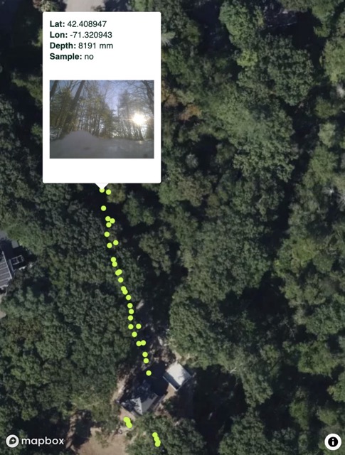
In Week 9 I first added functionality to my PCB so that it would print GPS coordinates to the Serial Monitor at the push of a button. This enabled me to control the frequency of the sensing, which was overwhelming without any kind of filter. Next, I started experimenting with how to actually *record* that information, since printing to the Serial Monitor was not enabling me to consolidate a walk into a single list. To do this, I updated my Arduino sketch to write the coordinates to the Pico W's flash memory, and then dump them out to Serial when the walk is done. However, this still has the limitation ultimately of copy-pasting from the Serial Monitor. I hope to improve on this next week, through the networking assignment. Below is my first recorded walk, using the current method:
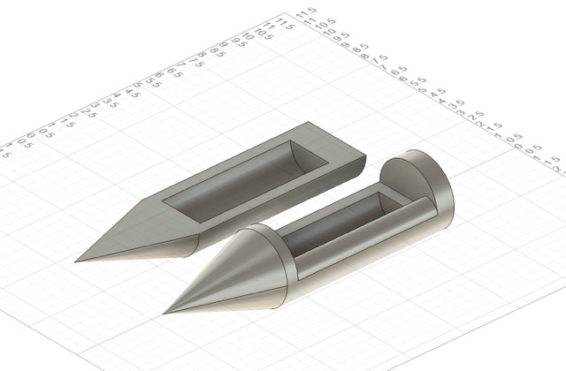
The other progress I made this week was towards developing my soil sampling device. I started out by designing and 3D printing two simple prototypes: one with absolute minimum features and a flat profile, and one with a round profile and a small wing to try to capture the soil sample better.
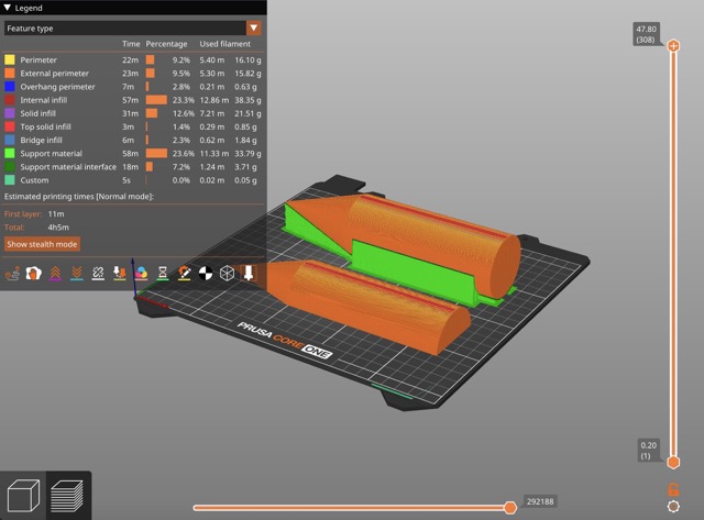
After designing these in Fusion, I sliced them and 3D Printed them in white PLA. The print took about 4.5 hours.
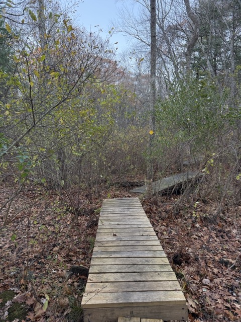
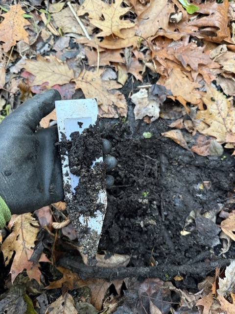
Then, I took them on a walk in the woods. I went down the trail near my house and stopped at a marshy area of the woodland, where the ground would be soft and boggy.
I tested each of the corers in a different area of the soil, and evaluated the sample it took. The samples are meant to be withdrawn by pushing the sharp end of the corer into the dirt, and then spinning it around to capture some soil in the reservoir area of the corer.
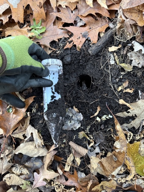
Neither of them performed as I wanted-- what I'm shooting for is more like the USGS reference below:
In fairness, their soil is much more moist than mine was, so it made a cleaner sample. I think, while I hoped that the curved sampler would perform better, it ended up putting to big ofa hole in the soil as it entered the ground, making it impossible to reach the sample around it. In the next iterations, I will refine the flat version to be longer and have sharper edges that can capture the soil better. I was pleased to note that the PLA was sharp and strong, so I think it will be a sufficiently robust material for this task.
November 12
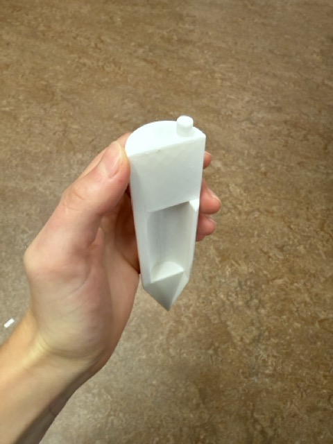
Based on last week's experience, I made a new prototype of my corer, which features a mostly flat profile with a little fin that will help guide the soil into the reservoir. I printed a dot on the top to indicate that it should spin in this direction (clockwise) to fill the fin.
I hope to test this soon as the ground is rapidly freezing!
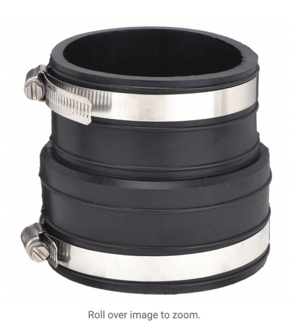
Separately, I have been thinking about how my device will attach to the stick. I think the best part to imitate would be a flexible plumbing coupling like this:
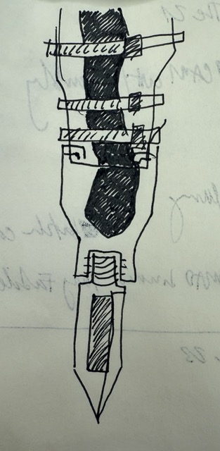
I also found another reference with more cuffs that seems like it would be helpful for attaching well to a stick. I imagine that the bottom of this could have holes that correspond to bumps or "buttons" on the rigid part of the lower device.
This is somewhat how I imagine it:
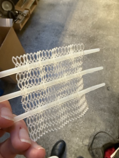
I want to experience with making a "knitted" looking PETG cuff for the grippy part, and I found some plumbing parts at home (thanks contractors) to test with.
November 19
This is "machine week" and things have been busy. In my midterm discussion with Anthony we decided to condense the electronics into a single PCB rather than having an "upper device" and a lower device. This is because doing the fine-tuning of mechanical elements to translate a tap on the ground into a button push isn't worth the convenience of programming a button; rather, we can detect taps in the upper device using an accelerometer and consolidate all the sensing up there.
I have started printing some attachment elements, and I am excited about this TPU mesh that I made-- it will help with attaching to the stick adjustably, because it creates a matrix for attaching elements vertically and horizontally with zip ties, and it provides traction against the stick:
Even with the electronics consolidated at the top of the stick, I still need an element at the bottom of the stick to hold the sampling end. This mesh will help me attach both.
November 26
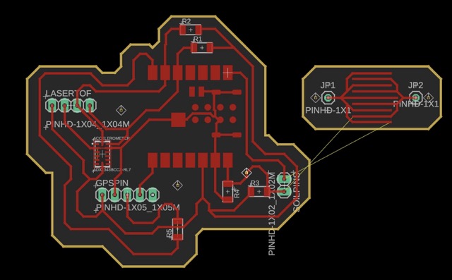
This week I worked on redesigning my PCB to contain the electronic elements for the "upper device" which will now have all the electronics on it. It includes an ESP32 S3 Sense module (with a camera and SD card) as the microcontroller and to capture image data; an MPU6050 accelerometer to capture gesture data, a VL53L0X laser time of flight sensor for depth readings, the GT-U7 GPS module I have been using thus far, and a small homemade capacitive sensor.
Above is the PCB visualization for the final board.
And the corresponding schematic.
December 3
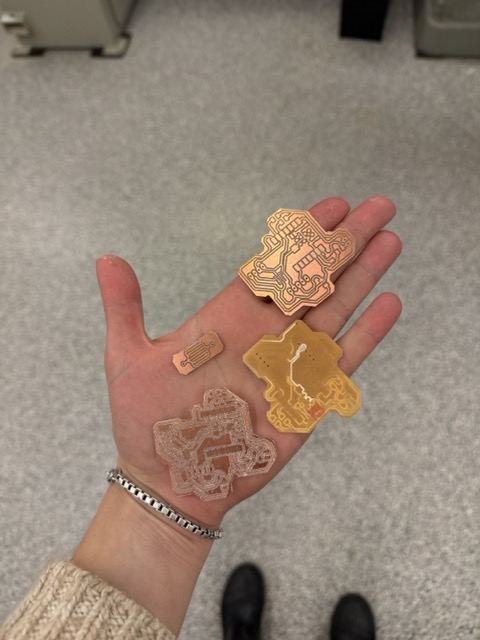
This week I milled the final PCB, soldered the components onto it, and started testing. I spent an entire afternoon with the PCB mill and after two failures (see below-- one dull 1/32" bit and another copper plate that came off the bed), I milled a board to the necessary standard.
Next, I attached all the components. This was delicate because it involved using solder paste to attach the accelerometer and a clamp to get the wires for the capacitive sensor right.
With this I was ready to start testing.
December 5
I tested the electronics using a dedicated sketch for each piece. My files are linked, with their sources.
In the course of testing, I discovered that my accelerometer was soldered wrong (not connected to power because I had moved traces), and I had to attach one on a breakout board. For ease of assembly, I preferred this anyway, even though it took up more space.
I then wrote my stick_integration sketch to bring all the components together. This included tap detection based on this example (I simplified this by removing the state machine and only triggering serial on tap of any magnitude) as well as bringing in the other data components and writing them to a CSV on the SD card. I used ChatGPT to help me debug my integration (conversation).
December 10
With working electronics, I moved to assembly. In order to intregrate another manufacturing process, I decided to laser cut (subtractive) the PCB holder that would lock into my TPU mesh (additive). I designed this in fusion and cut it from 1/8" acrylic:
I made sure to include holes and voids where the electronic components would go (based on a fusion mesh of my actual PCB), so that the whole assembly would pass the "shake test":
Once I had cut all the components from acrylic, I used vertical zip ties to register all the parts together and super glued them. To hold the electronics in place, I used some strategically placed hook-and-loop patches so that things would stay put when I was testing but still come apart easily in case of an issue.
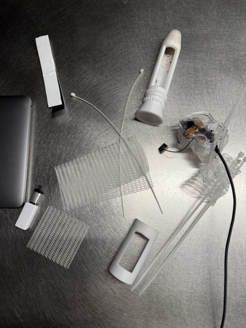
I removed and wove the vertical zip ties through the mesh to hold the electronics onto the stick; it then attached using horizontal zip ties looping through the same mesh. All the components are visible in this flat-lay:
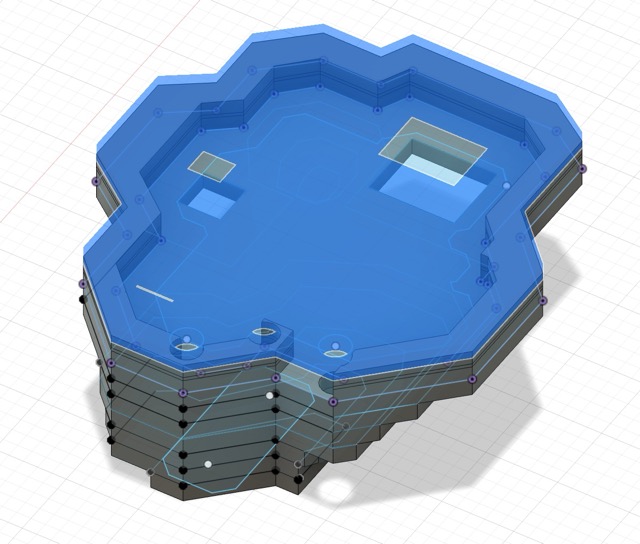
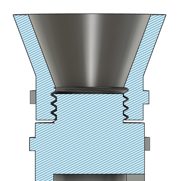
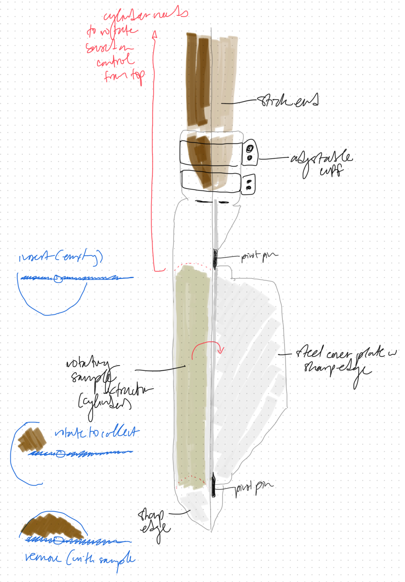
For the soil corer final version, I was inspired by this example and redesigned a smaller one for my purposes. I used the analysis layers in Fusion to visualize a threaded connection between the sampling end (to be held at the top of the stick when not in use) and the boot:
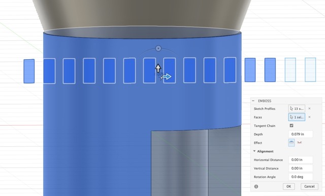
And I used the "emboss" function to put studs the same size as my TPU mesh on both components, to make it easier for the mesh to grip the components.
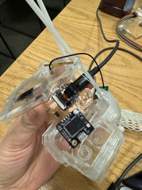
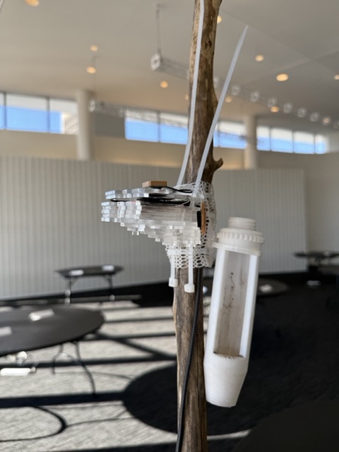
Here is the final assembly of the top component:
Elegant, adjustable, and secure, if I do say so!
December 15
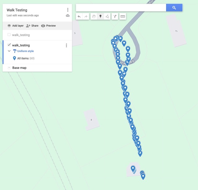
The last things to do before demo day were take some walks down the driveway to get some sample data for my Walk Visualization. I took the stick outside and captured some images and depth readings (even though the ground was frozen so no soil samples were possible).
Here's a sample ESP photo:
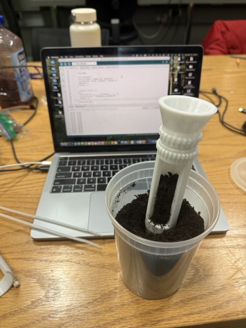
And some evidence of testing the soil sampler indoors:
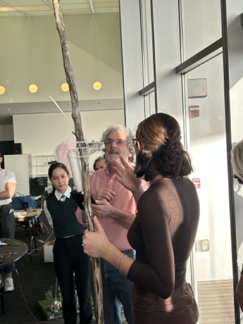
I then put together my demo, my documentation, and loaded the stick into the car (it barely fit) for demo day.
Choosing a 2+m tall stick is optional...
And time to present the final product, with data!
//// Checklist of Skills: ////
2D and 3D design (2D laser cutting sketches for PCB holder and PCB design; 3D cross-section for 3D printed sampling end)
multiple additive and subtractive fabrication processes (laser cutting, 3D printing, PCB milling, zip-tie weaving, a lot of hot glue)
electronics design and production (custom PCB with soil and location sensing capabilities)
embedded microcontroller design, interfacing, and programming (ESP32 S3 Sense with camera module, plus stick-integration sketch for recording data from all sensors via microcontroller)
system integration and packaging (PCB holder with secured electronics, TPU mesh system for flexible stick attachment)
What are the implications? (mobile soil sensing without environmental disruption!!)
/// Initial Project Objectives ///
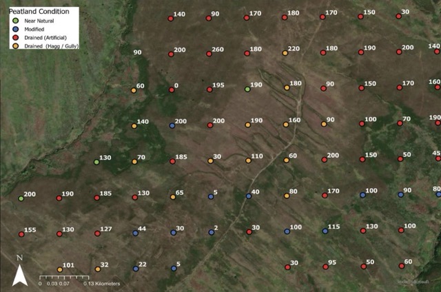
My aspiration is to create an artistic but functional soil-sensing device that connects to my research on peatlands in Northern Ireland. As a design object, I will include this piece for display in an exhibition on this research later this year.
The research associated with this exhibition, which is also the subject of my MCP / MS EECS thesis and my MAD Fellowship project, deals with peatland restoration in Northern Ireland. Peatlands are the most efficient terrestrial carbon stores on Earth, and while Northern Ireland has a high coverage of them (about 18% total peat soil coverage), the vast majority (estimated at 18%) are degraded. The newly released Northern Ireland Peatland Strategy to 2040 follows recent measures in England, Wales, and Scotland to coordinate peatland restoraiton as part of a broader investment in Natural Capital across the UK.
My project follows the technical, social, and historical dimensions of this restoration effort. Peatlands have strong cultural significance, especially in Ireland. This is manifested in the poetry of Seamus Heaney, the ancient bodies preserved in bogs for centuries, and the archeological treasures the bogs have preserved.
Across time, boglands have held a variety of social meanings; they have been interpreted as mystic grounds for worship and sacrifice, as wastelands in need of improvement, as fuel sources to be drained, cut, and dried for bricks to burn, and most recently as powerful carbon sinks in need of large-scale rehabilitation.
In the present, the interpretation of these landscapes integrates all of the forementioned historical vestiges as well as new layers of remote sensing, government-subsidized restoration, and speculative new modes of land valuation in a "Stack" that extends from the soil to the state to the satellite. As peatlands become re-saturated as a part of broader decarbonization efforts, these cultural and technical touchpoints are opportunities for expansive thinking about the way that people feel about their land, and the structures of property and governance that formalize that affinity.
/// Project Background and Ideation ///
Peatland monitoring is essential to peatland restoration in the UK, and many resources have been produced in order to make this practice accessible to landowners and citizen scientists. The Northern Ireland Peatland Collaborative Network published the following Minimum Monitoring Guidelines based on the IUCN UK Peatland Programme's Eyes on the Bog Manual for baseline and continuous bog monitoring.
Both sources emphasize that monitoring of the water table height, peat quality and saturation, and other soil qualities should be conducted regularly and thoroughly, however the Eyes on the Bog Manual observes that restored and natural peatlands are highly sensitive to trampling-- this means that damage to fragile vegetation can be caused even by the annual visiting of the same site.
In response to the dual needs for both continuous monitoring and minimal trampling, I am proposing a modular, convertible monitoring kit that is not anchored to a single site but rather mobile across an entire monitoring area.
It takes inspiration from various monitoring techniques, for example:
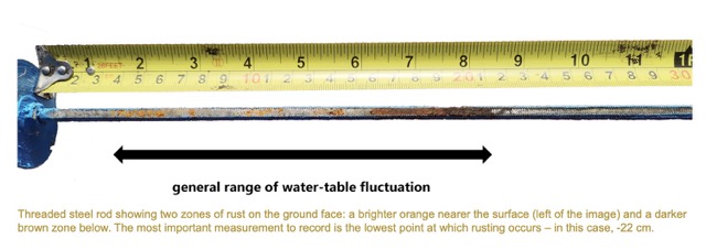
Rust Rods
as shown above are anchored in peat for months at a time, developing rust at the level of the water table. My device will offer a way to sense changes in moisture at a single moment in time and at different locations.
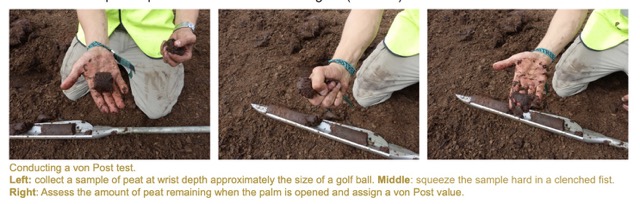
Additionally, the
Von Post
test performed above involves simply squeezing peat samples in the hand to determine how much soil mass disintegrates. The spade used to collect such samples will be an inspiration for this project.
Device Design and Planning
In Week 1 I developed a conceptual diagram for the device I would like to build, describing its sensing, sampling, and location tracking capabilities. The aspiration behind this device is to be able to take a walk through a bog, sensing soil qualities as you go, and to come home with a map of your walk and the data you collected:
The component on the bottom of the stick is based on the Russian Peat Corer by Aquatic Research, which can take soil samples using a rotating chamber. The Peat Sampler Set by Royal Eijkelkamp is a very similar device, and the Manual for it describes how it works.
Based on my initial designs and the insight from Anthony that a LiDAR or Ultrasound depth sensor would be a good choice (and would therefore need to be located at the top of the stick, while the sensors and sampling equipment are at the bottom), I believe the device will work best as two components: an upper device (with most of the electronics and the depth sensor) and a lower device (with the sampling spade and moisture sensing).
Upper Device: Moisture Sensing
I think sensing the moisture of the soil electronically is an innovation in peatland sensing, as this usually is done using very low-tech methods for water table tracking over time. My best lead for a sensor for this is the Adafruit STEMMA Soil Sensor, which uses capacitive sensing (like a finger pressing a button) to capture a measure from 200 (dry) to 2000 (wet) as well as a built-in ambient temperature reading from the SAMD10 microcontroller. This seems like a great option for integrating with the project, as it can connect to any microcontroller using an I2C interface.
Initially, I imagined this component as part of the lower device, but upon some consideration I believe it should be integrated with a holster for the sampling end that attaches at the top of the stick. This puts soil depth and moisture sensing on the same PCB, which is also useful.
Upper Device: Ultrasound
This Ultrasonic Sonar Distance Sensor from Adafruit is amazing, and it can sense distance within a few centimeters. My idea is to use this sensor or a similar one to sense the distance from the top of the stick (an arbitrary distance established at boot-up) and the ground. As this distance diminishes, the depth of the corer and sensors (lower device) is calculable as difference between that initial distance and the present one, minus the distance of the sensors and corer from the end of the stick.
Upper Device: Electronics Integration
In class I learned to use the XIAO RP2040 microcontroller with Arduino code. This would be a good option for my project, although I need more pins. Mid-semester, I am planning to use a Raspberry Pi Pico W, which has the same RP2040 processor but additionally offers more pins and Wi-Fi connection capabilities.
Lower Device: GPS
While I have been warned that GPS sensors are not accurate within very precise distances, especially indoors, the GPS available will be able to track a walk of 1-10km outdoors. I initially imagined the GPS at the top of the stick, as part of the upper device. However, in order to capture measurements each time the stick touches the ground, it needs to be electronically linked to a button at the bottom of the stick; thus it should be part of the lower device.
Lower Device: Peat Sampling
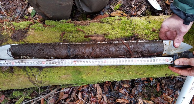
Below is a photograph of a sample that the US Geological Survey took from the Great Dismal Swamp in 2017, showing the kind of sample a peat borer withdraws:
The cores taken from these devices tend to be about 50cm long, which I expect to be too long for a 3D printed part to hold up against. My thinking is to make a this component about 25cm long, so that the force exerted on the stick and the 3D printed tool end is not excessive. In order to compromise operation between the GPS button and the sampling functionality, I imagine that the sampling end will be able to screw on and off of the bottom of the stick as needed, and when not in use it can be attached to a holster on the upper device.
The Stick (and adhesion)
My hope is that this two-part device will be able to attach to any stick. To test this, I am amassing a stick library in my garage:
In order to attach to sticks of varying diameters, both parts will need to use some strategy of attaching securely while remaining removable. I do not want to have to modify the stick I think some combination of a rigid adjustable frame with a flexible interior. Maybe this looks like a belt with variable width, that is also stretchy or grippy.
I think this may be possible to 3D print with TPU according to the Prusa Website. This Multipurpose TPU Strap by Hans Hiorth seems like a good reference. I could imagine having two of these attached to the housing for both the upper and lower devices respectively. I would probably redesign it to be wider (create more surface area touching the stick) and have a buckle with multiple prongs.
Components and Skills
Below some notes connecting the components of the device to specific skill categories (both taught and not-taught in this class):
Mechanical Design
to develop an adjustable appendage that can capture soil samples.
3D Printing
to create the sample withdrawal component and housing for electronics.
Electronics
to link microcontroller to GPS, buttons, and sensor(s).
Input Devices
for capacitance (moisture), images, distance or depth (from top of stick to ground), pressure (tap), and GPS location.
Embedded Programming
to program behavior of sensors.
Web Interface Programming
to display instructions access and display sensed data and sample locations on map.
 Production is explained in much more detail in the next section. Thank you for a great semester!
 And following are the tasks that remain to be done:
 The other progress I made this week was towards developing my soil sampling device. I started out by designing and 3D printing two simple prototypes: one with absolute minimum features and a flat profile, and one with a round profile and a small wing to try to capture the soil sample better.
 After designing these in Fusion, I sliced them and 3D Printed them in white PLA. The print took about 4.5 hours.
 Then, I took them on a walk in the woods. I went down the trail near my house and stopped at a marshy area of the woodland, where the ground would be soft and boggy.
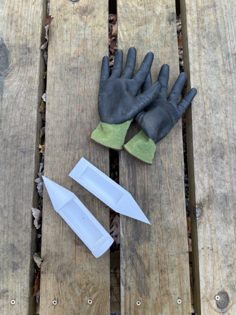 I tested each of the corers in a different area of the soil, and evaluated the sample it took. The samples are meant to be withdrawn by pushing the sharp end of the corer into the dirt, and then spinning it around to capture some soil in the reservoir area of the corer.
 Neither of them performed as I wanted-- what I'm shooting for is more like the USGS reference below:
 In fairness, their soil is much more moist than mine was, so it made a cleaner sample. I think, while I hoped that the curved sampler would perform better, it ended up putting to big ofa hole in the soil as it entered the ground, making it impossible to reach the sample around it. In the next iterations, I will refine the flat version to be longer and have sharper edges that can capture the soil better. I was pleased to note that the PLA was sharp and strong, so I think it will be a sufficiently robust material for this task.
 I hope to test this soon as the ground is rapidly freezing!
 I also found another reference with more cuffs that seems like it would be helpful for attaching well to a stick. I imagine that the bottom of this could have holes that correspond to bumps or "buttons" on the rigid part of the lower device.
 I want to experience with making a "knitted" looking PETG cuff for the grippy part, and I found some plumbing parts at home (thanks contractors) to test with.
 Even with the electronics consolidated at the top of the stick, I still need an element at the bottom of the stick to hold the sampling end. This mesh will help me attach both.
 Above is the PCB visualization for the final board.
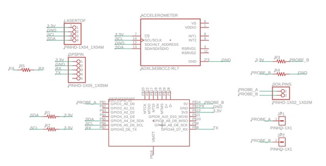 And the corresponding schematic.
 Next, I attached all the components. This was delicate because it involved using solder paste to attach the accelerometer and a clamp to get the wires for the capacitive sensor right.
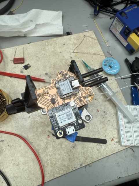 With this I was ready to start testing.
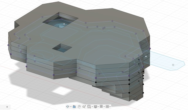 I made sure to include holes and voids where the electronic components would go (based on a fusion mesh of my actual PCB), so that the whole assembly would pass the "shake test":
 Once I had cut all the components from acrylic, I used vertical zip ties to register all the parts together and super glued them. To hold the electronics in place, I used some strategically placed hook-and-loop patches so that things would stay put when I was testing but still come apart easily in case of an issue.
 I removed and wove the vertical zip ties through the mesh to hold the electronics onto the stick; it then attached using horizontal zip ties looping through the same mesh. All the components are visible in this flat-lay:
 For the soil corer final version, I was inspired by this example and redesigned a smaller one for my purposes. I used the analysis layers in Fusion to visualize a threaded connection between the sampling end (to be held at the top of the stick when not in use) and the boot:
 And I used the "emboss" function to put studs the same size as my TPU mesh on both components, to make it easier for the mesh to grip the components.
 Here is the final assembly of the top component:
 Elegant, adjustable, and secure, if I do say so!
 And some evidence of testing the soil sampler indoors:
 I then put together my demo, my documentation, and loaded the stick into the car (it barely fit) for demo day.
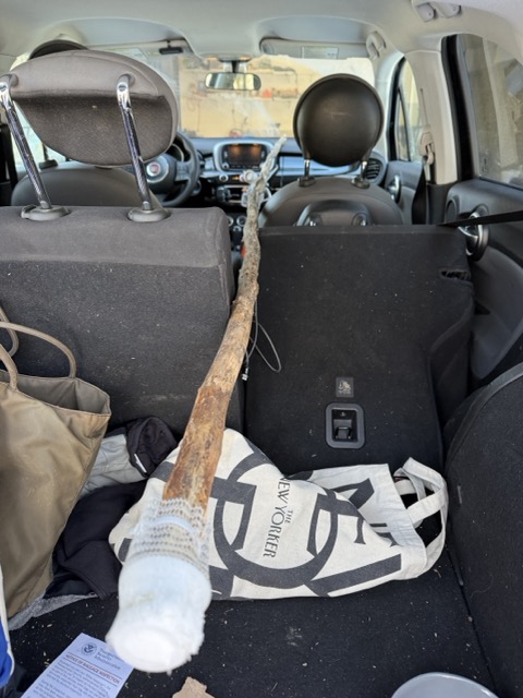 Choosing a 2+m tall stick is optional...
 And time to present the final product, with data!
 Both sources emphasize that monitoring of the water table height, peat quality and saturation, and other soil qualities should be conducted regularly and thoroughly, however the Eyes on the Bog Manual observes that restored and natural peatlands are highly sensitive to trampling-- this means that damage to fragile vegetation can be caused even by the annual visiting of the same site.
 Additionally, the
 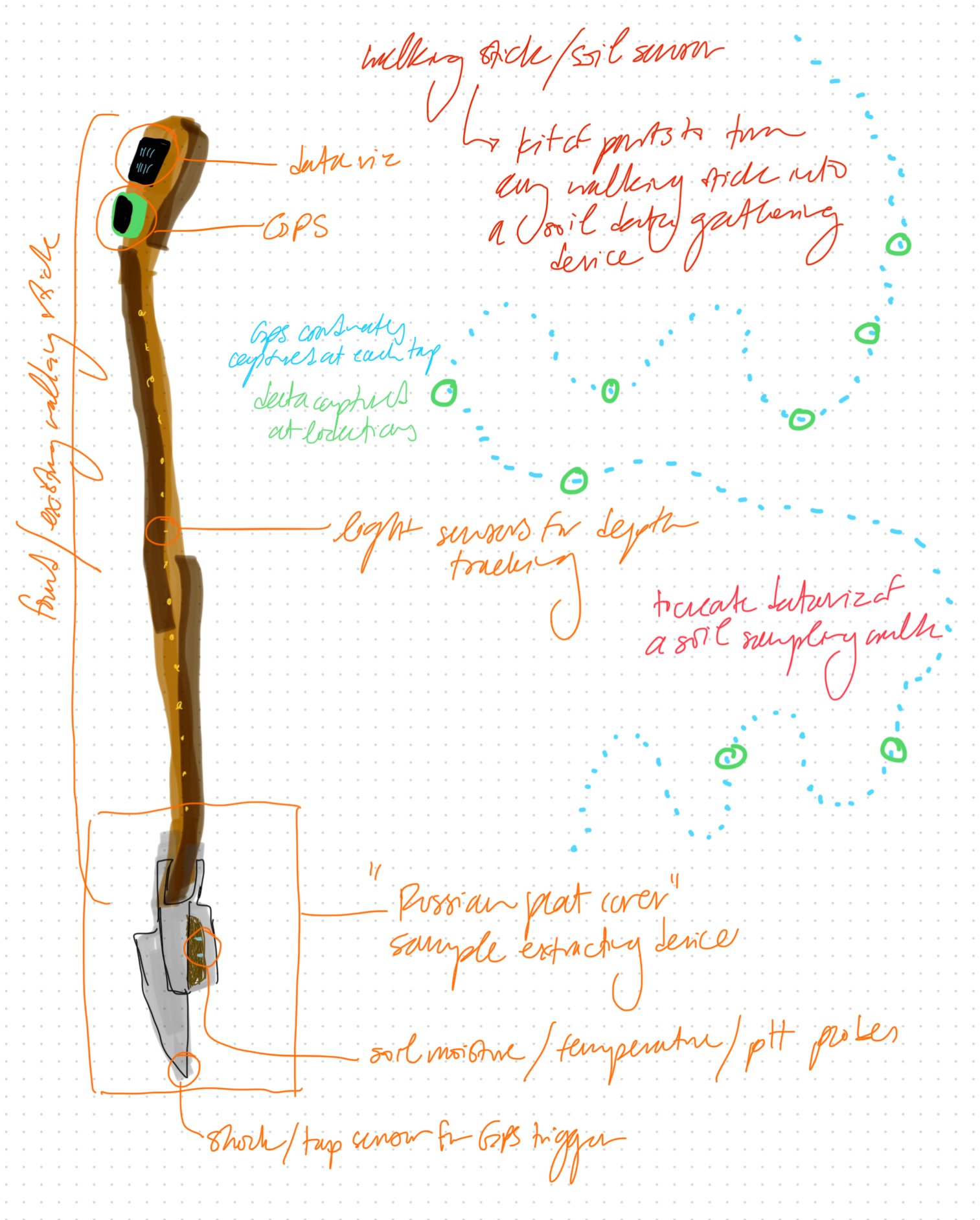 The component on the bottom of the stick is based on the Russian Peat Corer by Aquatic Research, which can take soil samples using a rotating chamber. The Peat Sampler Set by Royal Eijkelkamp is a very similar device, and the Manual for it describes how it works.
 Based on my initial designs and the insight from Anthony that a LiDAR or Ultrasound depth sensor would be a good choice (and would therefore need to be located at the top of the stick, while the sensors and sampling equipment are at the bottom), I believe the device will work best as two components: an upper device (with most of the electronics and the depth sensor) and a lower device (with the sampling spade and moisture sensing).
  The cores taken from these devices tend to be about 50cm long, which I expect to be too long for a 3D printed part to hold up against. My thinking is to make a this component about 25cm long, so that the force exerted on the stick and the 3D printed tool end is not excessive. In order to compromise operation between the GPS button and the sampling functionality, I imagine that the sampling end will be able to screw on and off of the bottom of the stick as needed, and when not in use it can be attached to a holster on the upper device.
 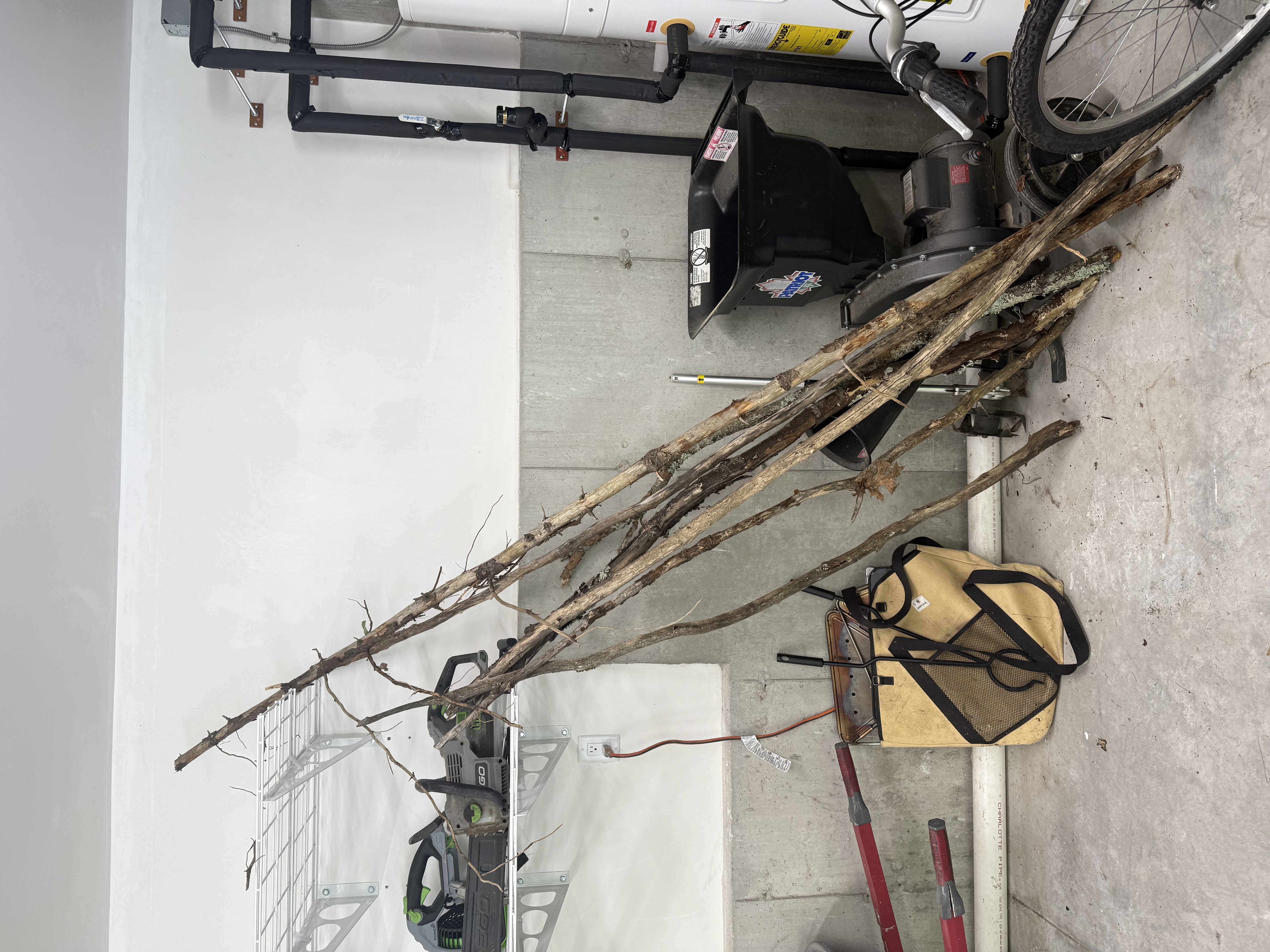 In order to attach to sticks of varying diameters, both parts will need to use some strategy of attaching securely while remaining removable. I do not want to have to modify the stick I think some combination of a rigid adjustable frame with a flexible interior. Maybe this looks like a belt with variable width, that is also stretchy or grippy.