Introduction
My idea is to build an electronic stargazing/Binocular chair that can hold a person sitting on it, with the motors to control the two rotational axes and realize the GOTO system (which means the computer can use the celestial body coordination database to point the telescope/binocular automatically)
1. A historical survey of StarChair
The Sky Rover StarChair was a short-lived commercial product marketed as a motorized reclining “stargazing chair.” Released in the early 2000s under the Sky Rover brand, it was designed to let users comfortably track the night sky by tilting and rotating while lying in a zero-gravity style seat.
Although the idea attracted attention in astronomy and hobbyist communities, the chair was discontinued after a relatively brief market presence. Reports suggest that high manufacturing costs, limited demand, and mechanical complexity contributed to its withdrawal. Today, the StarChair survives mostly in references on enthusiast forums and product archives, with no active production or direct successor models.
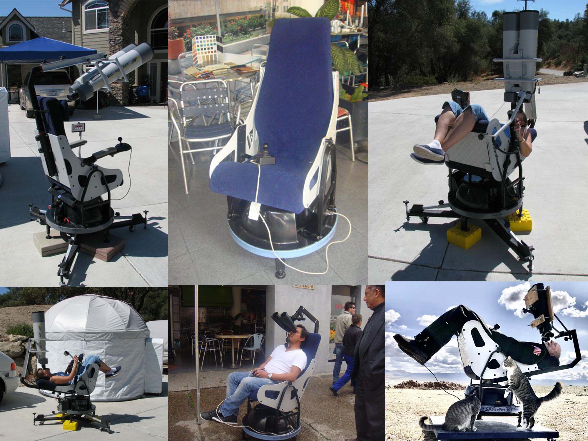
In 2004, when it came out, it was labeled as $ 3950, made in Australia; now it even needs around $ 7000 to buy it since it stopped manufacturing and selling. The structure of it is not so complex, and computer technology has developed a lot over the past 20 years. It shouldn’t be very hard to make a DIY one nowadays
2. Lots of amateur Astronomers tried this idea with the manual version:
1)Custom Binocular Chair with bike wheels and zero-gravity chairs
Binocular chair stargazing, with comfort and stability
.jpeg)
2)Another similar version with a zero-gravity chair and an alpenstock to rotate:
DIY Astro Binocular Chair - YouTube
But I doubt the zero-gravity chair can be very useful for my GOTO system, since the rotation of that for pitch angle might not be linear. But the rotatable base plate design is useful for reference.
3)Gary’s Motorized Big Bino Chair
Also, with a zero-gravity chair but it can rotate the base plate with an electric drill?!
By the way, the design with some elastic rope to balance the angle of pitch can be a good idea?
.png)
4)A book systemically introduced about the homemade Binocular chair:
link.springer.com/content/pdf/10.1007/978-3-319-46789-4.pdf
.png)
5)A Post with discussion about the body weight problem, portable design and even the vibration from heart beating:
Motorised Binochair design for 100mm binoculars - Discussions - Binoculars - Stargazers Lounge
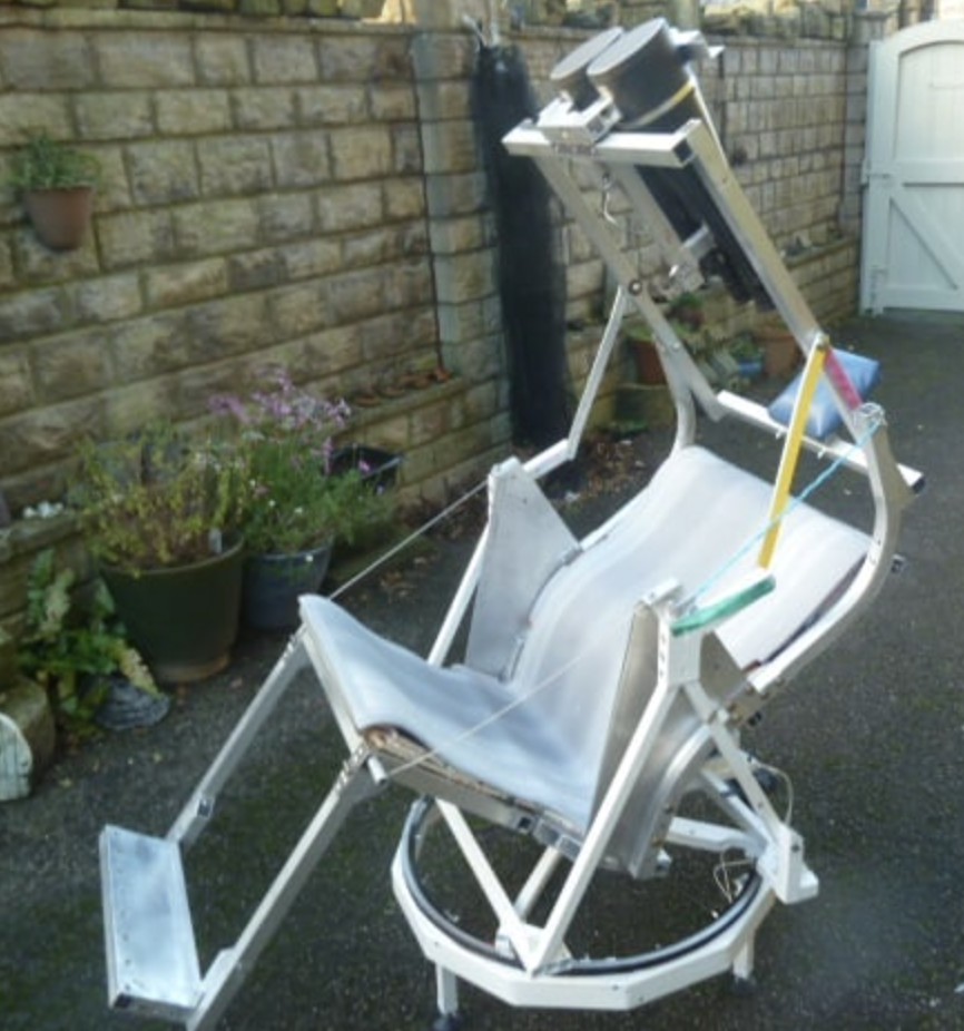
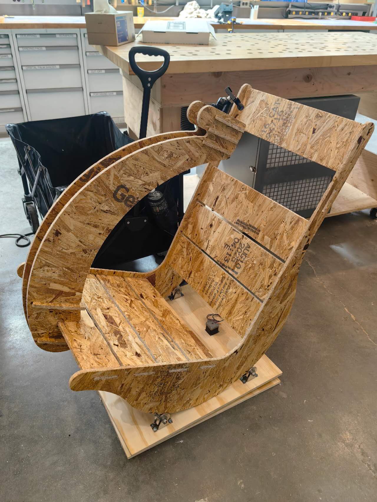
3. My first prototype of a manually rotatable chair
During week 7: “How to make something big”, I decided to make a prototype of a stargazing chair for my final project. More detailed processing documentation can be found in week 7: Huanyu HTMAA 2025 week 7
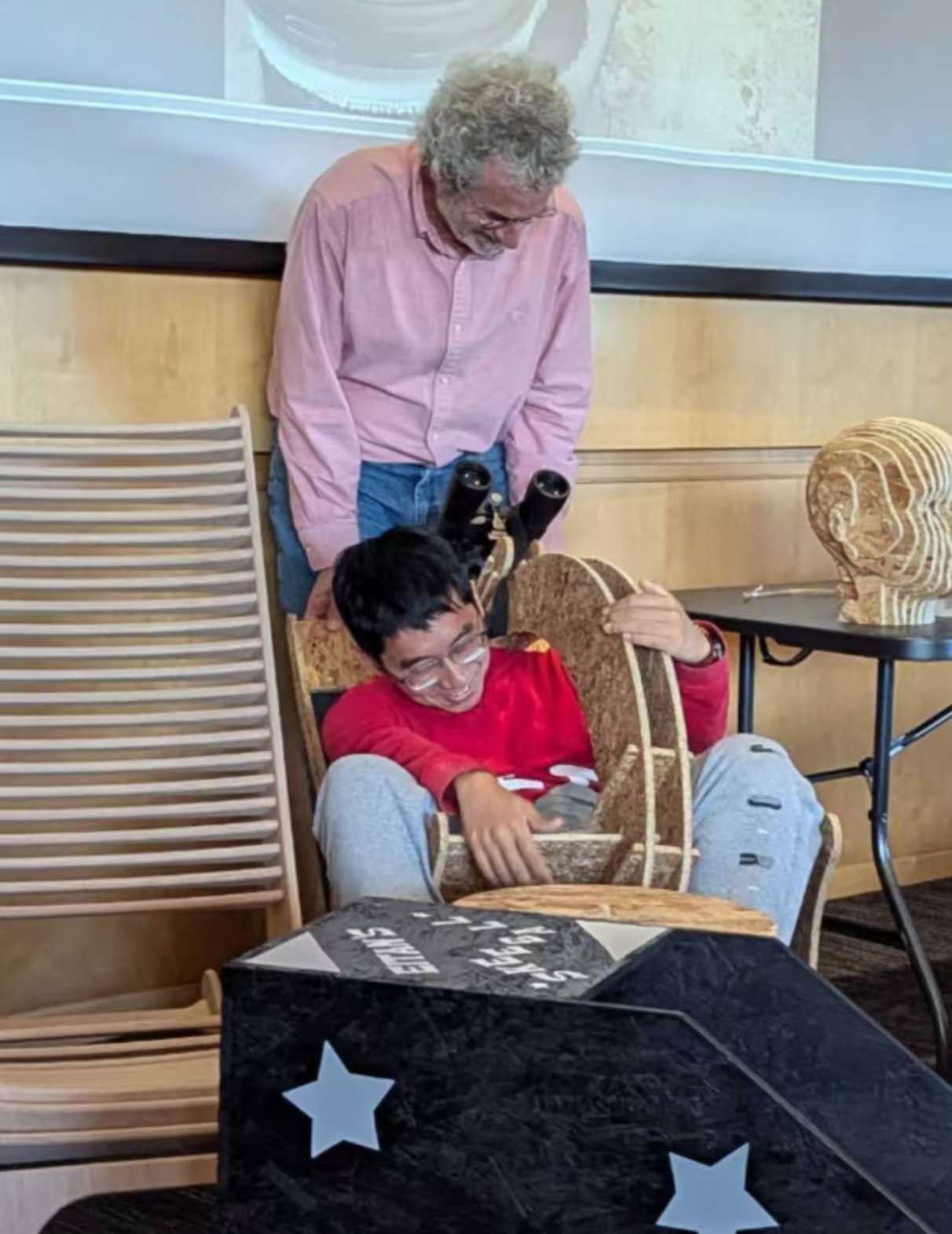
Based on the experiment, I found that the pitching axis of this design is very unbalanced, as expected. And the cheap Oriented Strand Board is not strong enough, which will distort and cause the binoculars to change position. Here is a photo taken by Anthony showing my in-class presentation of the prototype that I couldn’t get up by myself because of the chair’s unbalanced structure.
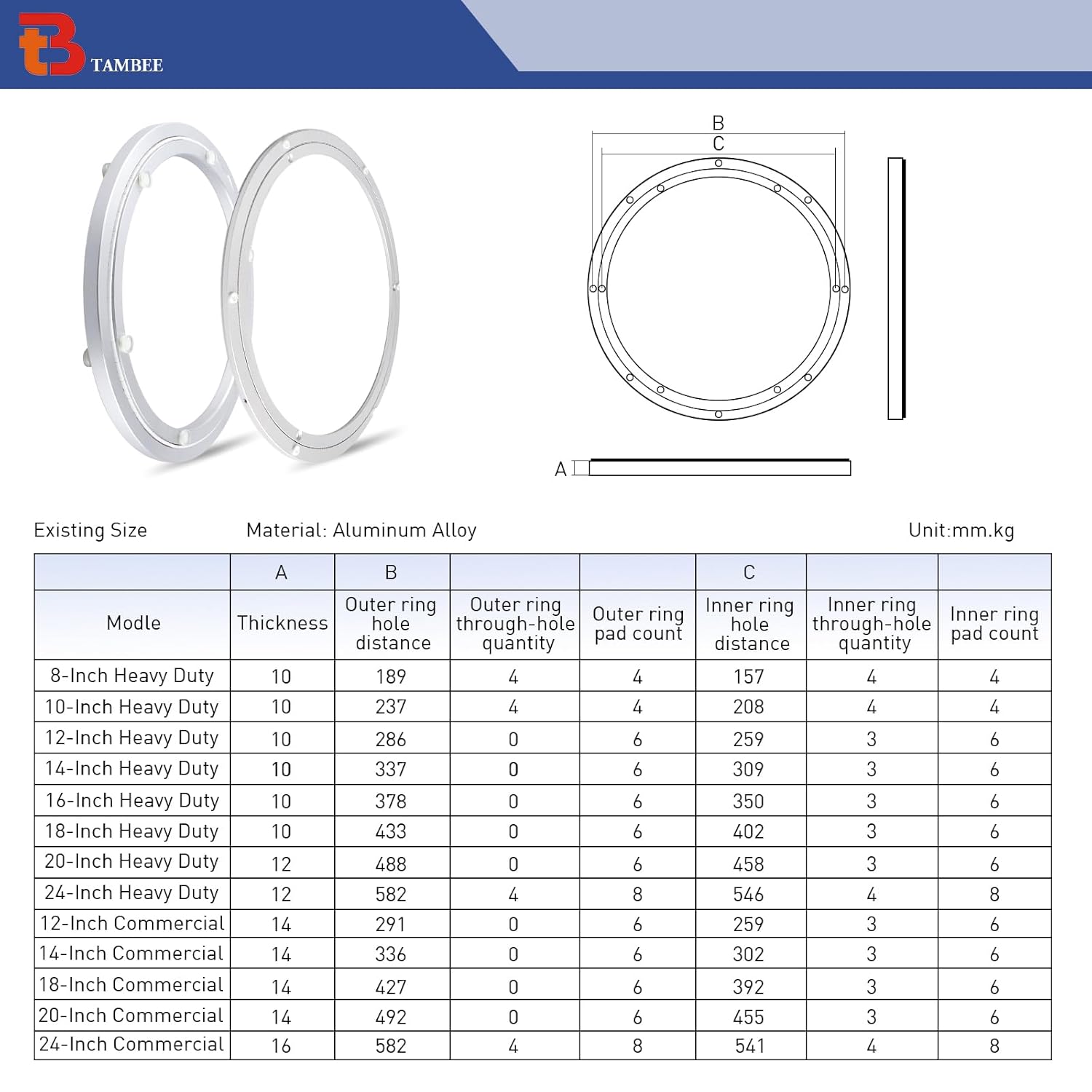
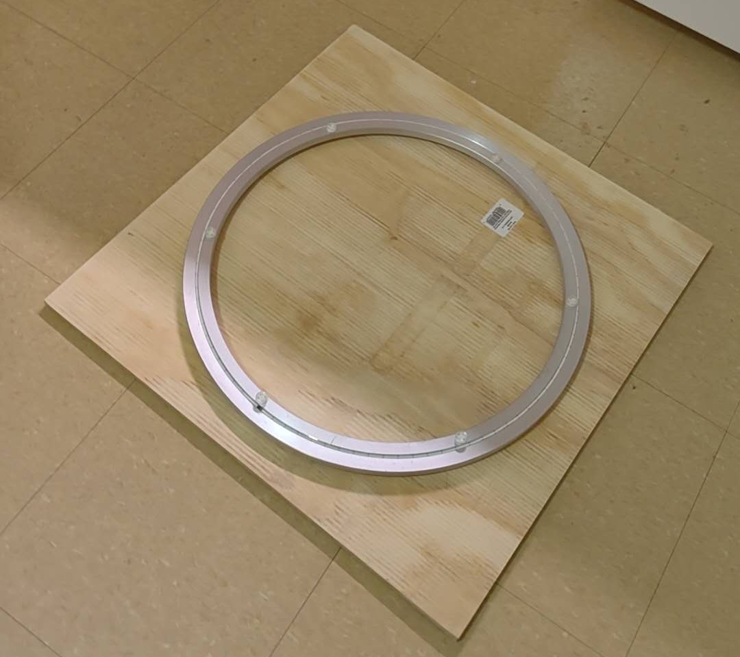
However, I bought a big Lazy Susan 20-inch turntable bearing from Amazon, and it is strong enough to support my horizontal rotation axis: (20-inch commercial one). It was not tested on a prototype because of the delayed shipment and the missing round base after the class, but it would work well, and my future design will focus on using it.
4. The astronomical AI chatbot on the chair
Apart from the complex mechanical design and motor controlling problem, I also have an idea to make the smart chair more interesting: design a device on the chair that is connected to AI through the internet to chat with users about astronomical knowledge when they are doing stargazing. My own observing experience told me that it will become boring easily if you look at stars for the whole night, especially for the general public, and they always ask strange questions like the distance of some stars, which can be hardly remembered, but can be easily and accurately answered by a modern LLM model like ChatGPT. The scientific reliability of ChatGPT nowadays is good enough for most public science scenarios.
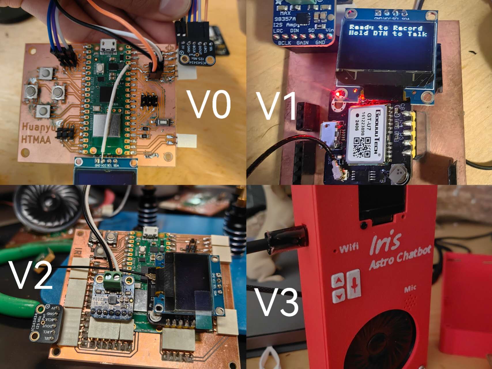
To achieve that result, there are lots of existing examples that I can learn from (example: ElatoAI - Realtime Speech AI Agents for ESP32 on Arduino). As a result, during weeks 9&10&12, I will focus on the microphone, the speaker, and the networking system building for this sub-system of my smart stargazing chair. This chatbot is named as “IRIS”.
Relevant progress:
Week 9: input devices & microphone (Iris V0 breakout test) Huanyu HTMAA 2025 week8
Week 10: output devices & speaker (Iris V1) Huanyu HTMAA 2025 week9
Week 12: Networking (Iris V1 and echo test) Huanyu HTMAA 2025 week 12
Following: Redesigned broad schedule, AI test, 3d printed boxes and buttons: (Iris V2 and V3)
5. The material and design of the new rotatable base plate:
To get stronger material for my new chair base plate, I went to The Home Depot to buy the new wood plates. I finally decided on the 2-foot*2-foot square 5-layer plywood board (~$10/each) since it’s cheap and easy to bring back (I don’t have a car). And this size is good for the base plate, so I don’t even need to machine the outline. It can rotate smoothly when it’s between two boards:
The idea of adding the stepper motor to drive it: dig big holes in the center of two base plates, and set the smaller gear ring in the middle, also set the stepper motor at the center to be hidden in the big rotatable bearing. The biggest issue is how to get the gear ring. Too big one should be expensive and heavy, and I might need to consider using a waterjet machine to cut the gear ring, or use the 3d printer to customize it.
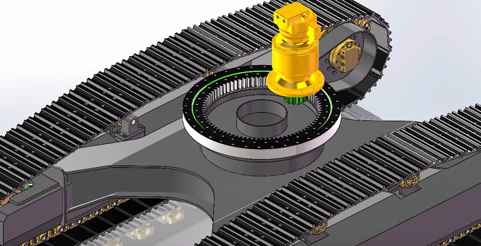
This kind of inner gearing rotary platform is applied uniformly in the design of an excavator, as shown in the following figure:
For the pitching axis, because it might not be balanced so I need the big torque output from the motor. A small one without efficient reduction can’t give me enough torque. Jiaming mentioned he has one extra big motor that can fit my requirement, which looks like this: (12 Nm torque), and I still need to figure out how to design the mechanics of the pitching axis and drive it. 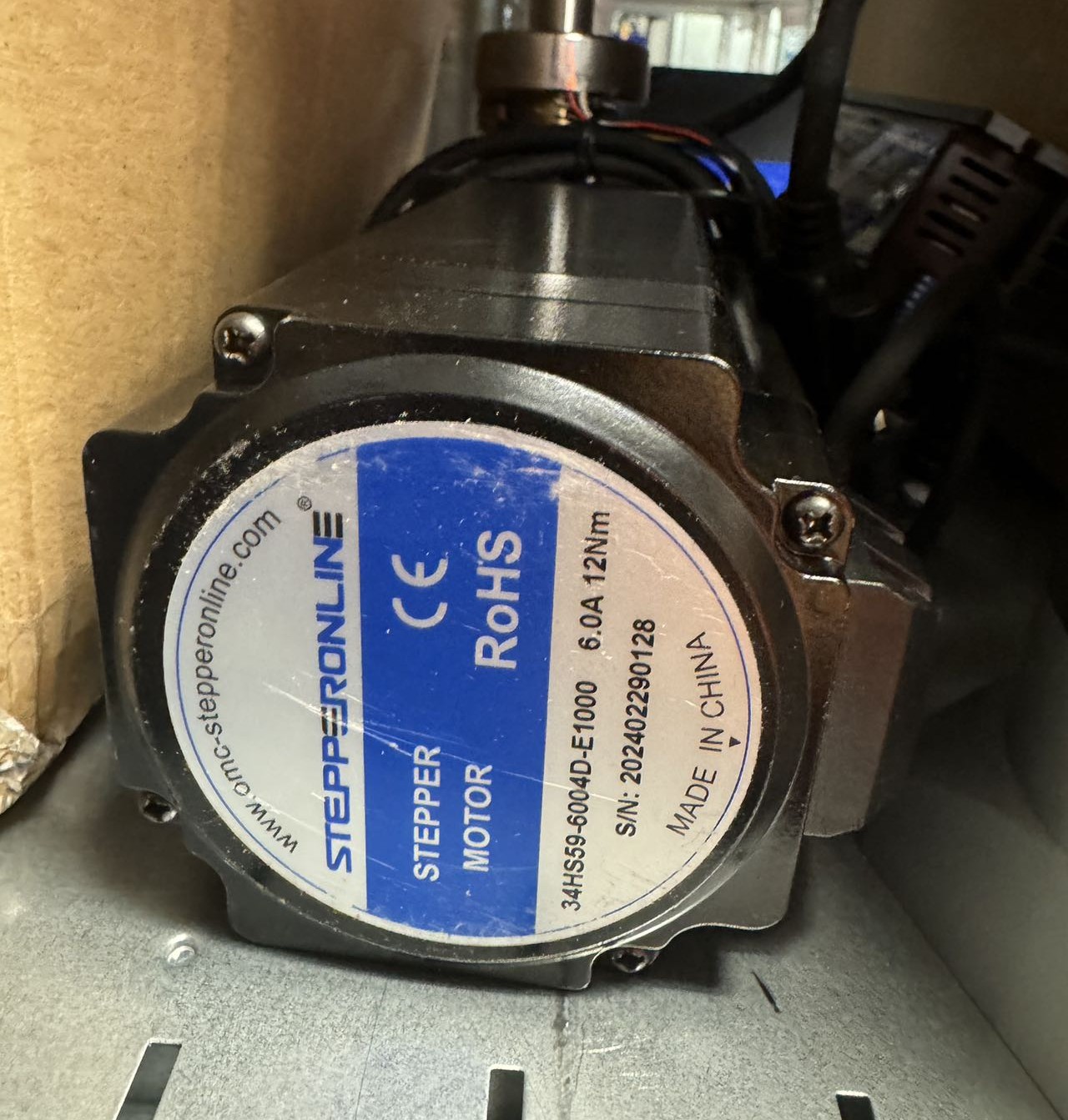
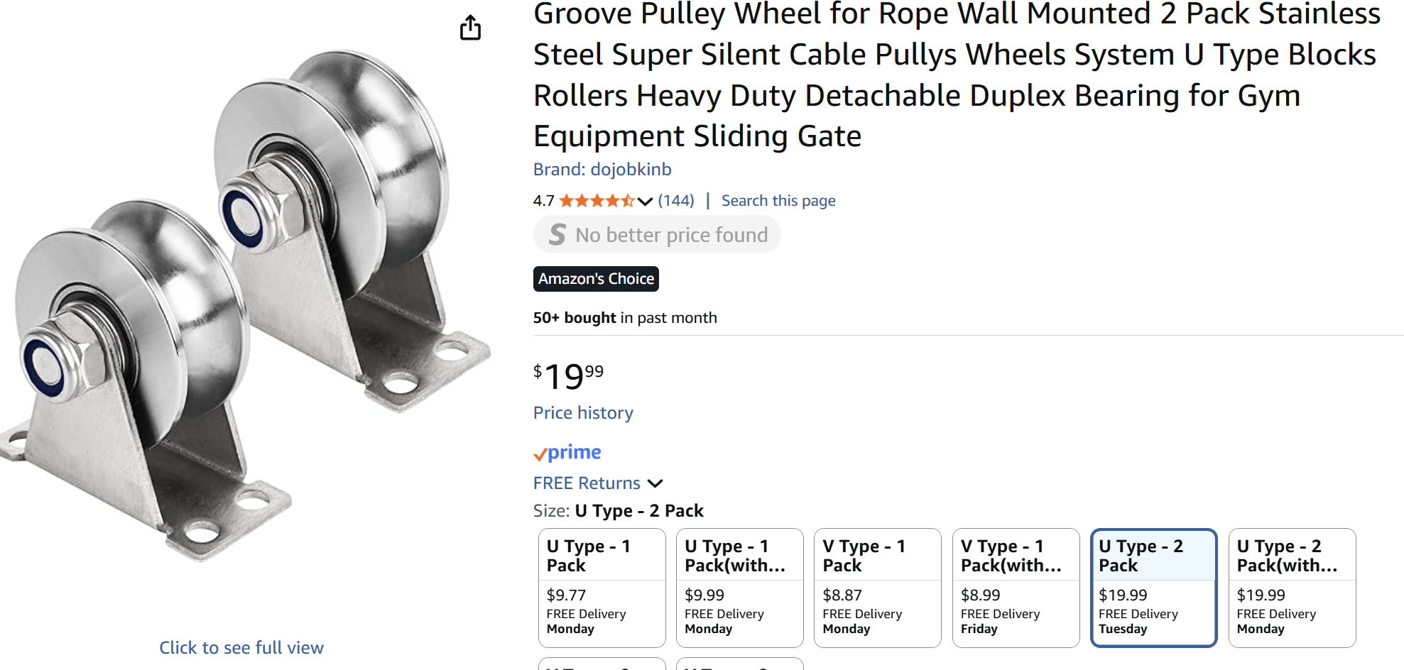
However, I found that the mechanical design of this pitch axis is far more difficult than I thought. Also, driving this kind of high-torque motor is more difficult in both controlling and the power supply. Considering the limited time for the final project, I decided to give up the electronic driving of the pitch axis, with just a manual option for it. But the manual driving still needs a smoother mechanical design, so I bought some Pully wheels: (~$10/each), and then I can use the rocking chair body from my CNC week homework.
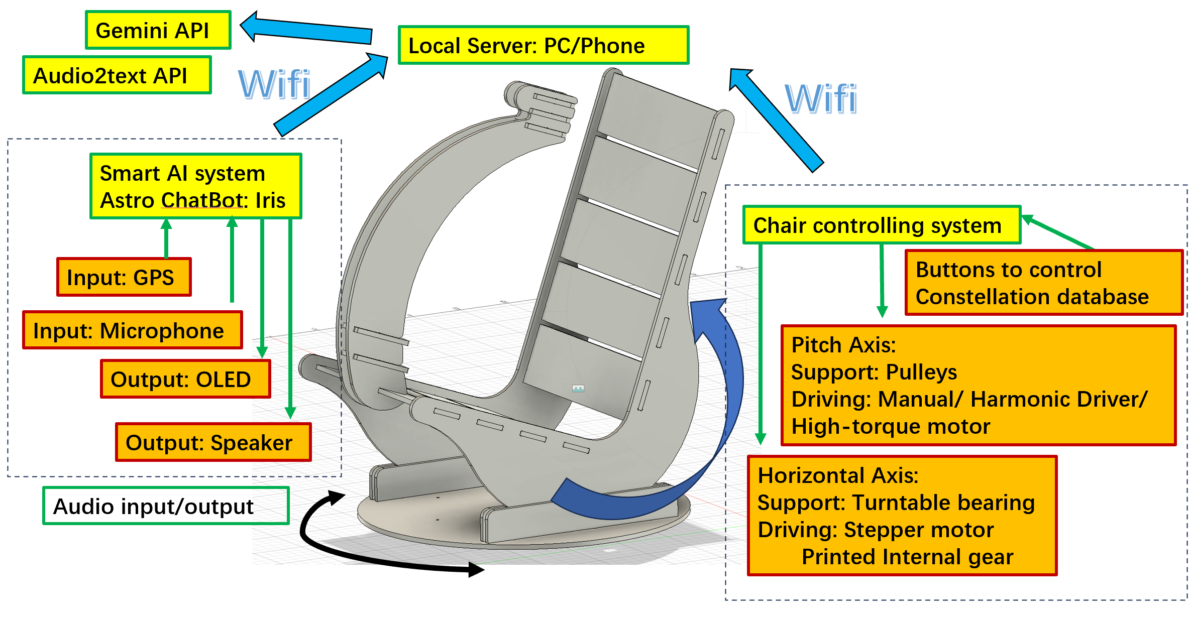
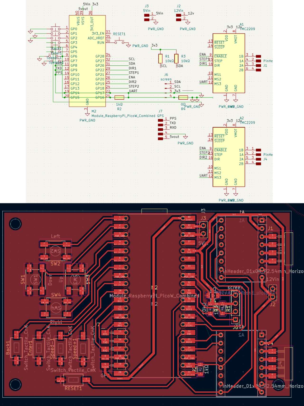
6. The Schematic Diagram for Midterm Review:
In a nutshell, my smart stargazing chair can be separated to two subsystems: the AI Chatbot system (Name: Iris), and the chair controlling system. They both have several input/output devices, and the communication is based on the Wifi (specifically phone hotspot, because the application scenarios would be wild).
7. The development of the smart AI system
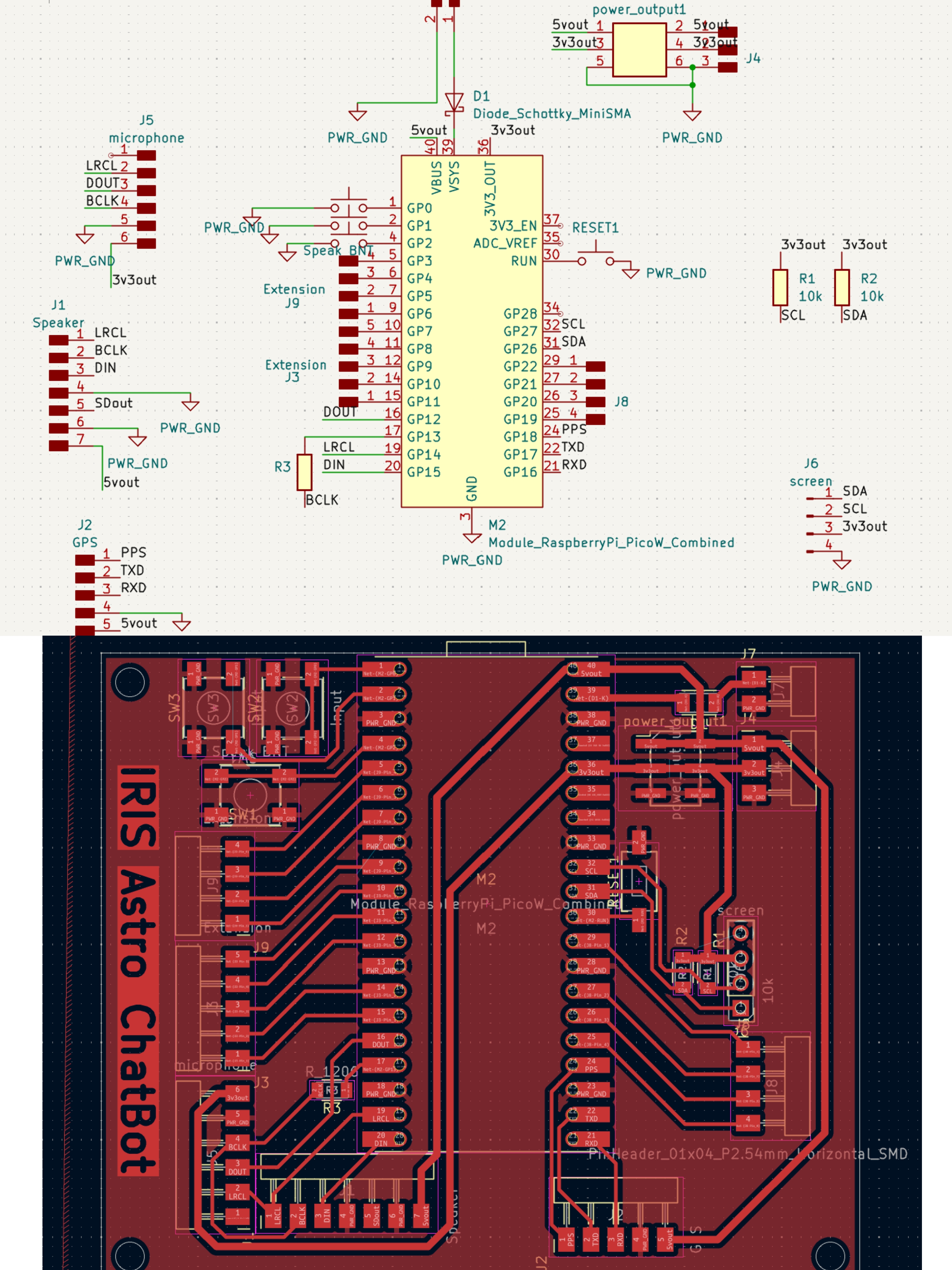
From week 12 for Iris V1 and the echo test (Huanyu HTMAA 2025 week 12), I ensured the logic for the WiFi system, microphone, and speaker was all good. However, when I tried to test the GPS module next, I figured out that the pins TXD and RXD need to be connected to the UART ports, but I randomly connected them to the general GPIOs. As a result, I need to redesign the whole board. Also, I want a beautiful box for this chatbot, so I need to make it more condensed, better to have all modules on a single side of the board (especially for the screen and buttons), which is easier to mount and more friendly for the users. Here comes the V2 and V3 electronic design. There is only a small adjustment from V2 to V3, because for V2, I changed the LRCK and BCLK pins order for I2S, but then I figured out it’s also not acceptable in Micropython. Skip the introduction to V2 for this failed attempt.
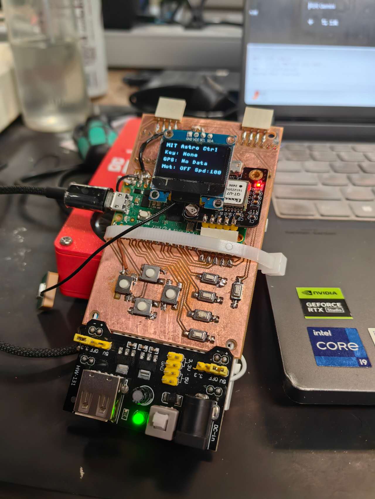
Here is the V3 electronic design. The original files can be found here: IrisV3.zip
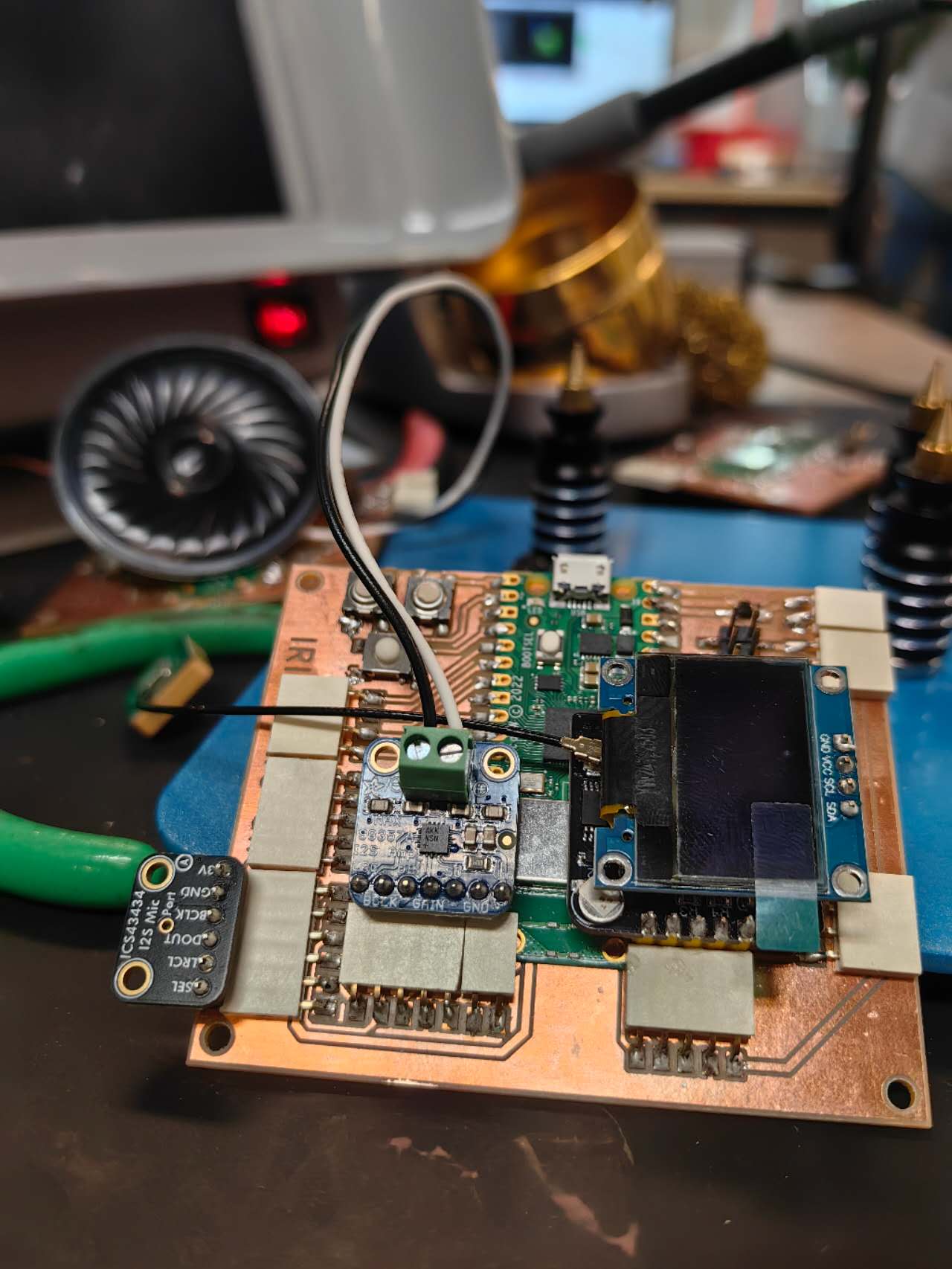
And it looks like this when it’s finally assembled!
To design the 3d printed boxes for that, I measured the size of the board and the positions of parts on that, then used Fusion to CAD it. Fusion CAD file can be downloaded here (https://mymit81.autodesk360.com/shares/public/SH28cd1QT2badd0ea72b0ee5cfdfdf9c3aab)
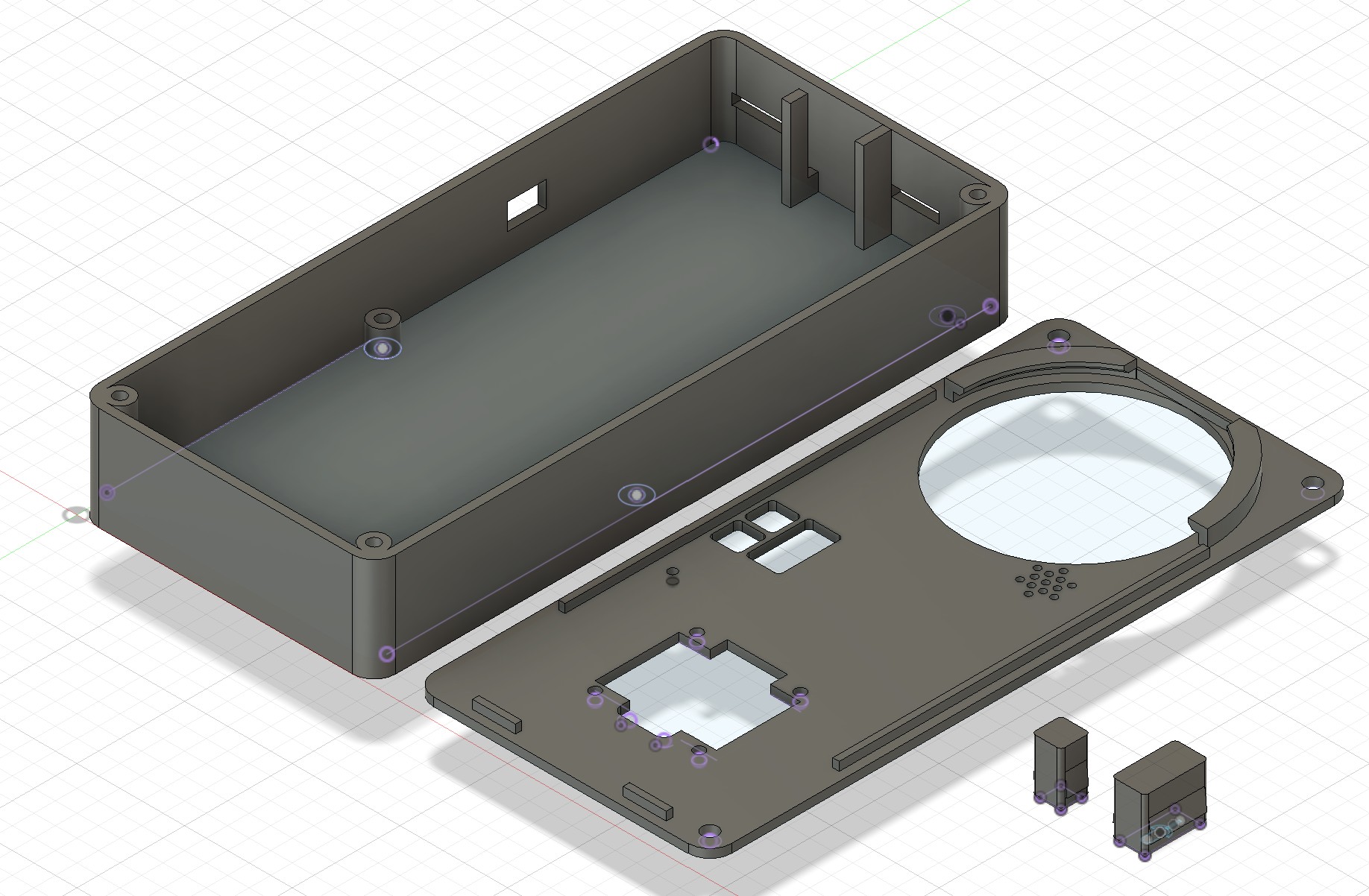
To 3d print the box with some texts on it, I used my dual nozzle printer, Bambu Lab H2D, to do two-color printing without the waste from color changing.
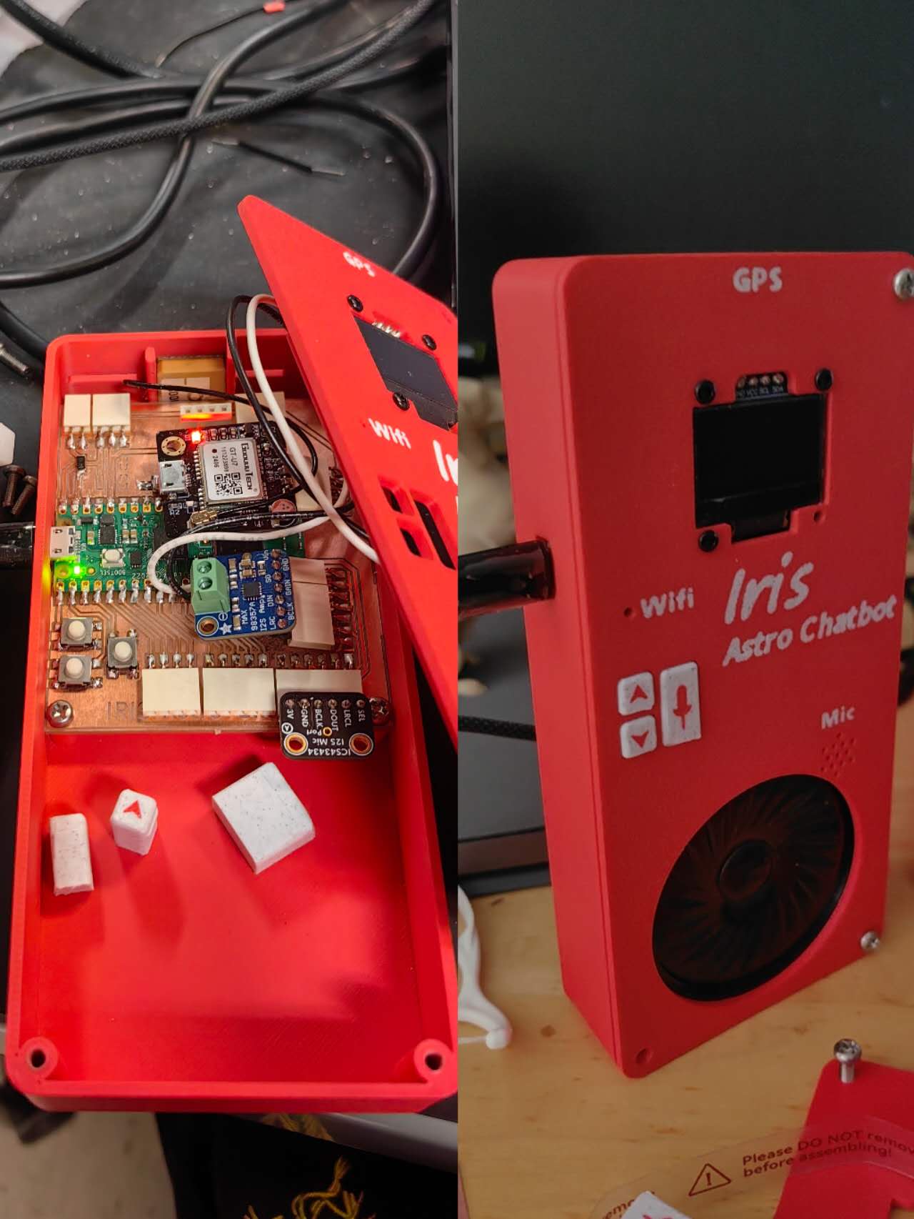
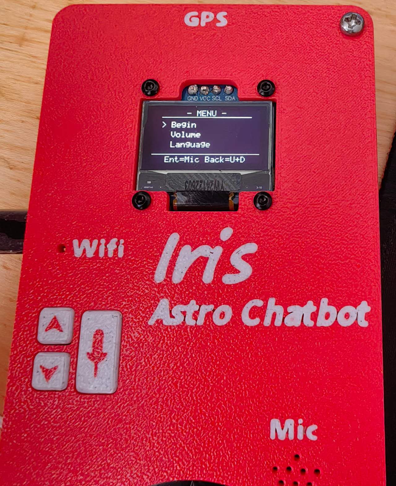
For the codes of this, I designed a menu system which has four options: Begin (for AI chatting), Volume, Language, and GPS. Because I only designed three buttons, the Mic button can be used for “Enter”, but there’s no room for the “Back” function. So I define it as pressing both Up and Down.
The code can be found here:
Gemini_IRIS_PLUS.py (server)
Gemini_IRIS_PLUS_MCU.py (Raspberry Pi Pico W)
The basic logic is that when you press the Mic button under the Begin option, it records the sounds and live-streams them to the server. It will generate a .wav file on the server and then send it directly to the Gemini API since the AI can read the audio. When it gets the text back from AI, it will run a local software called gTTS (Google Text-to-Speech) to synthesize the audio. The server then processes this file into a 16-bit PCM WAV format and streams it back to the microcontroller over UDP for real-time playback.
8. The mechanics of the electronic stargazing chair
First, I CAD the rotatable chair base plate in Fusion: https://a360.co/4nfi076 (original file)
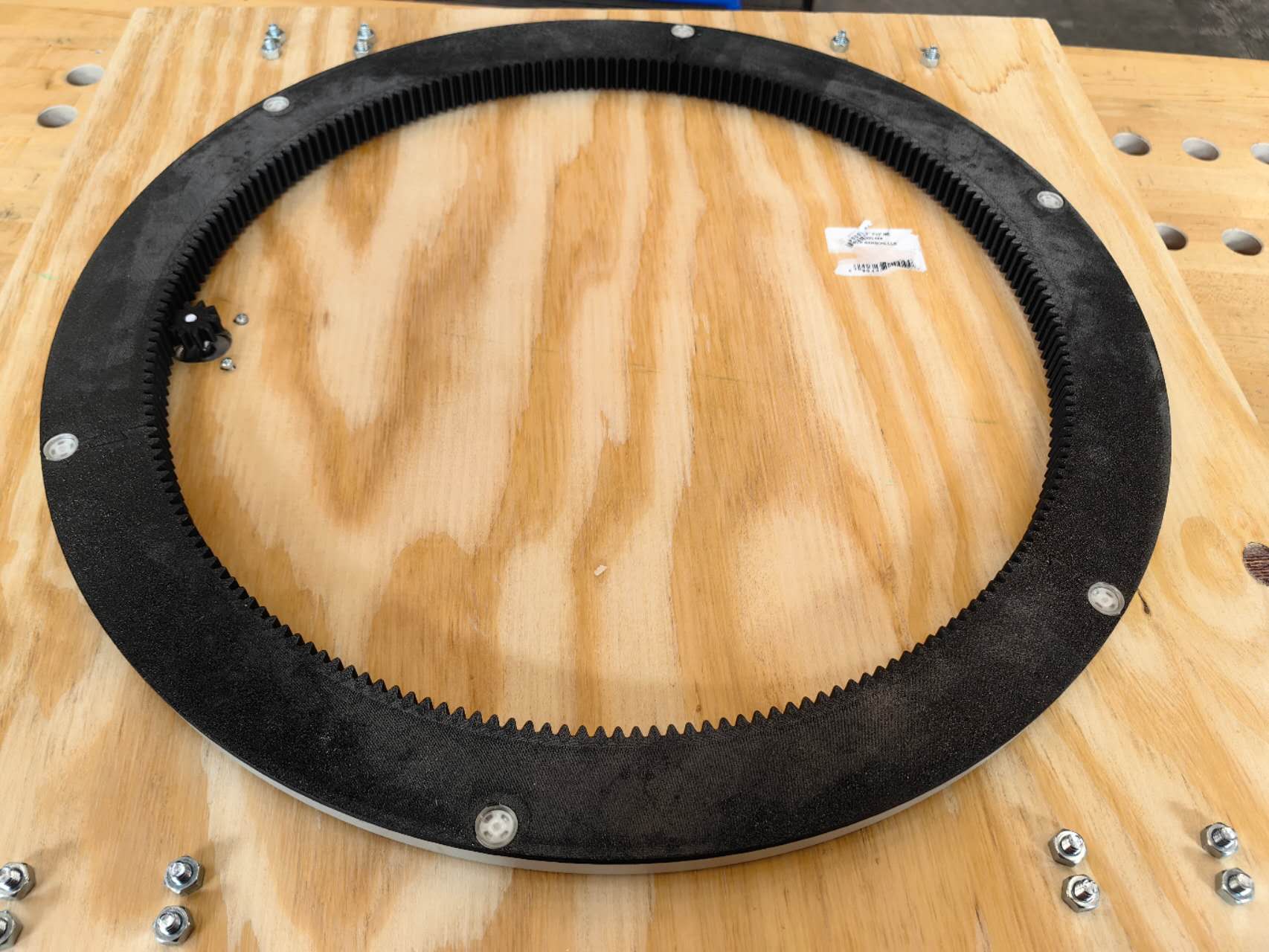
To generate the parametric big inner gear to 3d print, I used the “Spur Gear” plug-in in Fusion (How to create Gears (spur, worm, and helical gears) in Fusion). To print such a big inner gear, I struggled to separate it into 3 pieces like a puzzle, and this can almost fit the biggest printing size of my H2D.
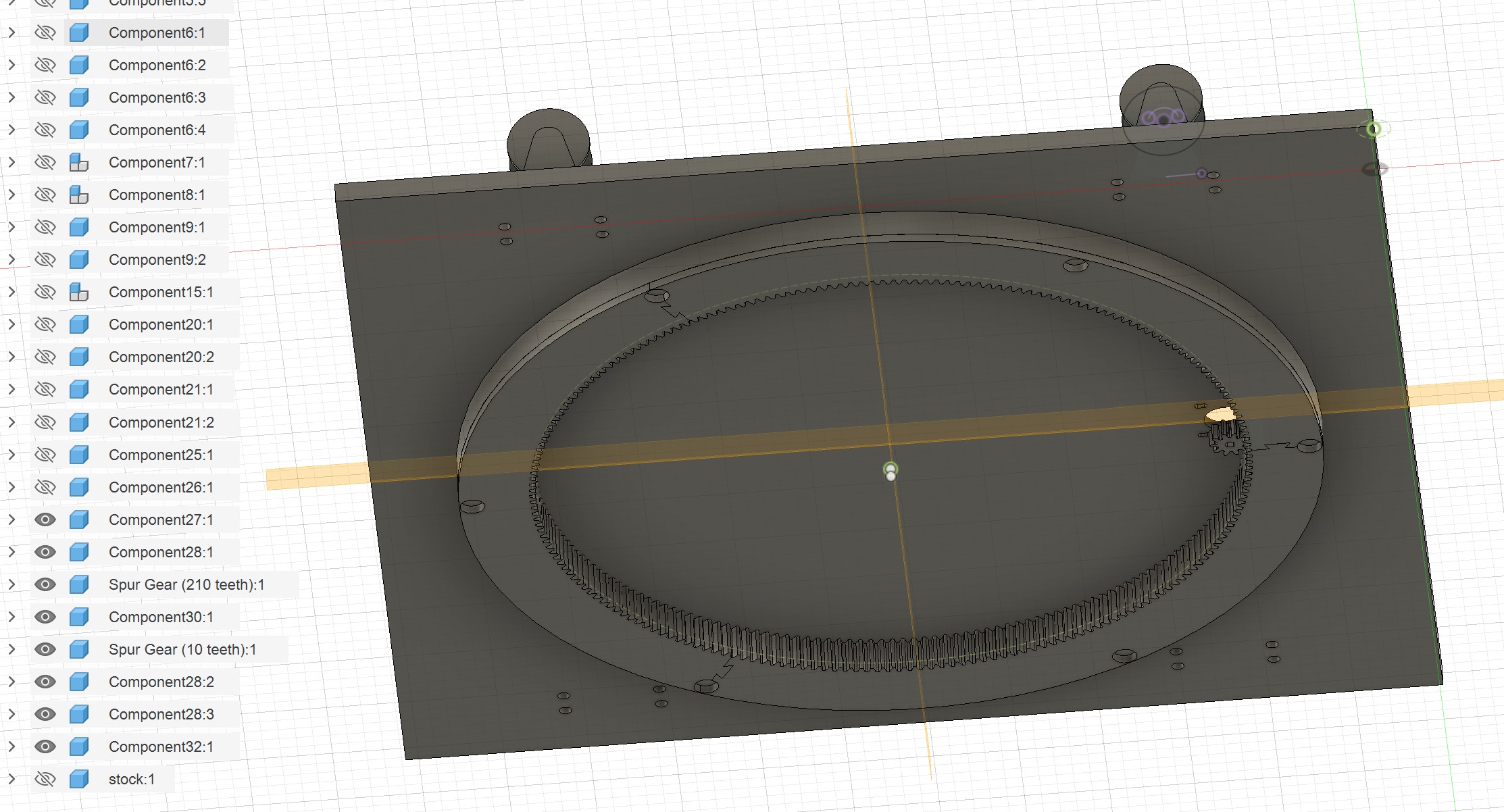
To 3d print the strongest gear, I used the PETG-CF filament and applied 95% filling rate in the first printing test. However, it was not smooth, since the too high filling rate caused the extra extrusion and the waste material stuck on the nozzle, finally causing the nozzle clogging. To solve this problem, I adjusted the filling rate to ~50%, but increased the wall layers to 10, which can still ensure the mechanical strength. One piece requires ~4h to print with ~200g filament, which is not as bad as I thought. Here is the photo of the finished big inner gear:
To machine the base plate, I used Fusion again for 3D CAM, and then used the ShopBot in the CAB shop to CNC the wood plate. I used a 3 mm end mill, but the smallest hole is 3.5 mm in diameter, so I struggled on the CAM setup to allow it to generate the tool path for those small holes.
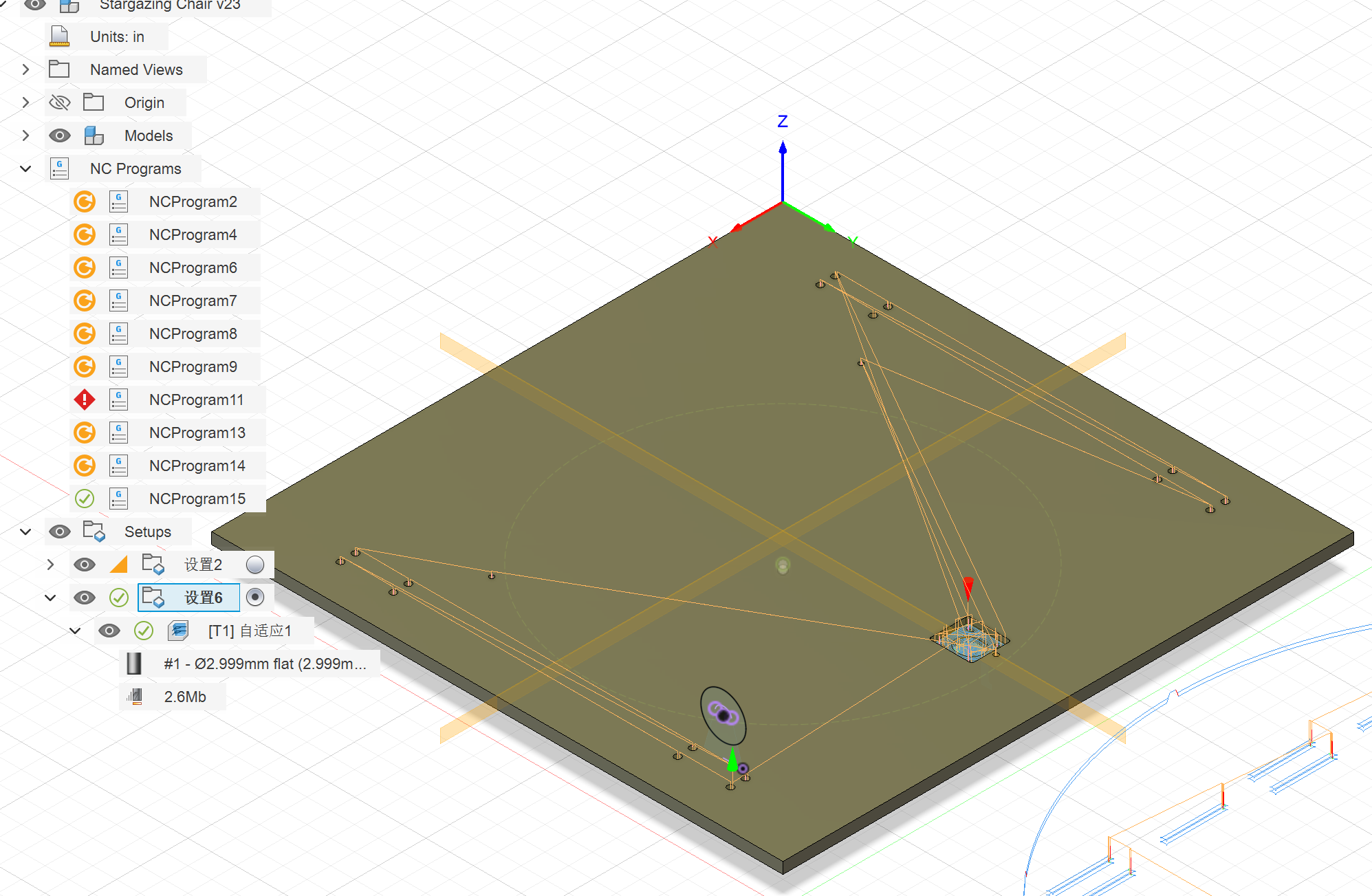
I ran the CNC twice, while one time can consume me one hour. It’s because I forgot to open the spindle the first time, and it hit the stock, shortening the end mill and changing the Z-axis zero position, but I didn’t notice that. As a result, the first attempt didn’t give me a deep enough cut.
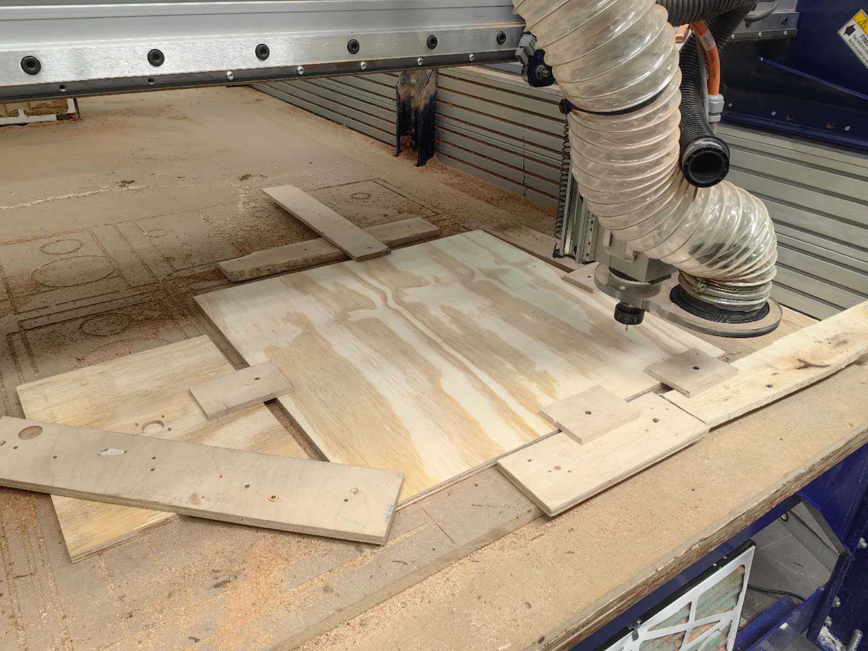
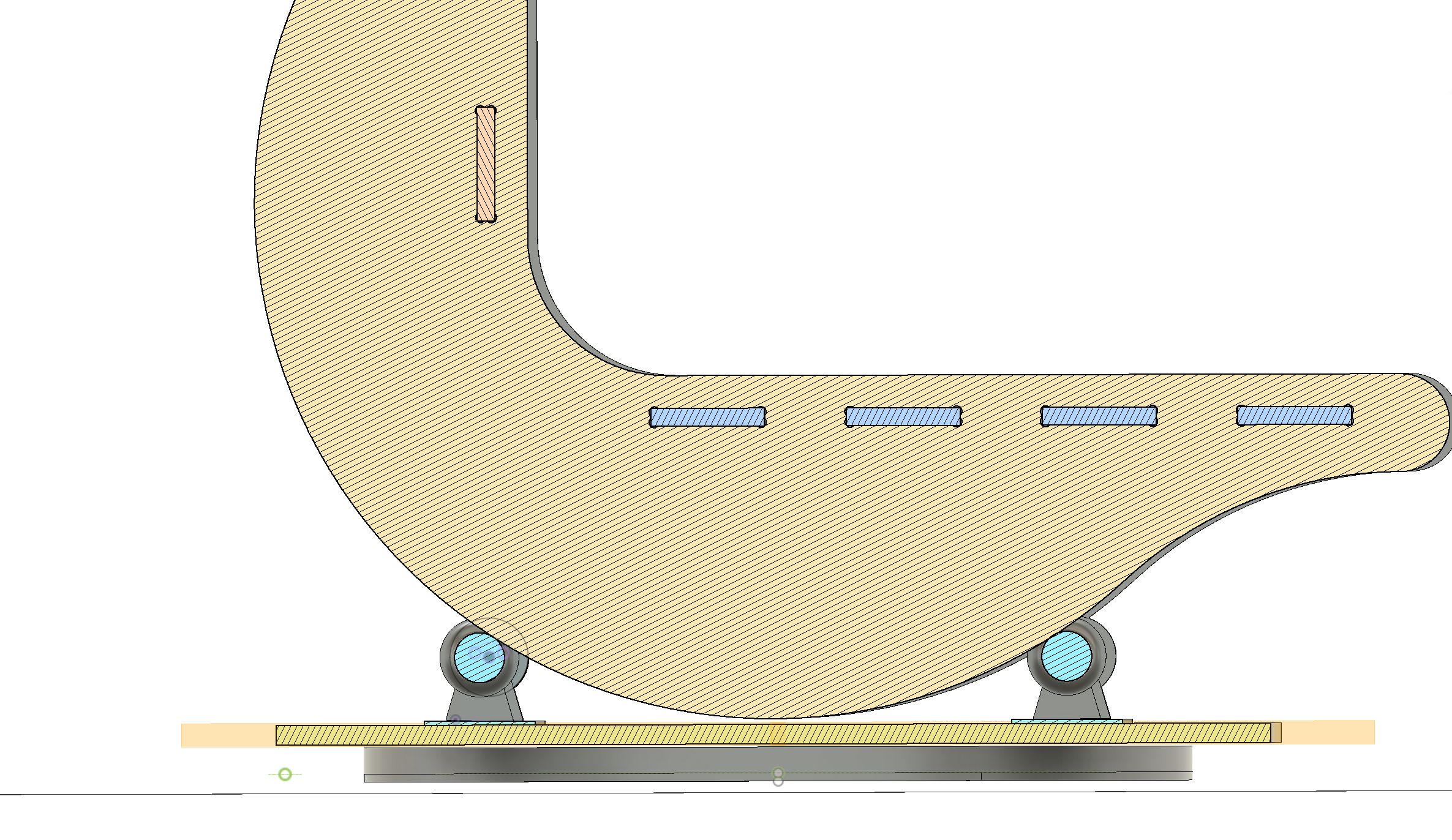
But the final result came well! I installed the gears, the motor, and the wheels; it rotated smoothly. The positions of the four wheels were simulated first in the CAD, and the assembled chair matched perfectly with the simulation:
9. The development of the hand controller for the stargazing chair
The functions of this hand controller are to control two motors (ideally, but only one is available on the chair), and also include an OLED screen, a GPS module, and several buttons to control the speed and direction of the motors.
There are three different voltage levels: 3.3V for the logic, 5V for the MCU power, and the GPS modules’ power; 12V for the general battery input and the motors. I need to fly lots of wires. Here is how it finally looks like:
During the fabrication of this board, I noticed the MCU couldn’t be detected by the computer first, so I debugged and then figured out the RUN pin (for reset if the voltage of that pin is pull down) was wired with ~2.3V (should be 3.3V to start the MCU normally)pulled. So I used the drills to remove that pin connection to the button. Then the board can work! The vedio here showed my first motor test with 12V power station from the electronic lab, and I can click the button to change the speed.
When I load the motor on the actual chair, it can still rotate under the lowest speed. However, when I sit on it, it can't rotate anymore! I guess the current limitation was set too low so the torque of motor is not strong enough
After these electronic design and the final demo, I also explored the mobile interfaces for my final project. It is discussed on the week 13 documentation: (Interface)
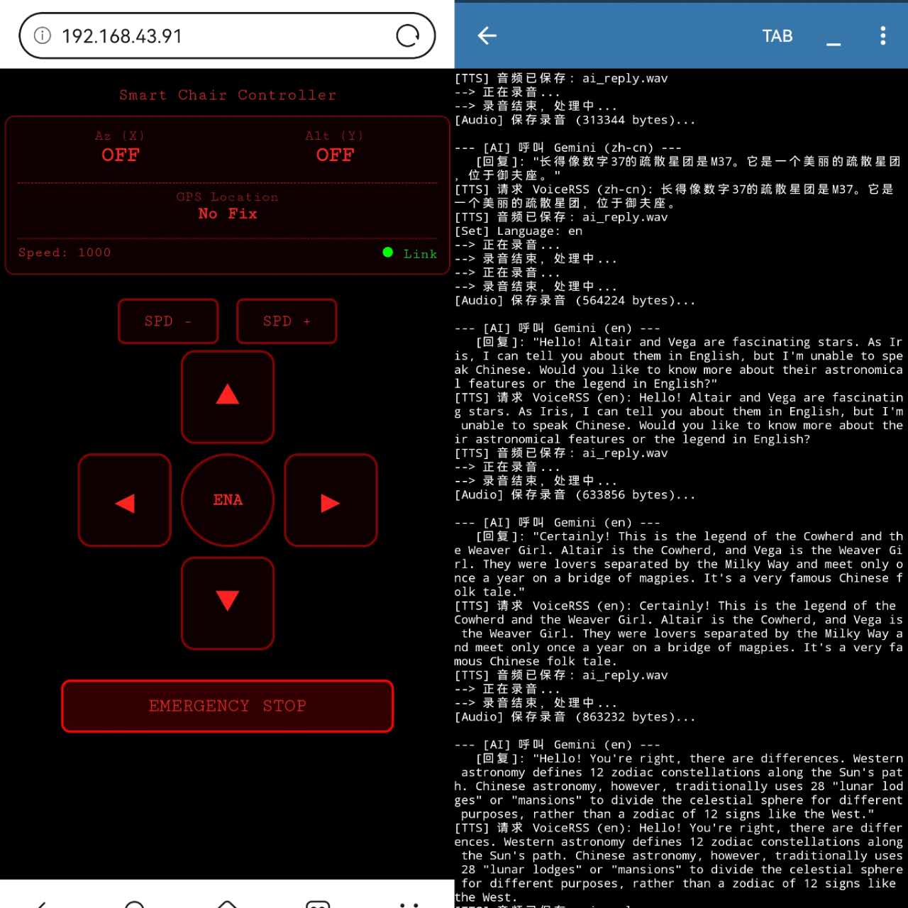
With that, my final project is basically done! The python server script can be ran on the phone now, and the motor controller can be ran on the phone browser through HTML. I fianlly get rid of the computer and it's ready to be tested under the wild night sky!