The UCBus
A duplex bus using UART over RS485. Provides time division recieve from multiple drops, drop addressing (and broadcast packets), packet delineation, and flow control in both directions.
Physical Topology
This is something I developed starting around August of 2020. I knew I wanted a simple type of bus, because it had become obvious that quality motion control requires some kind of broadcast packet. This requirement more or less nailed down the bus topology: I would have one “head” (or host) on the bus (this is where motion control / acceleration planning would happen), and then multiple “drops” (or guests).
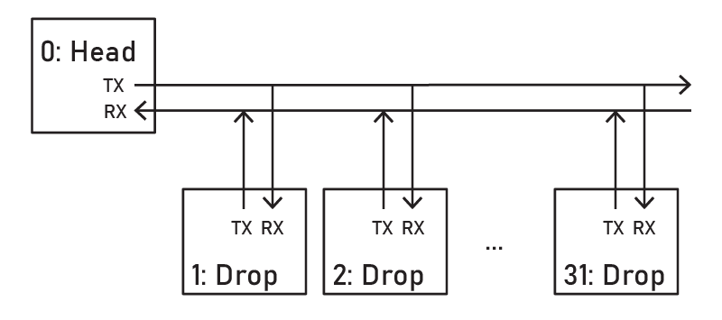
The head is always able to transmit to the drops, and transmissions are broadcasts by default: anything they put on their TX line is seen on all of the drops’ RX lines. This allows broadcast of motion control packets, synchronization, etc.
However, drops all share one transmit wire, i.e. the head can only recieve data from one drop at a time. This means (to start) that we might have 1/30th of the “uplink” bandwidth as we have on the “downlink” - and we will have to divide time on this shared medium under some scheme. However, there’s sort of no way around this unless we were to add one new rx line per drop.
Electrical
The bus uses RS485 voltage levels. This is an extremely common spec for differential signalling in small networks.
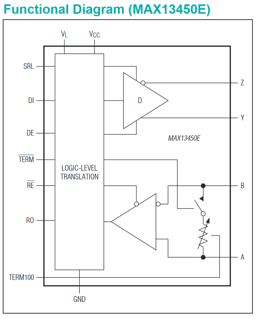
This means that each member needs some RS485 tranciever (they are cheap, and extremely common), and also that we need to deal with termination resistors - these are basically impedance balancers that live at the end of an electrical link that minimize reflections:
The drivers that I use have a built-in, software selectable termination resistor. I operate this with the DIP switch (noted below) or in firmware, so that I can “configure” my busseses such that only one termination resistor is on.
Addressing
This is dead simple: we have 5 bits of “address” information in each data frame (as we will see later), so ostensibly 32 bus positions. However! For reasons, we say the bus “head” has address 0 and so drop addresses from 1:31 are viable.
Addresses are static! To configure them, we can initialize the bus drop with some custom address / ID in firmware:
void ucBusDrop_setup(boolean useDipPick, uint8_t ID);
Or we can use a DIP switch. I put these little ones on most of my circuits:
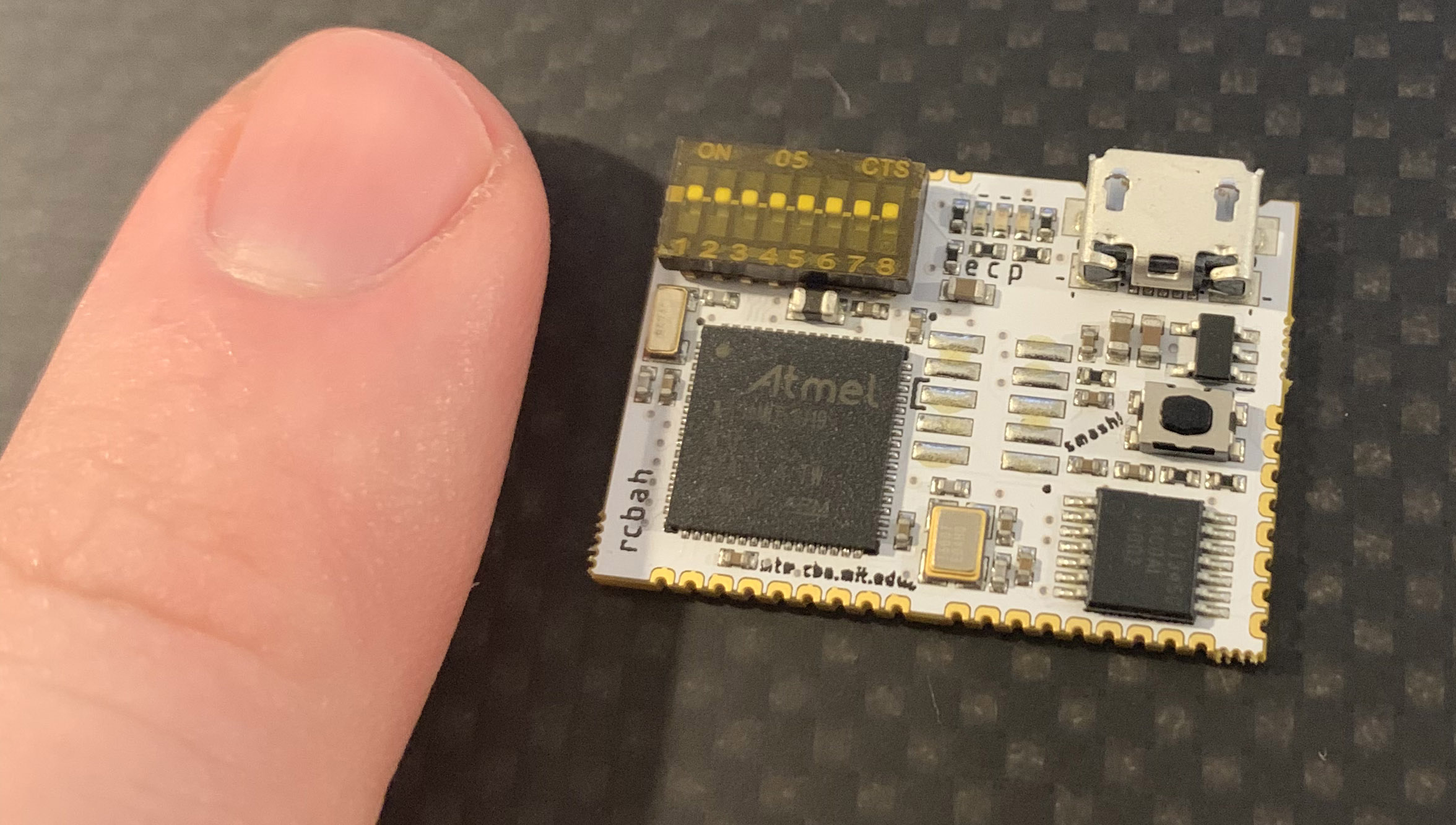
In this case the bits labelled as 4:8 are configured as “address bits” and are read into code on startup.
Clocking
So far we just have a straightfoward RS485 full duplex bus. But here is where it becomes strange: even if there is no data to transmit, the head will generate data words every 20 microseconds (50kHz). Data words are then further “stuffed” and can be marked with a “token” (meaning that they are data-ful).
Deterministic transmission of something at a known rate means that bus drops can use the RX interrupt as a clock tick. When my machines step, they do so on this “UART Clock” and so are fairly well guaranteed (+ / - whatever difference in their interrupt handler speeds are: probably nanoseconds) to tick at the same time. I could do the same (possibly dividing the clock) to run i.e. control loops, or I could count the intervals to time-stamp data queries, etc.
The clock can be reset (drops’ counters are zeroed) when the head “transmits” to drop 0 - which doesn’t exist.
Frames / Words
Note: you don’t need to understand this section in order to use the bus.
I transmit one frame every 20us, where a frame consists of four bytes. The byte is the unit most UART periperhals will read / write. I am using the 32 bit extension in the SAMD51’s UART peripheral, but all this does is allow me to read four bytes (or write four bytes) per interrupt: there are indeed still four stop bits during these transmissions.
Now, there’s a bit of a trap here: since the recipient is unable to properly align each frame (there are four stop bits) we have to distinguish each byte in the four-byte word from one another. As a result, each individual byte is structured like this:
| B0:1 | B2:7 |
|---|---|
| 2 bit byte ID | 6 data bits |
If this seems asinine to you, I think you might be right. We’ve already knocked 1/4 of our raw data rate away to simply ID individual elements in a word? This approach is stateless: meaning anytime a drop appears on the bus, it can immediately (on first successful interrupt / receipt of some byte) begin to form packets. It doesn’t need to handshake with anyone, establish itself in byte-order, or whatever else. Also, if bytes are ever dropped, frame tracking is not lost.
So, we have four bytes per frame, meaning that (two id bits per byte) we have a full (2x4) byte taken up in our frame taken up to ID bytes. The next half of our overhead goes to drop addressing and token-izing frames. This is the header byte and is structured like so:
| B0:1 | B2 | B3:7 |
|---|---|---|
| Token (word contains 0, 1, or 2 bytes) | Channel (0: A, 1: B) | Drop “Tap” |
After this, the following bytes are data-carrying. The token denotes how many of these contain data. The third bit in this header is the channel indicator: we have a high priority broadcast channel A for motion / realtime data and a low priority info channel B.
Bits B3:7 in the header denote which drop is being “shoulder tapped” on this frame cycle. This is how time is divided on the head’s RX line: when the drops recieve this frame, if their ID / address matches this number, they will take the opportunity to transmit a frame to the head. Now, if we have all unique ID / addresses on the bus, we will not collide incoming frames. Again, this is a stateless approach: time division happens at the frame level meaning we don’t need a series of packets to determine when / how drops are able to transmit without colliding.
So, we effectively have four “bytes” inside of one frame: one is taken to delineate bytes within the word, another is taken by the header, and the last two are real data bytes.
These are interleaved as follows:
| B0 0:1 | B0 2:7 | B1 0:1 | B1 2:3 | B1 4:7 | B2 0:1 | B2 2:5 | B2 6:7 | B3 0:1 | B3 2:7 |
|---|---|---|---|---|---|---|---|---|---|
| 0:1 | 2:7 | 8:9 | 10:11 | 12:15 | 16:17 | 18:21 | 22:23 | 24:25 | 26:31 |
| 00 | H 0:5 | 01 | H 6:7 | W0 0:3 | 10 | W0 4:7 | W1 0:1 | 11 | W1 2:7 |
Drops transmit the same style frame to the head.
Packet Delineation
Any data link layer needs a way to distinguish the “end” of a packet. Here, because we have a token nibble, end of packet (EOP) is simply the token edge: whenever a channel which previously transmitted a non-zero token transmits a zero token, we know that proceeding bytes formed a full packet, and can handle it.
Channels / Addressing
As noted above, we have two channels: A and B - many more complex busses have ~ 8 levels of priority information. Here, A is high priority information and is always transmitted first, whenever it becomes available while B is transmitted whenever dead space exists on the bus.
Each channel is packet delineated. Channel A packets are pure datagrams - each byte is application level information.
Channel B packets contain additional information:
| Byte 0 | Byte 1 | Byte 2 | … | Byte N |
|---|---|---|---|---|
| Drop Address | Flowcontrol | Data Byte 0 | … | Data Byte N |
All drops recieve all Channel B packets, but only drops with an address / ID matching the first byte here will handle the packet, all others will ignore it.
Byte 1 in each of these packets is flowcontrol information, which is covered later.
Time Division
As noted also in the framing section, each frame contains a 5-bit address / ID. The recipient whose ID / address matches this number uses that frame-cycle to transmit to the head. This way, no drops will attempt to transmit to the head at the same time, and our shared recieve line is successfully shared amongst drops.
Flow Control
When we are transmitting to any networking partner, we want to know ahead of time whether their compute / application is ready to handle a new packet. This is not guaranteed to happen in fixed / deterministic time at any bus drop (or head) and so we need to share this information across the bus.
To do this, the UCBus takes advantage of dead space (data bytes w/ no matching token) in each frame. Essentially, whenever a frame has dead space within it, the last data word in that frame is a reciprocal rx buffer space count - you’ll find this number in code denoted as rcrxb. This is the transmitter’s count of empty buffer spaces which the current frame recipient could transmit into.
This means that everyone on the bus passively recieves information about whether/not they are clear to transmit towards their partners, and because this happens largely outside of packets, we don’t waste space (that isn’t already wasted) transmitting this information, and we don’t need a full packet (delineated) in order to do so.
However we have a corner case where not many empty spaces exist on the bus, under full utilization. So we additionally stuff the second byte of channel B packets with this same information, to guarantee that it is transmitted whenever a packet is formed.
Resulting Data Rates
We see that the resulting performance seems weak relative to the base bitrate. Recall that we are using 1/2 of our bandwidth with framing (and addressing, and flowcontrol) overhead. The cost of this seems large, but the advantage is a stateless (and so, deterministic) bus. There is no setup time, drops can be hot-plugged without interrupting other transmissions, and flowcontrol information is transmitted largely “instantaneously” outside of delineated packets.
The drop -> head bandwidth is additionally lowered by time division: uplink speed is divided by the number of possible busses. A smarter “bus head” code could improve this by tracking which drop positions have actively transmitted recently, and dividing time only between active drops.
| revision | base bitrate | frames / second (kHz) | gross frame size (bytes) | data frame size (bytes) | interrupts / second (kHz) | address spaces | head -> drops | drop -> head |
|---|---|---|---|---|---|---|---|---|
| 8bit | 1M | 25 | 2 | 1 | 50 | 15 | 200 kBaud | 13.3 kBaud |
| 32bit current | 3M | 50 | 4 | 2 | 50 | 31 | 800 kBaud | 26.6 kBaud |