2.4 GHz antenna
Printed dipole
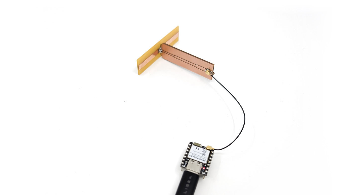
Putting all of the results together, I decided to fabricate a dipole antenna with an operating frequency of 2.44 GHz, to succesfully communicate with WiFi devices. My design is slightly convoluted, and includes coplanar waveguide transmission line, a quarter-wave impedance transformer going from $50~\Omega$ to $75~\Omega$, followed by a printed dipole antenna soldered at 90°:
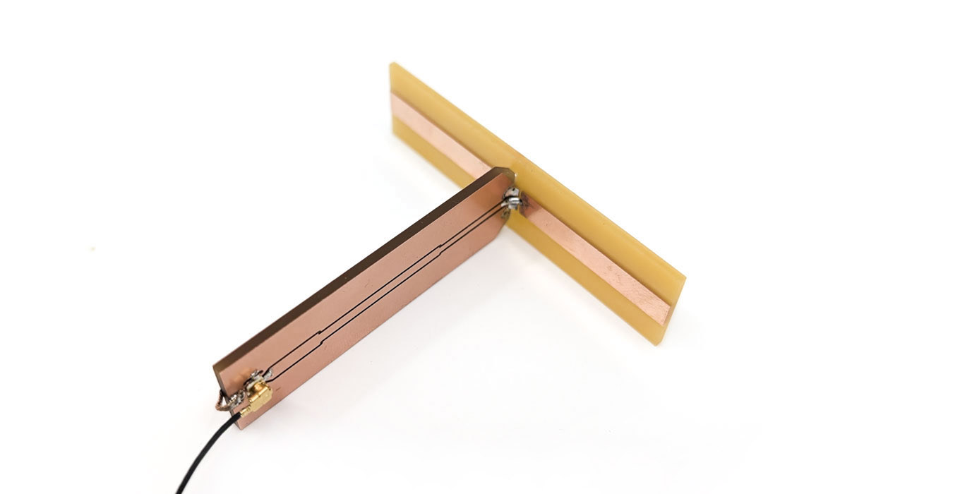
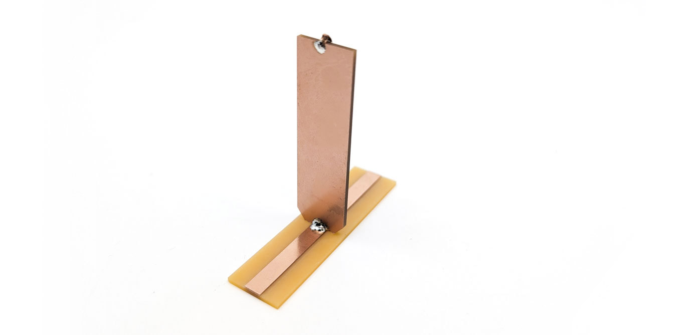
The dipole was fabricated on a single-sided FR1 substrate, as there should not be any ground plane behind it. The assembly is very sturdy, thanks to solder joints on both sides. Also note that this joint connects the top and bottom gound planes of the coplanar waveguide line.
Results
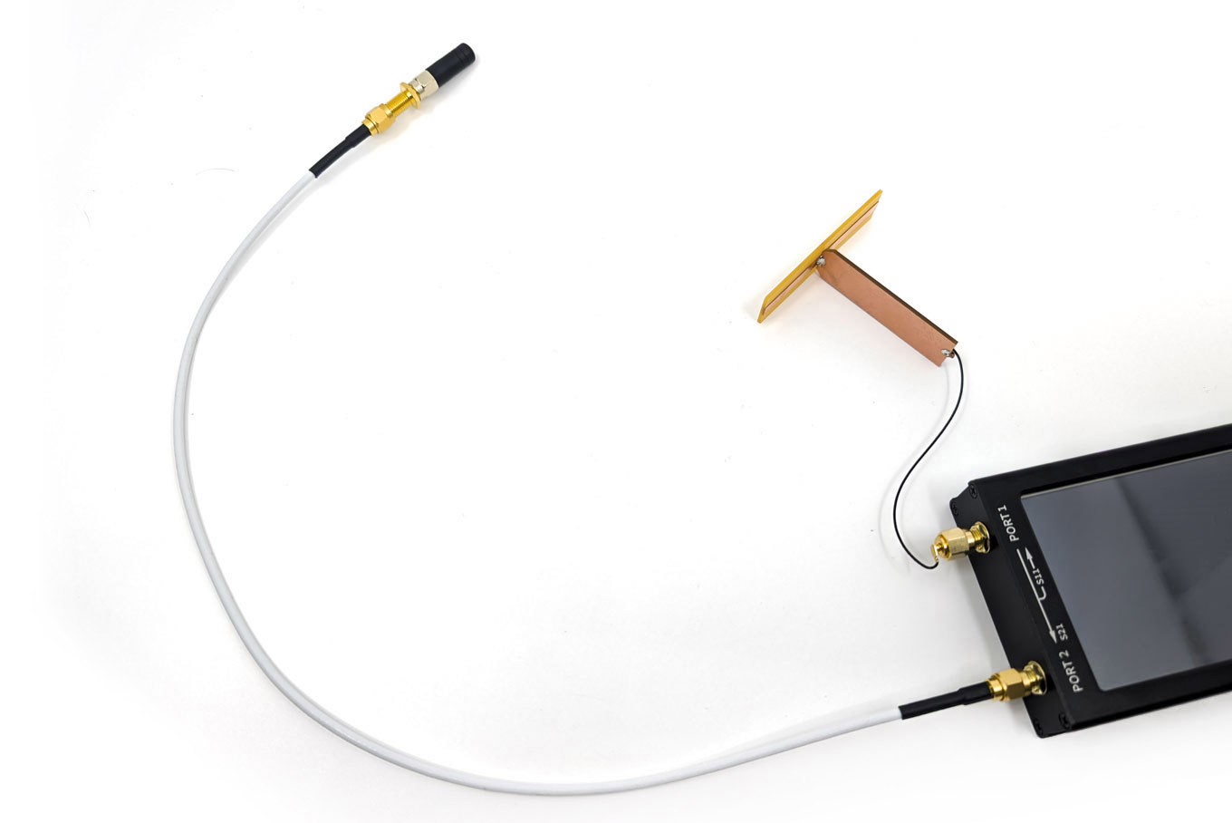
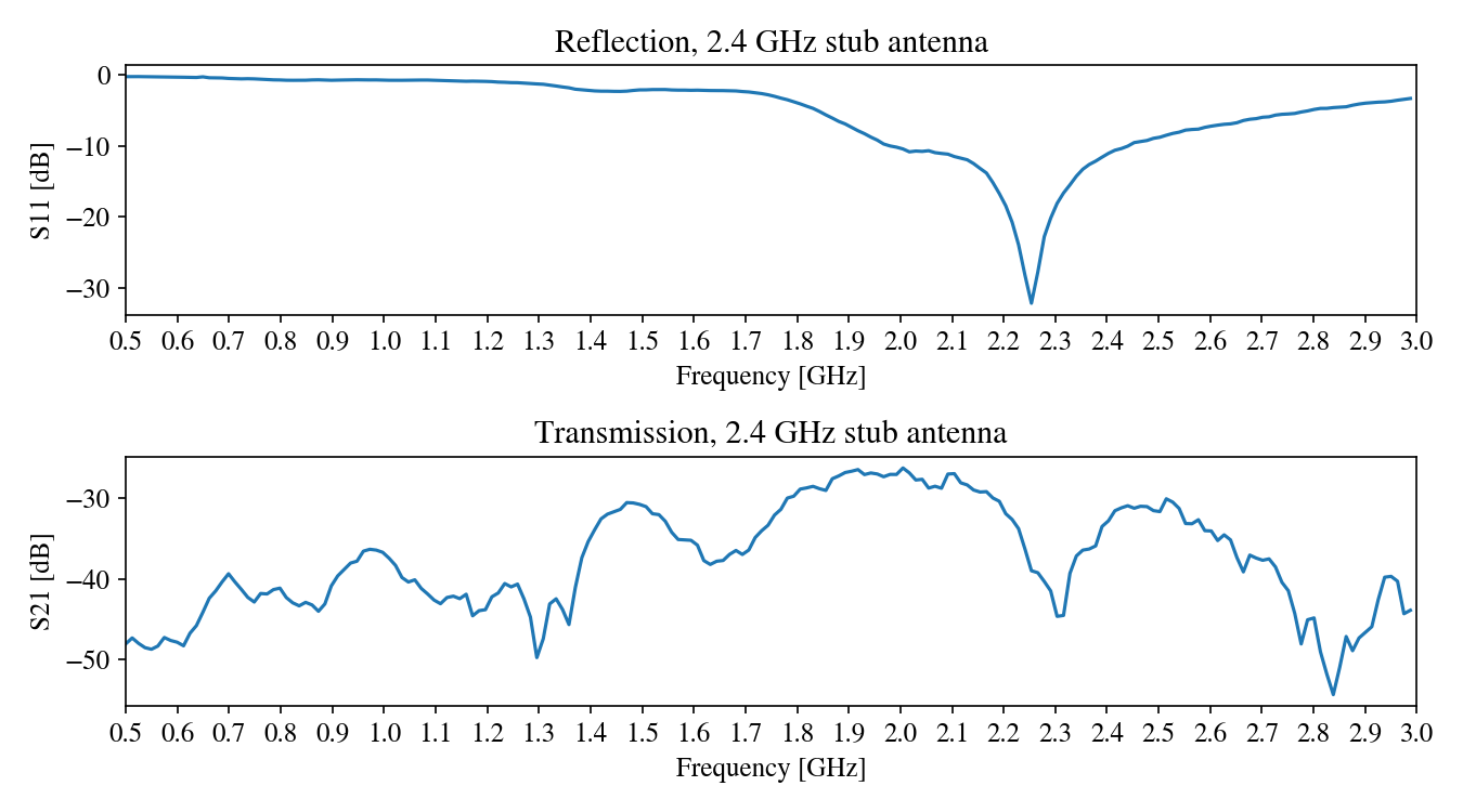
Measuring antenna responses with a VNA is a bit tricky. I used a commercial 2.4 GHz WiFi stub antenna to have a decent estimate of the transmission at the band of interest:
The result shows two dips in reflection loss: one around 2.4 GHz, as planned, and another one at a lower frequency. Unfortunately, the design of this antenna is rather naive, so there might be radiation modes caused by the total length of the conductor. To counter this, a balun circuit would be a good start, and a better grounding around the waveguide (with vias) should be implemented.
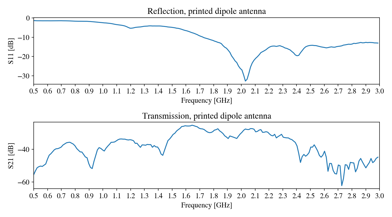
The transmission still looks decent around 2.4GHz, which is what matters for this project. For comparison, here are results when replacing our antenna with another commercial stub antenna:
Finally, I put the antenna to the test by connecting it to an ESP32 microcontroller:
The antenna works well for WiFi transmission. Here is the result of a WiFi scan, showing the RSSI for each network:

For comparison, here is the result with the commercial antenna:

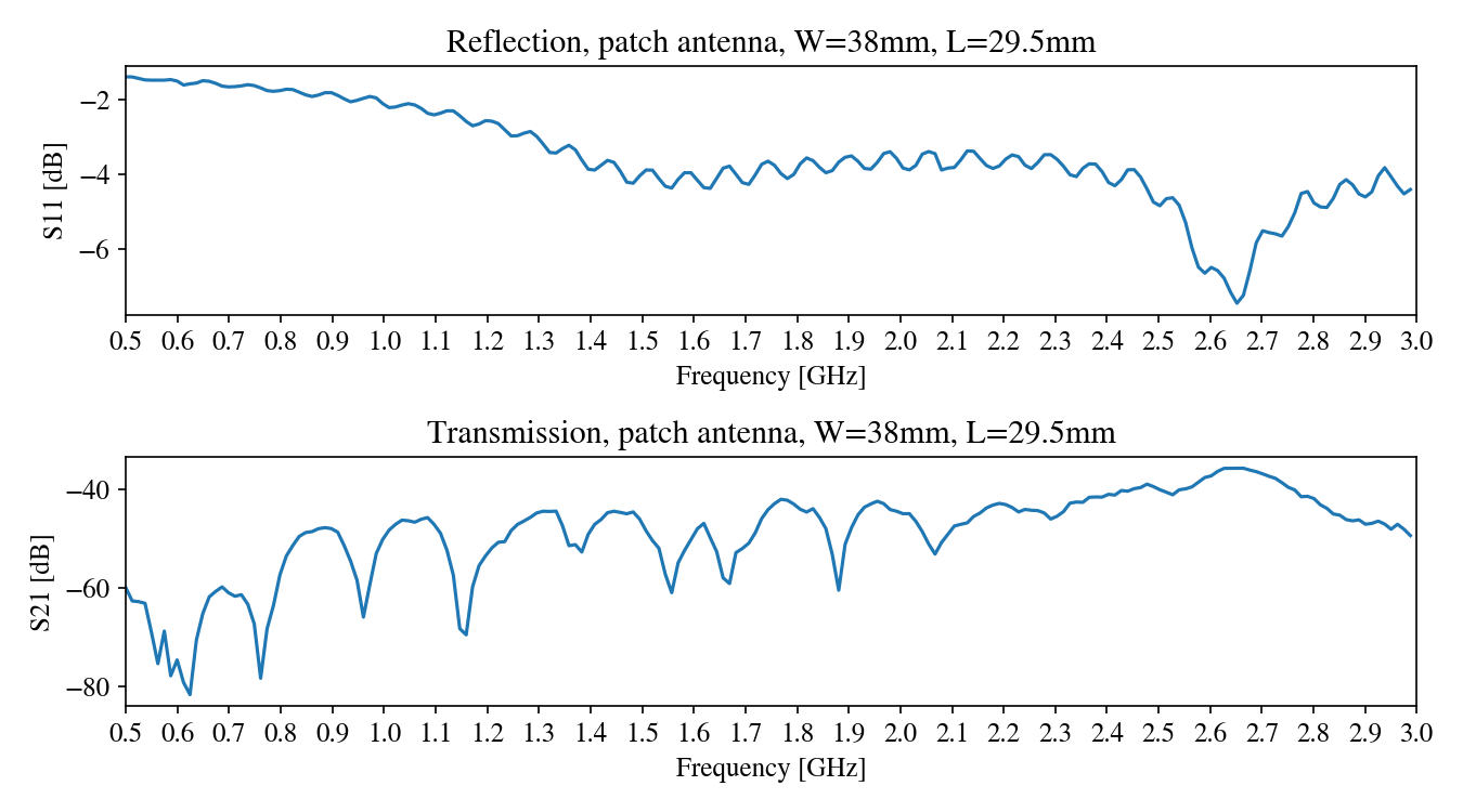
Patch antenna
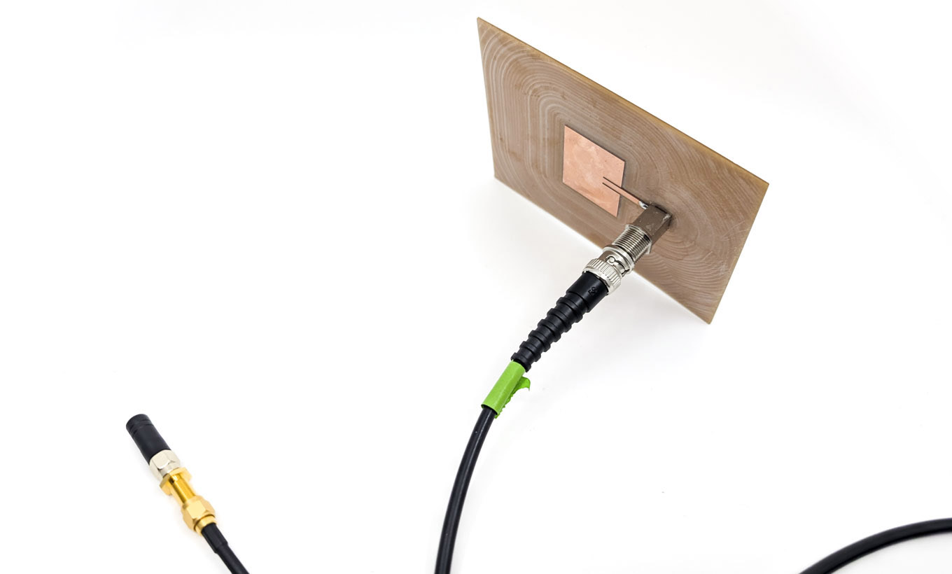
As a bonus, I also tried to make a patch antenna:
The plot shows a peak much too high, around 2.8 GHz: