
Input Devices
Group Assignment
1. With my group I probed an input device's analog levels and digital signals.
Fellow architecture section student and class TA Niklas Hagemann created a capacitive sensor and used the oscilloscope's trigger function to take a snapshot of the discharge of the capacitor (Fig. 1A). Niklas kindly shared his results with the rest of the class.

Fig. 1A. Capacitive sensor readout on oscilloscope.
I will likely be doing a lot more signal processing in the next several weeks, so this was a good introduction!
Individual Assignment
1. I tested the buttons on the microcontroller board I designed and further developed the circuit for my final project.
In Week 06 I created a circuit board that simulated the functionality. This week, I tested the input components of the circuit board by adding a sensor to my connector to see if it works.

Fig. 1A PCB Design from week 6
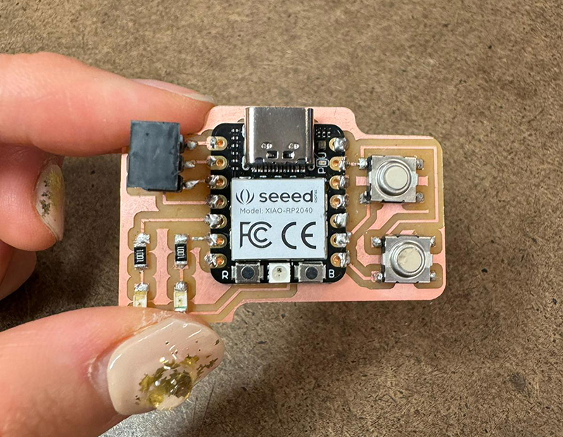
Fig. 2A The finished board with all the parts soldered

Fig. 3A Small Force Sensitive Resistor
For the sensor input, I decided to test with a small Force Sensitive Resister that I own.
Here is the specification of the sensor from the website 06
"It has a 0.16" (4 mm) diameter active sensing area. This FSR from Interlink Electronics will vary its resistance depending on how much pressure is being applied to the sensing area. The harder the force, the lower the resistance.
When no pressure is being applied to the FSR, its resistance will be larger than 1MΩ, with full pressure applied the resistance will be 2.5kΩ."
Fig. 4A. Arduino code for testing each components.
This is after I've hooked it up to the PCB board. Ideally, I shouldn't need an extra breadboard but...
Yes, I think the sensor could've been connected in a cleaner and prettier way. But for the purpose of testing input signals for this assignment, I guess it works!
                    const int led1Pin = D4;
                    const int led2Pin = D5;
                    const int pressurePin = D0;
                    const int serialSpeed = 9600;

                    int pressureState = LOW;

                    void setup() {
                      pinMode(led1Pin, OUTPUT);
                      pinMode(led2Pin, OUTPUT);
                      pinMode(pressurePin, INPUT);
                      Serial.begin(serialSpeed);
                    }

                    void loop() {
                      pressureState = digitalRead(pressurePin);

                      // Check pressure sensor input and control the LEDs
                      if (pressureState == HIGH) {
                        // Pressure is detected
                        digitalWrite(led1Pin, LOW);
                        digitalWrite(led2Pin, HIGH);
                      } else {
                        // No pressure detected
                        digitalWrite(led1Pin, HIGH);
                        digitalWrite(led2Pin, LOW);
                      }

                      // Read and print the pressure sensor state to the Serial Monitor
                      Serial.println("Pressure State: " + String(pressureState));

                      delay(1000);  // Delay for 1 second between readings
                    }
To explain the code above, LED1 (Green) will be on (with LED2(red)) off when no pressure is detected, and LED2(red) will be on if pressure is detected from the sensor.
Fig. 5A Input signal test
The video above demonstrates the LED lights switching when I press the force sensor with my fingers. When I undo applying pressure, the default green LED turns back on.
Fig. 6A Serial monitor
The serial monitor above is showing 0 for no pressure detection and 1 when it detects pressure.
Since this force sensor's resistance ranges from 1MΩ to 2.5 kΩ, I can potentially adjust the logic and detection range to get different pressure levels, and have the LEDs blink in different speed based on the range of force detected. I will also try switching to 3.3kΩ resistor(recommended from the website) from 1k which I used. I am currently working on it, and will share an update.