Sound is hard. It required programming I don't know or understand.
Week 09
Input devices
Software Tools: Autodesk Fusion 360 (aka Autodesk Eagle), Universal Gcode Platform (Version 2.0.20) to send the gcode file to the milling machine, Quentin's online gerber to image tool, and Professor Neil's modsproject online tool to create a gcode file.
Hardware Tools: Genmitsu milling machine
Previous experience: Board design experience from week 06
This week can be broken down into three phases:
- Designing a board with a microphone
- Milling the board and soldering the components on
- Reading the outputs of the microphone
Video of the microphone capturing sound and music in the office
Designing a board
I needed help this week. I went to two office hour sessions, watched YouTube videos, and drew inspiration from past projects. Specifically, I utilized the following resources:
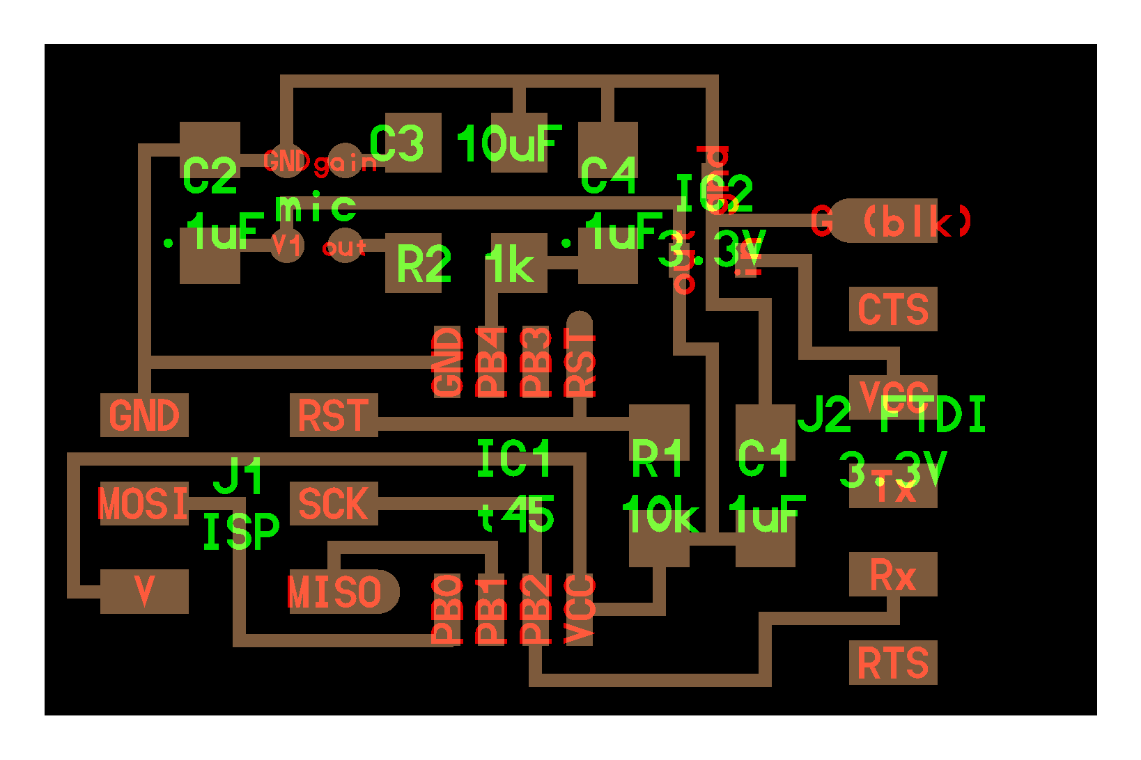
- A board design with the analog microphone SPU0414HR5H on MAS.863 page
- Data sheet for the microphone "Analog SPU0414HR5H-SB-7"
- An online forum with links to projects with the Raspberry Pi Pico W board and a microphone
- Yosuke Tsuchiya's final project page from 2019
- Shinobu Ishimura's week 10 page from 2021
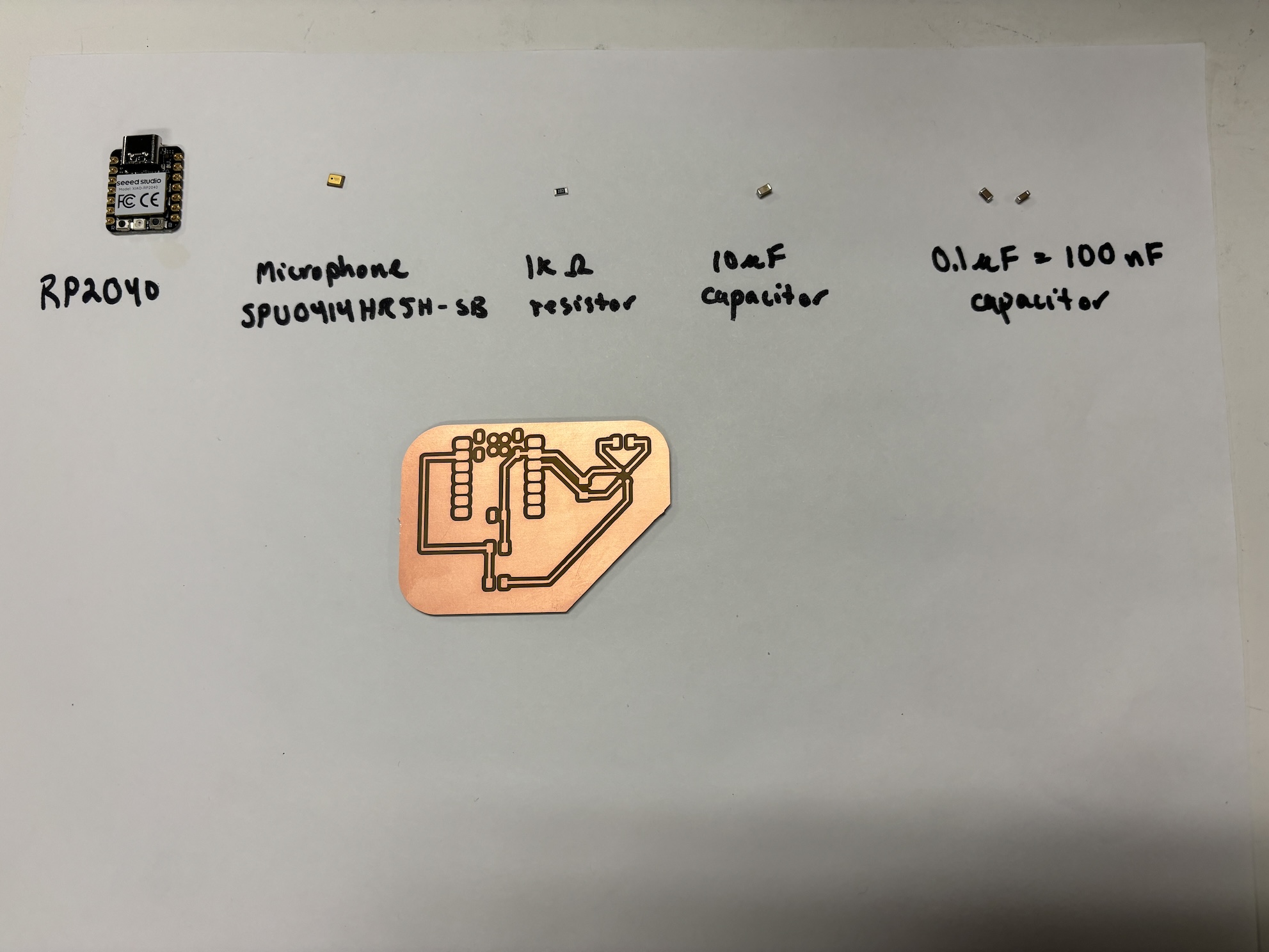
Referencing the resources above, I designed a simple circuit board with the Analog SPU0414HR5H-SB-7 microphone, a resistor, three capacitors, and a Xiao RP2040 microcontroller.
I followed the process I documented in Week 06 Electronics Production to create gerber files and gcode files of the board traces and edge.
Here are the files I created for easy reference:
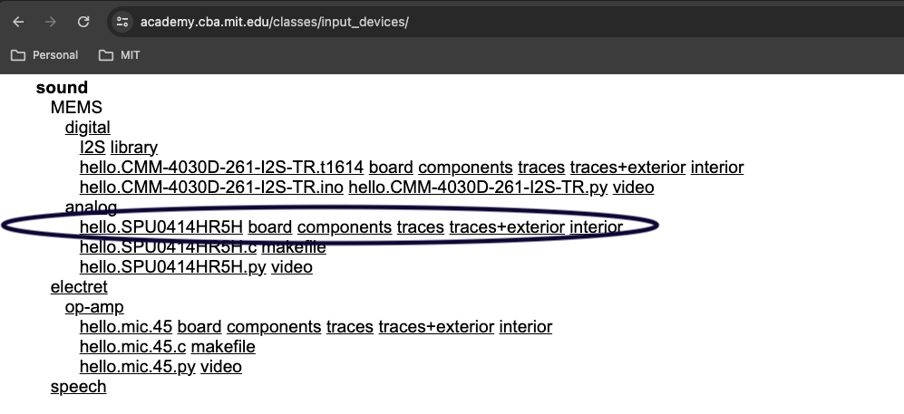
Screenshot of the class website for week 09, input devices
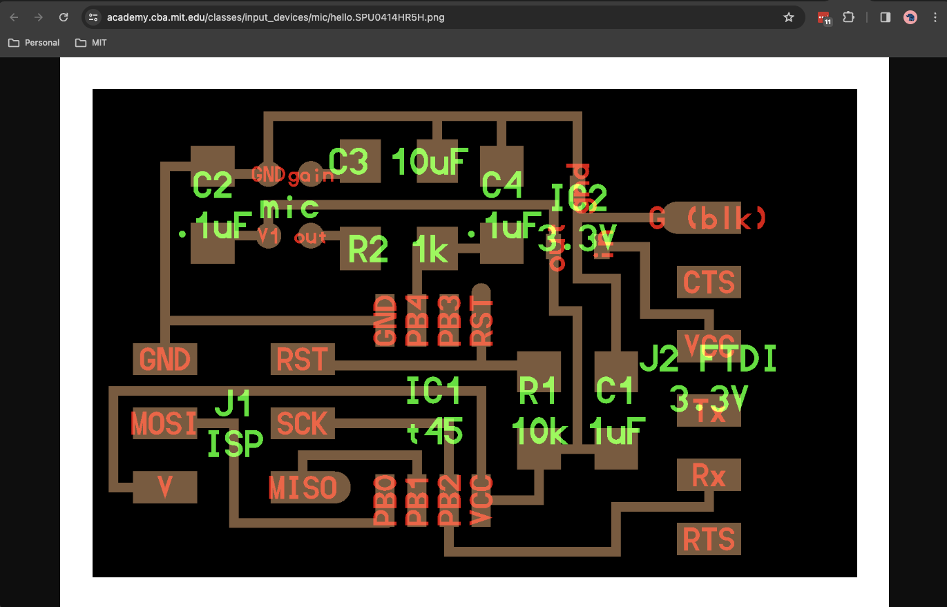
Neil's board design for inspiration
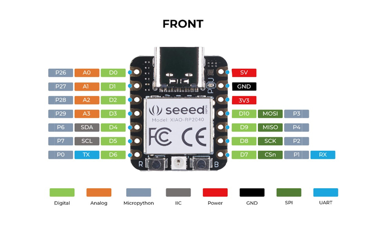
RP2040 pins
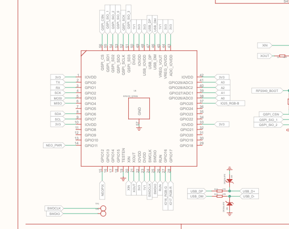
RP2040 schematic. Link to RP2040 Wiki
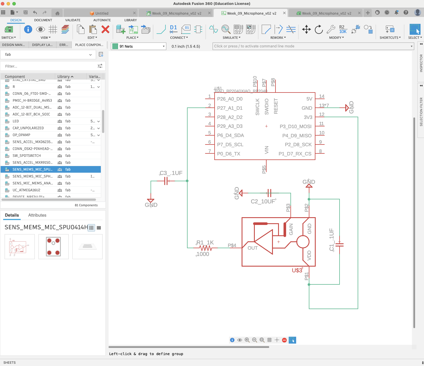
The first schematic of my board design
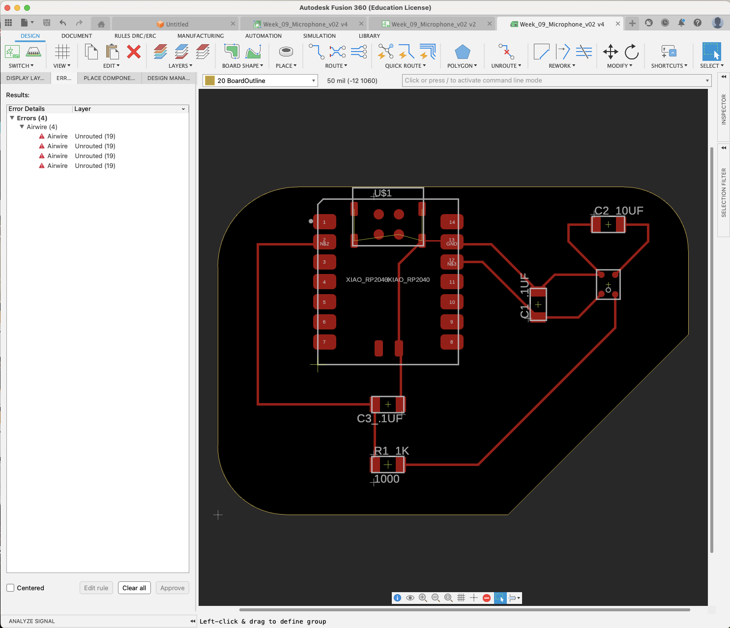
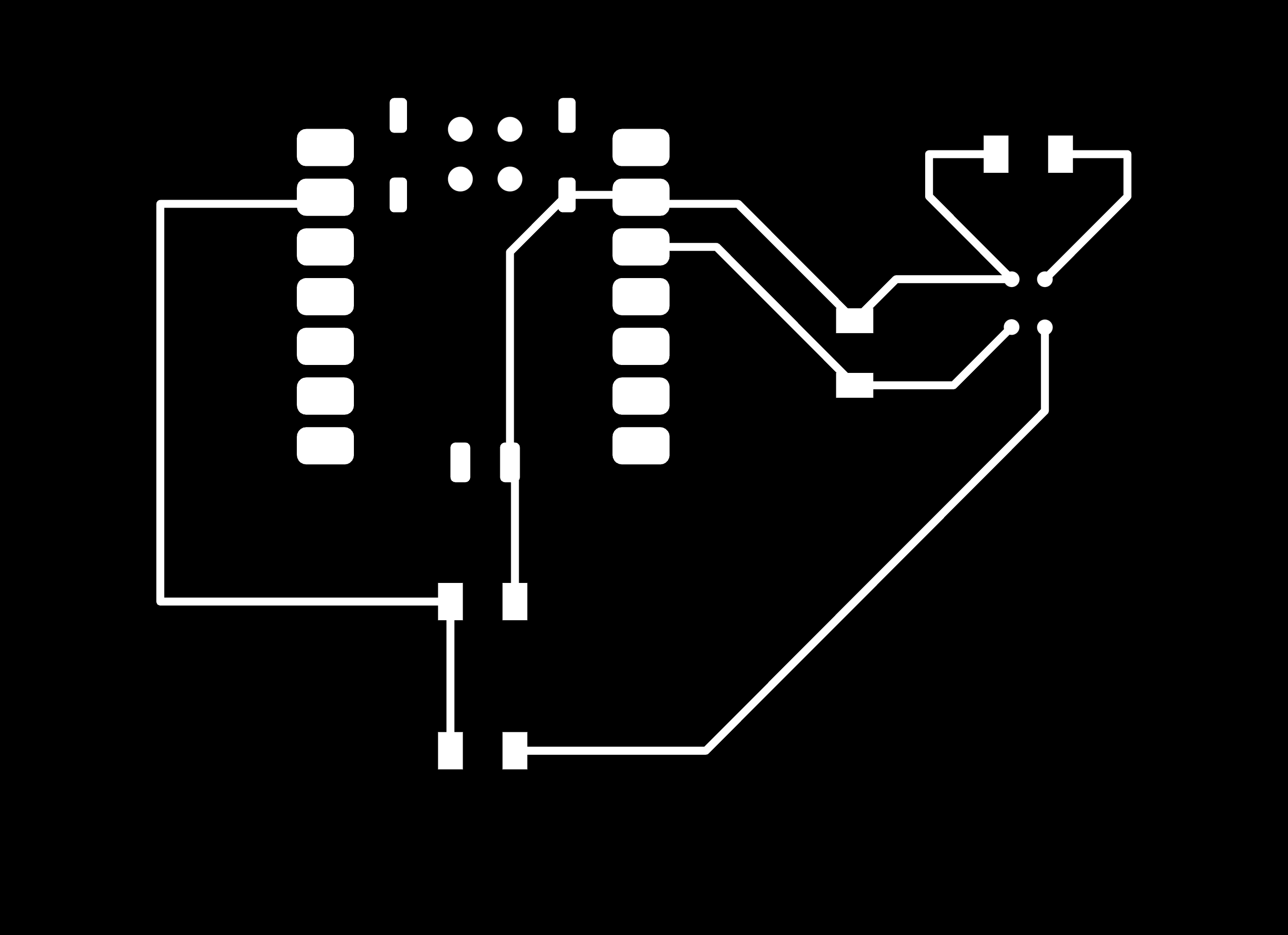
The first PCB for my design
Milling a board
I used the Genmitsu milling machine in E15-043 with the Universal Gcode Sender software on the adjacent desktop machine.
When I arrived, the software program was not open, but my trusty peers in the cba shop shared their past class website with me
which included instructions for starting the program!
I followed the instructions on Vincy Xiao's Electronics Production page from 2023:
- On the desktop, enter
Ctrl + Alt + T - In the terminal, type
cd Desktop/ugsplatform-linux/bin/ - type
./ugsplatform - This should open the Universal Gcode Sender program. Then I opened my gcode file.
I followed the process I documented in Week 06 Electronics Production to
mill the board. The only difference this week is that I used double-sided tape to secure a new board on the sacrificial board.
I felt comfortable using the machine, zeroing the z-axis, and finishing the board. There were no issues.
If needed, this website has a good guide on how to use the "UGS platform".
These are the steps I followed to run the milling machine:
- Click “Open” - select my gcode file (.nc)
- Check if the drill is the right one (1/64” for traces, 1/32” for edge cutting)
- Click “macro” -> “[1] Raise Z”
- Setup the grounding cables, and click “macro” -> “[2] Probe and zero Z”
- Position the drill to the right position and set X0 and Y0
- Press the play button that reads “send” and start milling
- Turn on the vacuum cleaner and wear ear mufflers or noise-cancelling headphones
- Repeat the steps above for the edge of the board
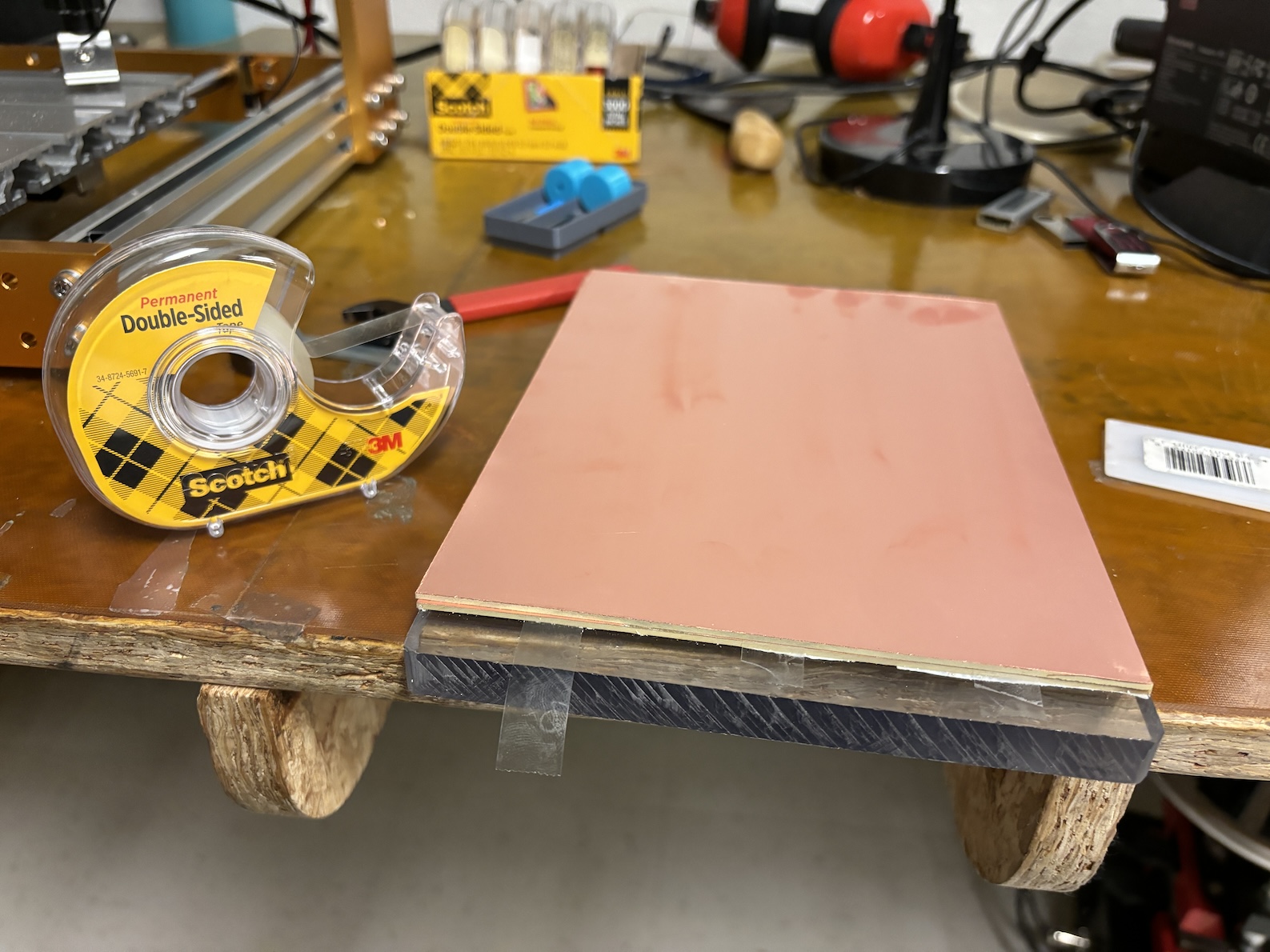
Using double-sided tape to secure the board
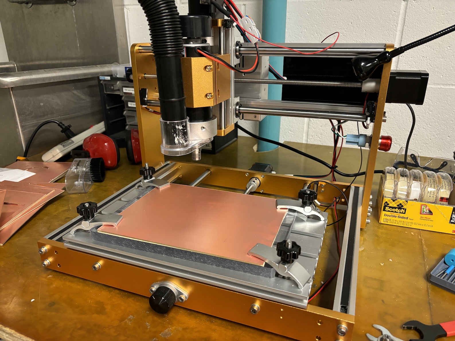
Preparing for milling
Video of running the milling machine
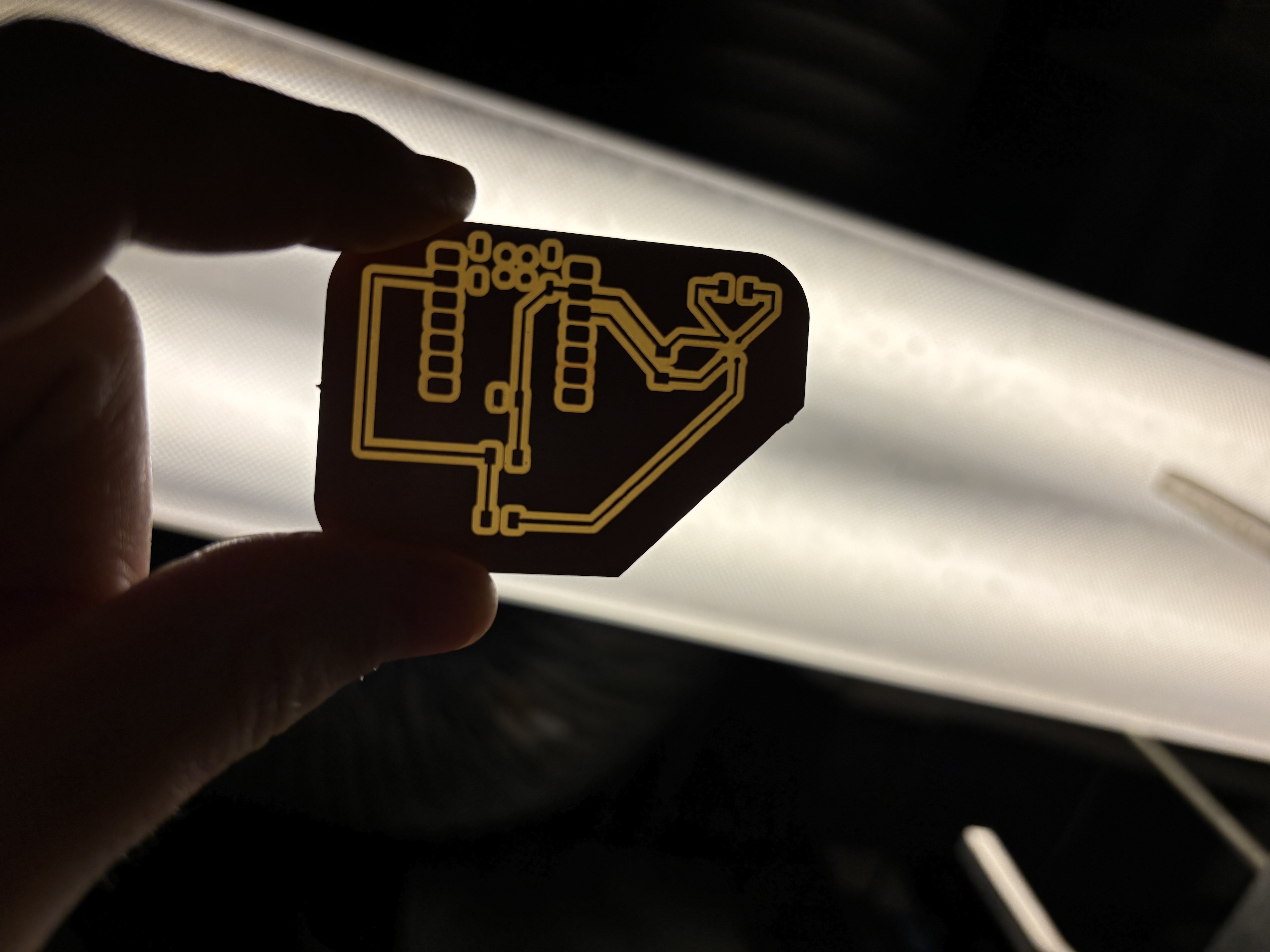
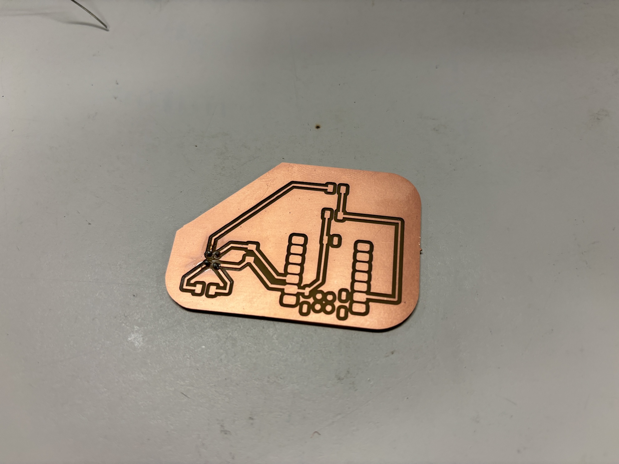
The final board
Soldering components to the board
This gets tricky! I needed to find a way to solder the tiny microphone to the board without solder paste - we don't have any in the cba shop. The microphone has 4 small pads on its underside, making it the first of its kind for me. Quentin's advice was to pre-tin the pads and then use a hot air gun, which I did.
I used the following components for my board:
- RP2040 microncontroller
- SPU0414HR5H-SB-7 link to data sheet
- Two 0.1 uF capacitors
- One 10 uF capacitor
- One 1,000 ohm resistor
I then patiently and deliberately soldered the components to the board with the help of flux. The soldering job is not good, but it's an improvement from week 06. I continued to watch YouTube videos on the basics of soldering, particularly for the microphone.
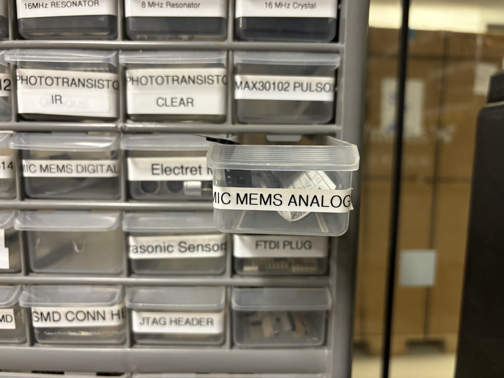
Microphone inventory in cba shop
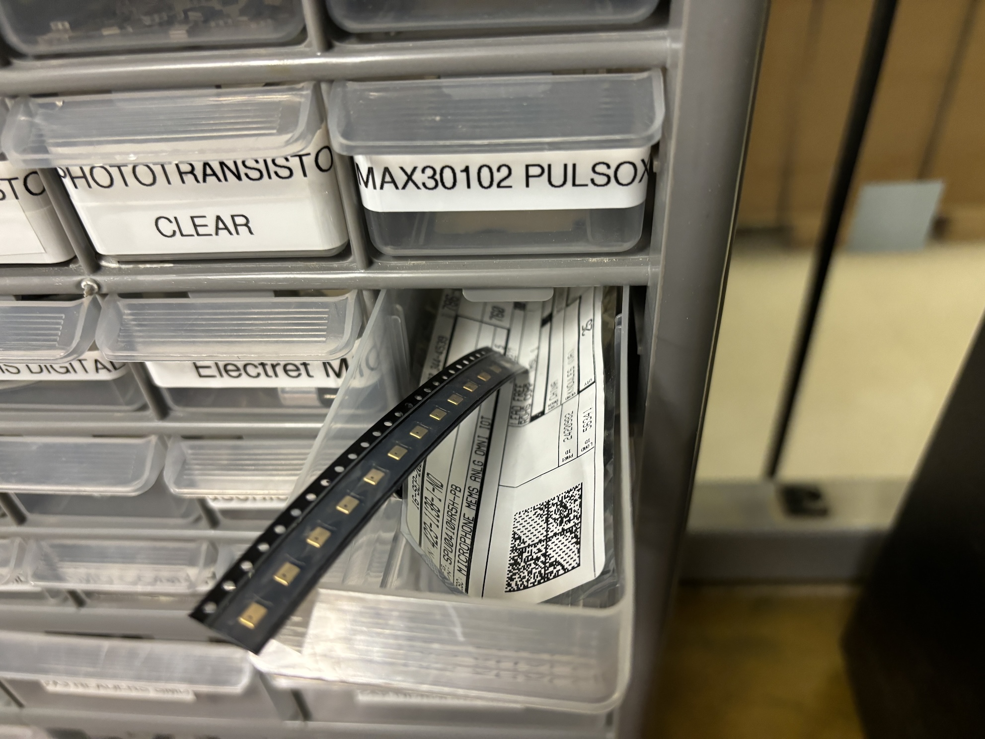
Capacitor inventory in cba shop
All the components for my board
Pre-tinning the pads for the microphone
Video of trying to solder a capacitor to the board
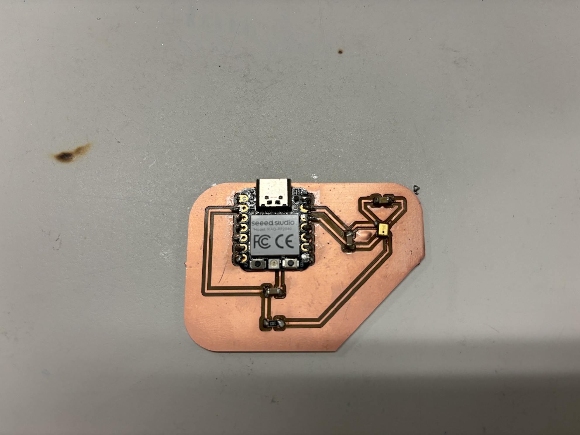
The final, ugly board
Reading the microphone
I have limited to no experience with programming, so I started with the basics. I am still trying to learn how to record sound in audio files from the microphone. For this week, I just wanted to confirm that I setup the microphone correctly, and I could see sound outputs from the analog microphone.
First I setup Arduino with my board and Xiao RP2040 microcontroller. I followed the process I documented in Week 03 Embedded Programming so I could write and upload a program to the RP2040 board. Specifically, I did the following:
- Plug in RP2040 to laptop via USB-C cable
- All the LEDs turn on, including the large one at the base of the device which blinks and changes colors
- I pressed and held the “B” button, then pressed and released the “R” button. This turned off the light, and then the RP2040 appeared as an external drive with the name “RPI-RP2”
- In Arduino IDE, I went to the Tools menu to select the right board (screenshot below).
- I wrote a simple code to read the analog value from the A1 pin. A1 is GPIO27, so pin “27” Arduino also has a tutorial on how to capture sound via the onboard analog microphone on the the Nano RP2040, a different board. link to Nano RP2040 microphone basics
- I uploaded the simple code to the Xiao microcontroller and then opened the serial plotter to check if any data was being captured. It seems to be picking up sounds!
Here is the simple Arduino program I wrote and uploaded to the board:
void setup() {
	// put your setup code here, to run once:
	Serial.begin(9600);

	}

	void loop() {
	// put your main code here, to run repeatedly:
	//analogReference(INTERNAL);
	int val = analogRead(27);

	Serial.println(val);
	delay(1);

	}
As first, the serial plotter on Arduino only displayed 50 data points along the x-axis. To see a longer time scale of the audio output, I followed Anthony’s instructors to change Arduino’s plotter window setting:
- As installed, the serial plotter for Arduino IDE 2.2 will only display fifty points at a time, insufficient for our purposes. Fortunately, as described at https://github.com/arduino/arduino-ide/issues/803#issuecomment-1338149431 at the end of https://github.com/arduino/arduino-ide/issues/803 , Arduino IDE 2.2's serial plotter is a web application written in javascript, and is easy (sort of) for you to customize and plot 500 points.
- Find the installation folder for Arduino IDE 2.2, and navigate to the subfolder "Resources/app/lib/backend/resources/arduino-serial-plotter-webapp/static/js". Make a copy of the file main.35ae02cb.chunk.js, in case something goes wrong, and then use any text editor to open the original main.35ae02cb.chunk.js file.
- Use the text editor's search function to find the text U=Object(o.useState)(50) in the file, then change the 50 to 500, save the file, and then quit the editor.
- For some operating systems, it may be necessary to change the permissions for the main.35ae02cb.chunk.js file before you will be allowed to save your changes.
- And for Mac users, you can find usually find the installation folder by searching the Application folder for Arduino IDE.app , then right clicking on it, and choosing "Show Package Contents", and opening the Contents folder.
Setting up the RP2040 board on Arduino
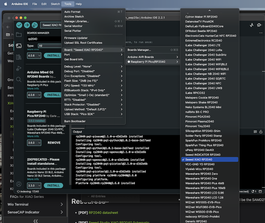
Setting up the RP2040 board on Arduino
Video of uploading the simple program to the board and viewing the outputs on the serial plotter. I snapped my fingers and made funny sounds near the microphone.