Assignment 5: Microcontroller Programming - Hello World!
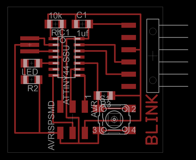
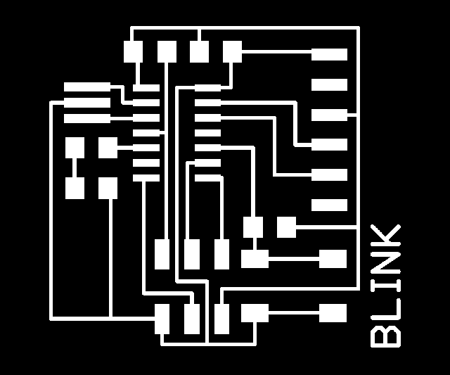
This week we were asked to program an ATtiny 44 microcontroller using a modified PCB layout from Eagle. As a first step, we were encouraged to add at least one push button and an LED to our board. Below is my modified board layout and the traces export (.png) that I used to mill the board. Here are a few things I learned along the way:
- Use at least 333ohm resistor when used in series with the LED. I decided (without doing the calculations) that a 100ohm resistor would be large enough to work in series with my LED. I never really ran into a critical error, but I was a little worried that I was drawing too much current and would either burn out my chip or my LED. I probably should have gone with the 499ohm resistor in the Fab Lab inventory (although I do like my LED's nice and bright!)
- Use at least 10kohm resistor when used in series with the push button switch. Again, this didn't cause any critical errors, but I ended up using the internal pull-up resistor inside the chip because my tiny 100ohm resistor that I stuck on my board just wasn't going to cut it.
- Leave a little more room between the push buttom and the ISP header. I was really trying to go for efficiency when laying out my board and I tried to get everything lined up and as tight as possible. But, I forgot to think that the 6-pin ISP header had a fairly large plastic connection piece which would cover up part of my switch in the current location. It's still works (especially if you don't have sausage fingers) but I could have given myself a little more room to work with.
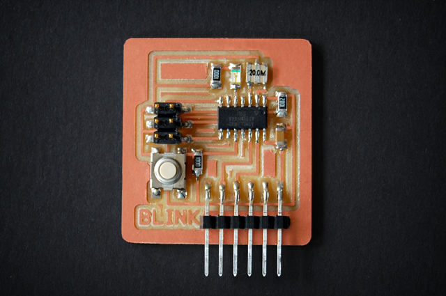
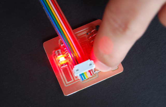
Here is the final board layour after stuffing. In general, I think everything went pretty smoothly (no major errors) but I did run into one problem when soldering on the 20Mhz resonator. Because it is so close to the microcontroller, I thought it might be a good idea to lay down a little solder on each of the three pads near the chip, then reheat them when I put the resonator on... only to realize that I had no way to rehead them all simultaneously and thus the resonator came out a little crooked. Nothing disastrous though and it all worked out in the end (check out the snazzy red led glow in the bottom image).
It definitely took me a little while to get used to programming the micocontroller using cygwin and C. The first step was just trying to get the code compiled correctly in order to make the LED light up when I pushed the button. The C code for this was very basic, but we (all of the Windows users) ran into problems when we used the Make File command. Lucikly, we had Natalie in our class who suggested we use the following command:
- export TEMP=/tmp
- Then try retyping the Make File command
As I understand it, Windows users have to type in the export TEMP command everytime they launch a running instance of cygwin. You only need to do it once, and you don't have to cd to any directory to do it... but you have to do it in order to use the Make File command. From that point on, it was smooth sailing (Thanks again Natalie).
So, I decided to take the blinking LED example one step further and decided to write a little program that would spell out "Hello World!" in morse code when you push the button (I know... it's ground breaking stuff). Below is a quick video of it in action (sorry, the video quality is really crappy... my camera wouldn't seem to focus on one single point when it started blinking). The code is attached below in case anyone ever wants to use it again.
LED_Hello code:
//LED-switch program
#include <avr/io.h>
//#define F_CPU 1e6
//CPU clock speed
#include <avr/delay.h>
#define TRUE 1
#define FALSE 0
#define SHORT 100
#define LONG 300
#define LEDPIN PB2
int main() {
//setup
//PA3 = Switch
//PB2 = LED
PORTA = _BV(PA3);
//Turn Button pullup resistor on
DDRB = _BV(LEDPIN);
//Enable output on the LED pin
//loop
while(TRUE) {
//button controller
if (PINA & _BV(PA3)) //button has not been pushed
{
PORTB = 0; //turn off
}
else
{
_writeH();
_writeE();
_writeL();
_writeL();
_writeO();
_delay_ms(LONG);
_writeW();
_writeO();
_writeR();
_writeL();
_writeD();
_delay_ms(1000);
}
}
}
void _writeH(){
//Write "H" represented by " · · · · "
PORTB = _BV(LEDPIN); //turn on
_delay_ms(SHORT);
PORTB = 0; //turn off
_delay_ms(SHORT);
PORTB = _BV(LEDPIN); //turn on
_delay_ms(SHORT);
PORTB = 0; //turn off
_delay_ms(SHORT);
PORTB = _BV(LEDPIN); //turn on
_delay_ms(SHORT);
PORTB = 0; //turn off
_delay_ms(SHORT);
PORTB = _BV(LEDPIN); //turn on
_delay_ms(SHORT);
PORTB = 0; //turn off
_delay_ms(LONG);
}
void _writeE(){
//Write "E" represented by " · "
PORTB = _BV(LEDPIN); //turn on
_delay_ms(SHORT);
PORTB = 0; //turn off
_delay_ms(LONG);
}
void _writeL(){
//Write "L" represented by " · — · · "
PORTB = _BV(LEDPIN); //turn on
_delay_ms(SHORT);
PORTB = 0; //turn off
_delay_ms(SHORT);
PORTB = _BV(LEDPIN); //turn on
_delay_ms(LONG);
PORTB = 0; //turn off
_delay_ms(SHORT);
PORTB = _BV(LEDPIN); //turn on
_delay_ms(SHORT);
PORTB = 0; //turn off
_delay_ms(SHORT);
PORTB = _BV(LEDPIN); //turn on
_delay_ms(SHORT);
PORTB = 0; //turn off
_delay_ms(LONG);
}
void _writeO(){
//Write "O" represented by " — — — "
PORTB = _BV(LEDPIN); //turn on
_delay_ms(LONG);
PORTB = 0; //turn off
_delay_ms(SHORT);
PORTB = _BV(LEDPIN); //turn on
_delay_ms(LONG);
PORTB = 0; //turn off
_delay_ms(SHORT);
PORTB = _BV(LEDPIN); //turn on
_delay_ms(LONG);
PORTB = 0; //turn off
_delay_ms(LONG);
}
void _writeW(){
//Write "W" represented by " · — — "
PORTB = _BV(LEDPIN); //turn on
_delay_ms(SHORT);
PORTB = 0; //turn off
_delay_ms(SHORT);
PORTB = _BV(LEDPIN); //turn on
_delay_ms(LONG);
PORTB = 0; //turn off
_delay_ms(SHORT);
PORTB = _BV(LEDPIN); //turn on
_delay_ms(LONG);
PORTB = 0; //turn off
_delay_ms(LONG);
}
void _writeR(){
//Write "R" represented by " · — · "
PORTB = _BV(LEDPIN); //turn on
_delay_ms(SHORT);
PORTB = 0; //turn off
_delay_ms(SHORT);
PORTB = _BV(LEDPIN); //turn on
_delay_ms(LONG);
PORTB = 0; //turn off
_delay_ms(SHORT);
PORTB = _BV(LEDPIN); //turn on
_delay_ms(SHORT);
PORTB = 0; //turn off
_delay_ms(LONG);
}
void _writeD(){
//Write "D" represented by " — · · "
PORTB = _BV(LEDPIN); //turn on
_delay_ms(LONG);
PORTB = 0; //turn off
_delay_ms(SHORT);
PORTB = _BV(LEDPIN); //turn on
_delay_ms(SHORT);
PORTB = 0; //turn off
_delay_ms(SHORT);
PORTB = _BV(LEDPIN); //turn on
_delay_ms(SHORT);
PORTB = 0; //turn off
_delay_ms(LONG);
}
Make File code:
PROJECT=led_hello
SOURCES=$(PROJECT).c
MMCU=attiny44
F_CPU = 1000000
CFLAGS=-mmcu=$(MMCU) -Wall -Os -DF_CPU=$(F_CPU)
$(PROJECT).hex:$(PROJECT).out
avr-objcopy -j .text -O ihex $(PROJECT).out $(PROJECT).c.hex;\
avr-size --mcu=$(MMCU) --format=avr $(PROJECT).out
$(PROJECT).out: $(SOURCES)
avr-gcc $(CFLAGS) -I./ -o $(PROJECT).out $(SOURCES)
program: $(PROJECT).hex
avrdude -p t44 -c usbtiny -U flash:w:$(PROJECT).c.hex
program-dasa: $(PROJECT).hex
avrdude -p t44 -P /dev/ttyUSB0 -c dasa -U flash:w:$(PROJECT).c.hex
program-avrisp2: $(PROJECT).hex
avrdude -p t44 -P usb -c avrisp2 -U flash:w:$(PROJECT).c.hex
program-avrisp2-fuses: $(PROJECT).hex
avrdude -p t44 -P usb -c avrisp2 -U lfuse:w:0x7E:m
program-dragon: $(PROJECT).hex
avrdude -p t44 -P usb -c dragon_isp -U flash:w:$(PROJECT).c.hex