Assignment 6: 3D Scanning and Printing
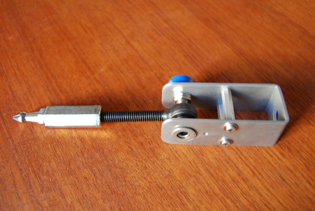
This week's assignment was to 3D scan and print an object (not necessarily the same one). I had a little trouble documenting the process (particularly because I still haven't picked up my 3d print) so I'll start with the 3D scanning process. My main goal for this assignment was to actually build a 5-axis digitizing arm (as part of my final assignment)... but I didn't quite get it finished in just one week (see more information about the final project below). I decided to scan one of the legs of the mechanical arm (this is the hand of the arm). I decided to put the Z-corp ZScanner 700 through its paces just to see how accurate it could get on a part like this.
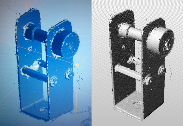
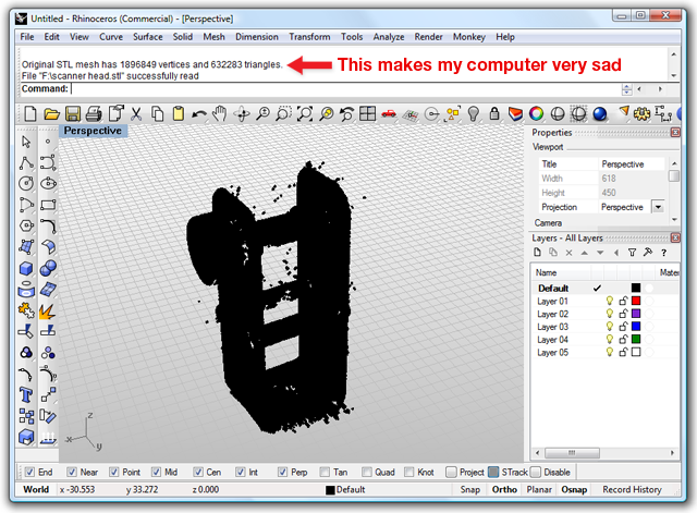
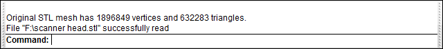
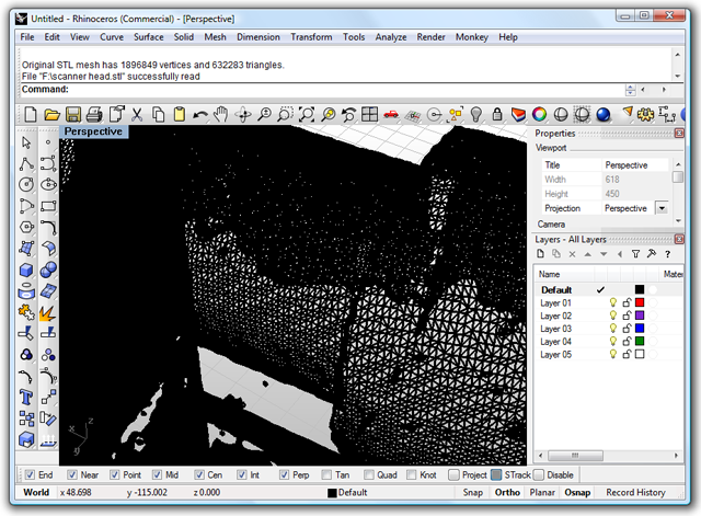
The nice thing about this type of scanner is that you can scan "in-the-round" which was really interesting to see in the demo. However, because of the size of the piece, I decided it might be best to use a stationary stage to scan against (see video below). The scanning process with this machine is fairly seemless and it didn't take long to get a relatively good mesh - although there are some distinct limitations. First, as you can see by the images below, it's almost impossible to create a water tight mesh using this process. It may be possible to clean up the mesh (and perhaps close some of the gaps) using Geomagic, but I didn't get a chance to do that. The images side-by-side comparison image below is the final mesh from the Z-corp software and the imported STL file in Rhino. This mesh has been run through three scan iterations, each time decreasing the bounding box and increasing the resolution. You can see that it's difficult to get clean results on the underside of protruding objects (unless you're scanning in the round... which I didn't do for this object). The Z-corp website says the 700 series scanner has an accuracy of 50 microns which plausible... although I found it very difficult for the scanner to pick up the fine details on corners and crevices. The mesh is still pretty detailed though. In fact, I might even say it's too detailed because the STL file that I imported into Rhino was very heavy. The mesh had almost 2 million vertices and over 600,000 triangular faces (which isn't actually too bad all things considered... I've dealt with many more polygons when doing high-resolution renderings) but it still made my computer lag behind quite a bit. In closing, the scanning process was actually quite fun and the tangible interface for the scanner was very interesting to use. However, given the mesh limitations and the inability to create closed meshes, I'm not exactly sure why I would ever choose to use this type of 3D scanner again.
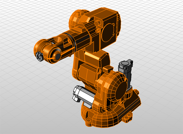
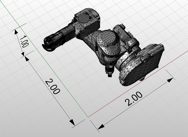
As I mentioned earlier, this week's 3D printing assignment was a little bit difficult to document because the print was sent out Friday night (or Sat. morning) and I hadn't had a chance to pick it up and clean off the support material. My final project proposal is to create a 5-axis digitizing arm which can track point data (for scanning) and simultaneously send that data to the ABB-IRB 140 Robot to CNC mill a duplicate copy of the scan. There is more information about this process below, but for now, suffice it to say that I decided to 3D print a miniature replica of the ABB 5-axis robot. I didn't actually model this object, but it can be downloaded from the ABB website. The scaled STL model is roughly 2"x2"x1" is approximately 6.4mb. Once I pick up the final print, I will add more documentation about the finishing process.
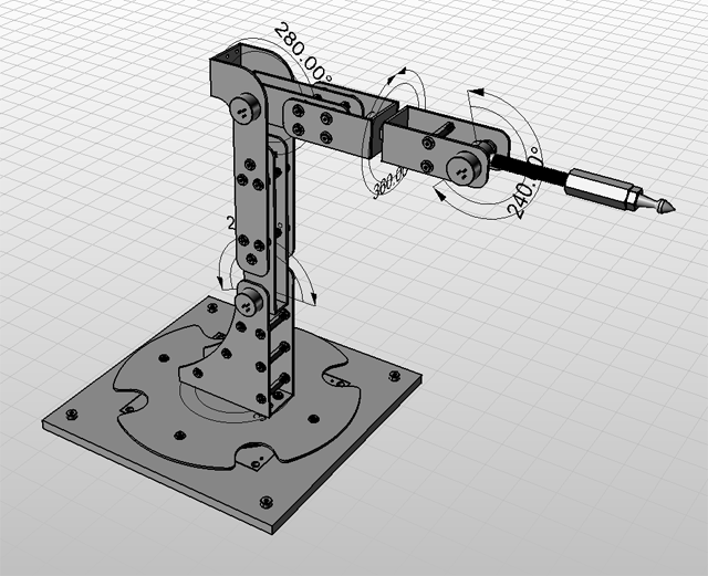
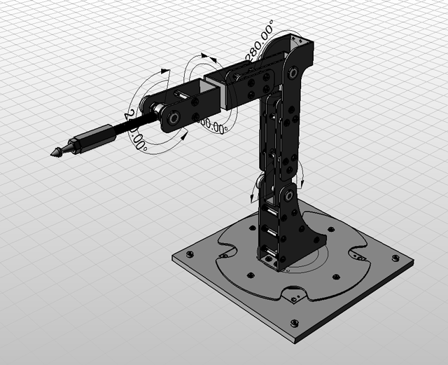
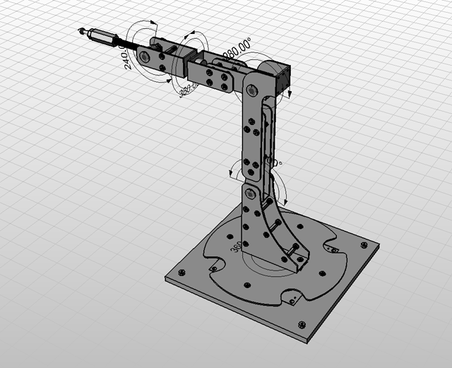
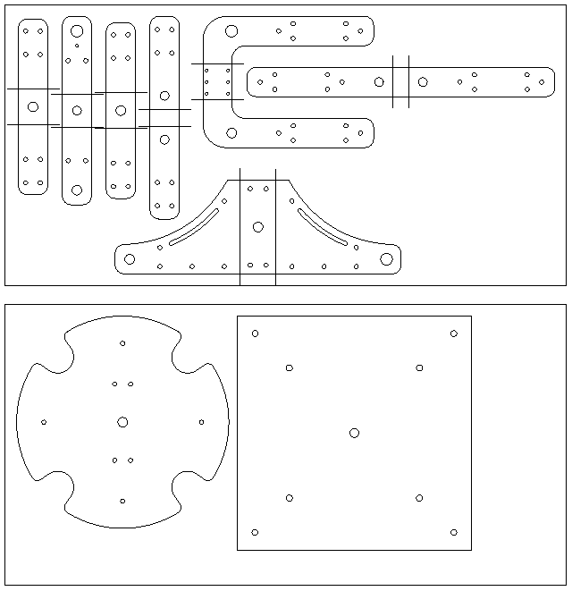
Now, my original goal for this week's assignment had been to build a fully functional 5-axis digitizing arm (similar to a microscribe). The project can roughly be summed up in 2 phases: 1) build a 5-axis digitizing arm using the same proportions as the ABB-IRB 140 robot and 2) stream the scanning point data to the 5-axis robot using RAPID code so that you can simultaneously CNC mill a duplicate copy of the scanned object.
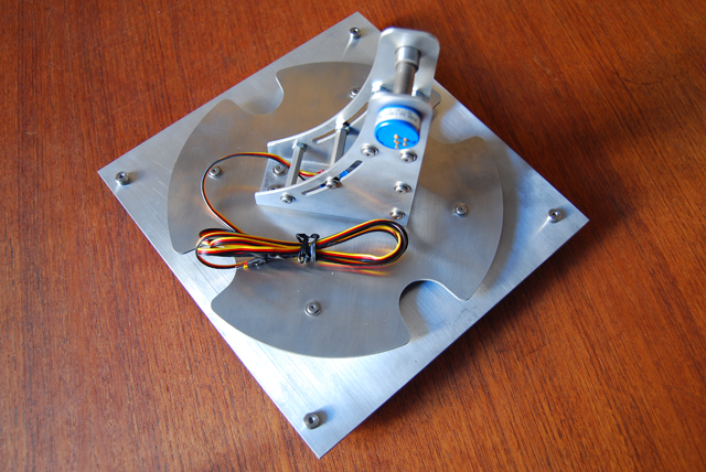
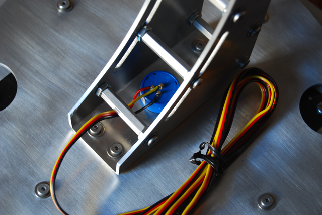
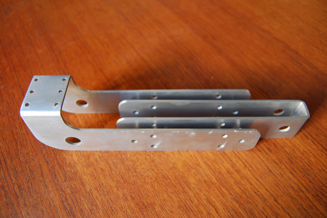
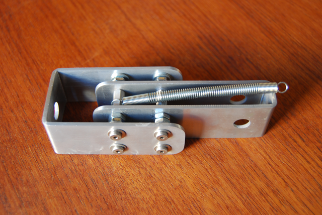
The 5-axis digitizing arm starts by mapping out the pivot points of the ABB robot (making sure to use the data sheet to check the angle limitations of each pivot. I decided to use high precision potentiometers from Bournes to measure the angle between each leg of the arm (as well as acting as the hinge). Once the arm is assembled, each potentiometer will be streamed to into Grasshopper (via Firefly) to create a forward kinematic model of the mechanical arm. Knowing the length of each arm and the rotation of each hinge, it will be quite easy to track the end of the digitizing arm, creating a mesh point cloud for 3D scanning. Using two digital sensors (I haven't decided on whether this will be a foot pedals or push buttons) I can record or reset the point data. From there, it's just a matter of converting the point data to RAPID code (since I can track the exact time of each recording and the position data, I can determine the velocity of the robot at any given time to match the exact speed of the digitizing arm).
I decided to change the bearings that I was using for the hinges, so I have to wait for the parts to come in from McMaster Carr before finishing the arm. This should be finished this week, so ideally I should have the forward kinematic model up and working by next week. Below are some progress shots of the development of the 5-axis arm.