Assignment 9: Shape Memory Alloy Panel System (Output Devices)
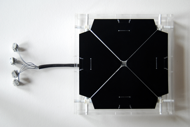
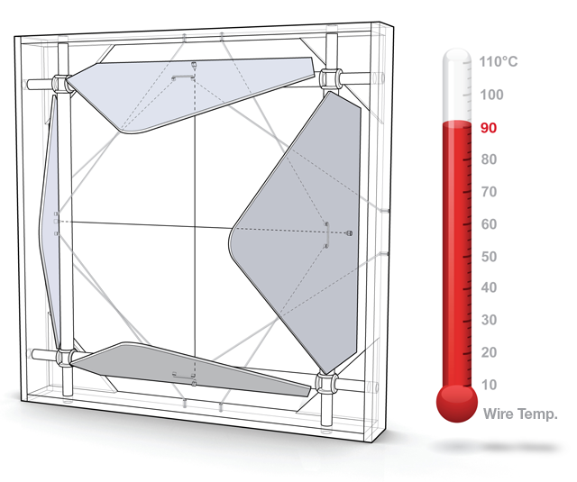
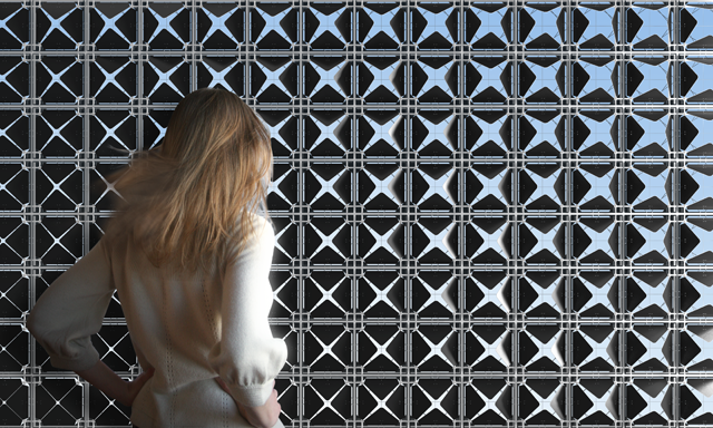
For this week's assignment I decided to revisit an older project, but approach it from a slightly different way now that I have more knowledge about custom circuits and output devices. I had done work two years ago with Shape Memory Alloy wires (Flexinol) to develop a heat sensitive facade system that was entirely energy independent. I was able to achieve fairly remarkable results by using custom calibrated SMA wires that would enter their hysteresis transformation near room temperature. Essentially, the SMA wire acts as the sensor, processing device, and actuator all-in-one. While this device is specifically calibrated for heat, you could send current through each wire and connect it to a custom PCB and have it respond to nearly any type of sensor as well. So, I've come full circle with this design - redesigning the system to use a push button switch to open and close the panels.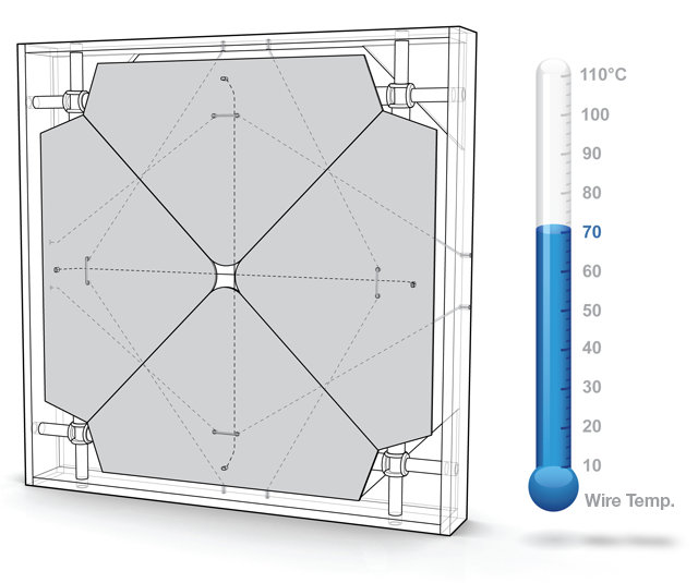
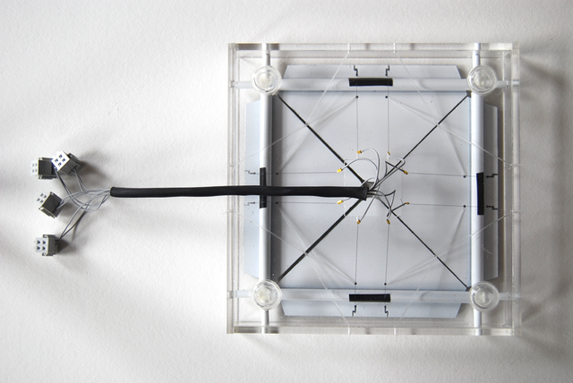
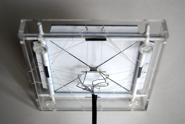
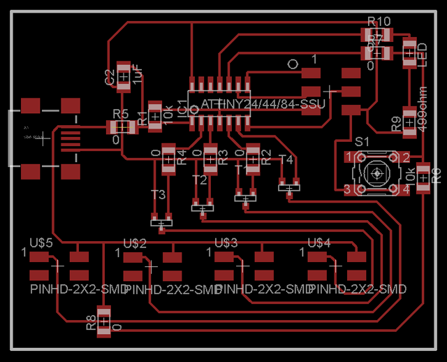
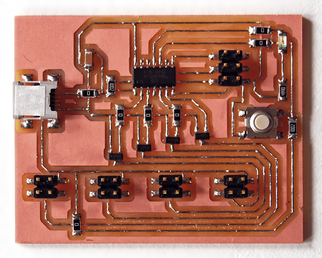
For the design to work properly, I had to design a custom PCB from scratch. After sitting down with David Mellis (who was a big help this week) I learned thatI needed to have four n-channel MOSFETS (one for each wire) in my design. Essentially, each wire needs roughly 400mA of current and 5V of power to generate enough heat to get the wire to enter into its contraction cycle (you could probably get away with less, but this is the theoretical values from the calculations). So, I decided to use a USB connector for power but I needed a way to send 400mA because the max output from a single pin on the microcontroller is only 40mA. There are four pins on the microcontroller which trigger the MOSFET to send the full power and current from the USB power source through each wire. Since, I couldn't send 400mA of current through each wire at the exact same time (exceeding the limit from my USB power source), I had to turn them on one at a time (in the C-code). In order to achieve the effect of having all 4 wires contract at the exact same time, I decided to send very brief pulses through the wires (roughly 100ms) and cycle through each of the four wires. The on board LED was very helpful for debugging purposes (I would highly recommend putting them on every board).
I built the panel system from scratch over the weekend and I think it all worked really well (the design has been modified from previous versions) but there were some minor things I would change. I wish I had sanded all four of the inner rods (about which each panel rotates) because one of them was a little tight and thus it tends not to open quite as much. I also expected the panels to have a wider open position. I would probably modify the next iteration slightly so that the SMA connection was slightly closer to the pivot arm, enabling greater lever action and hopefully great range of rotation. I think scaling up the prototype to twice this scale could also help in this regard. Below is a video of the panel system in action.