Output Devices
The assignment of this week was to use an output device to do something through a microcontroller. Unfortunatelly I didn't manage to succesfully make mine do what I would like it to do =[: I burnt a board, broke an endmill, and spent a lot of time trying to find a good layout without too many vias. I wanted to work with motors as an output device, and being undecicive choosing between stepper or DC motor, I spent unproductively my time lingering between those two options. My first idea was to build a light following robot. My second idea was to combine the hello.stepper example with the hello.ftdi to control a sliding head/gantry with the keybord using a stepper motor. None of those two was finished.
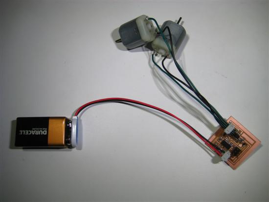
Hello.H-bridge.44
I started with Neil's hello.hbridge to get familiar with controlling dc motors. It took a while to understand how an h-bridge works and how the c code controls it, but at the end I got a basic understanding of it. Here is what I did:
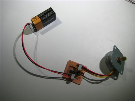
Hello.Stepper.44
Next, made the hello.stepper example to understand how to move a stepper motor. Although the theory is easy to grasp, the code was not so clear to me. I manage however to tweak the code to do other meaningful things such as changing the speed/direction of the rotor.
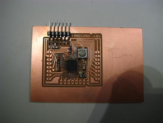
Fabduino
Next, I decided to make a Fabduino, following Ed Baafi's instructions. I wanted to have a custom made cheap arduino-compatible board as an emergency plan in case all other things don't work. We bootloaded it with Ed and it works nicely!
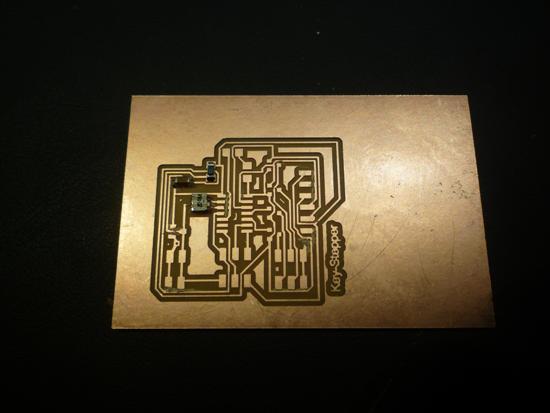
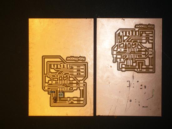
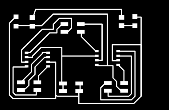
Keystepper
Next, I decided to combine the FTDI example witht the stepper example to make a stepper mode that I could control with my keybord. I think my schematic is good, but I couldn't find any layout without overlaping nets/traces, so I had to make vias. Unfortunaltelly I wasn't careful with my tolerances and as a result
.png)
LightBot
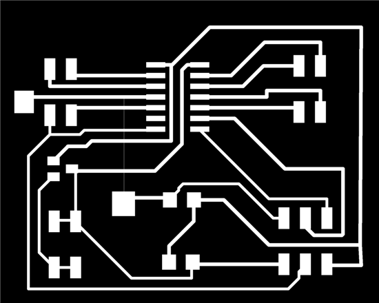
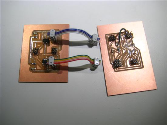
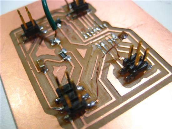
Finally, I tried to make the light-following robot. I combined my previous design for the Optical Encoder that ises two photo transistors with two H-bridges. It was impossible to avoid crossing traces, so instead of using vias I decided to brake to board into two boards and connect them with ribbon cables. Sowhere in the process I screwed up with my schematic cause my photodiodes don't give any input in my microcontroller! Moreover, when I finished the board I hooked up the power in the wrong way and I burnt my voltage regulator and most probably my tiny44 too, cause the entire board was smoking and smelling. Phew! Moreover, during desoldering of the tiny44 I pulled up the copper traces destroying my board. Here is my schematic and my two boards witht the tiny55 missing after desoldering it.
Disaster
Next Steps
For the next steps I will complete the light following robot project and get back to update this page. Stay tuned.