My project for this week:
The assignment of this week was to 3D scan something, and then 3D print something. For the 3D scanning, I decided to experiment with various techniques & machines: I used the Minolta VIVID 910 3D scanner, the NextEngine 3D scanner, and the Structured Ligh method using a digital camera and a projector. For the 3D printing I decided to model and print a set of 4 Sake cups for my home.
3D Scanning
I realized that most 3D scanning techniques that are based on light (either normal light or laser) are doing more or less the same thing. They consist of two components: a camera and a light projector that projects a pattern on the surface to be scanned. The camera records the projected pattern (typically is one or more stripes or a checker board pattern), and then a point cloud (a collection of 3D points) is generated by calculating the distortion of the pattern. A 3D scanner can be extremely expensive equipment and when you consider that you can basically do the same process in-house using just a projector and a camera you tend to deslike it. A very effective, low-cost, and cool to do method is the milkscanner (check it out here). A common pitfall of all 3D scanning methods is that they cannot scan cavities.
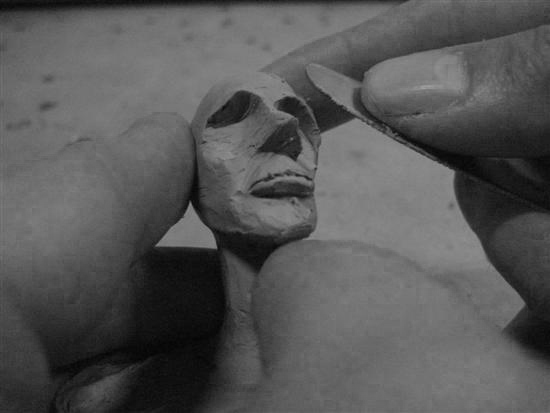
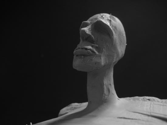
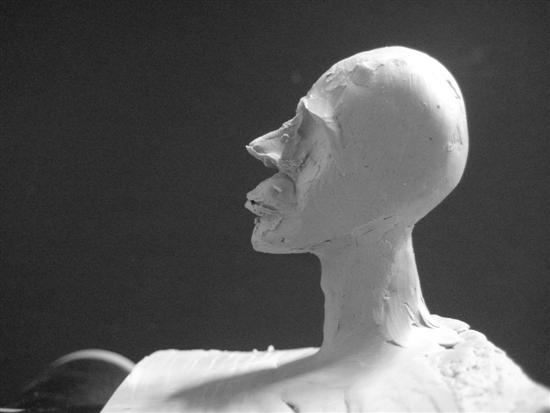
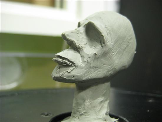
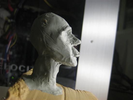
Building the physical model from plasteline
I used plasteline to mold a caricature head. I like plasteline because it gives a smooth surface. Unfortunatelly I couldn't find more plasteline to make my model bigger.
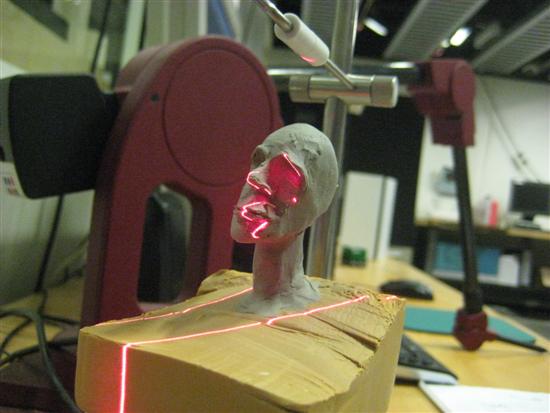
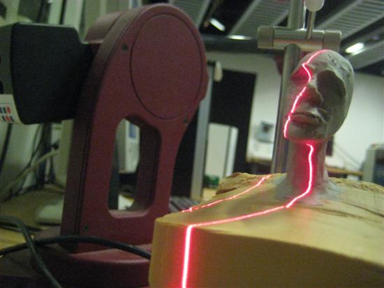
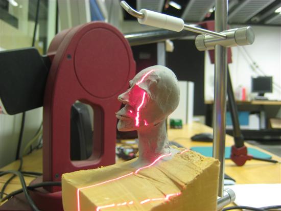
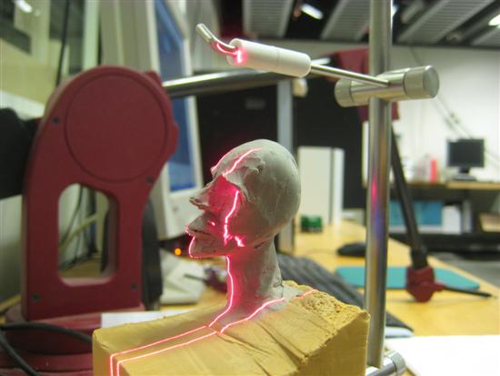
Scanning the physical model in Minolta VIVID 910
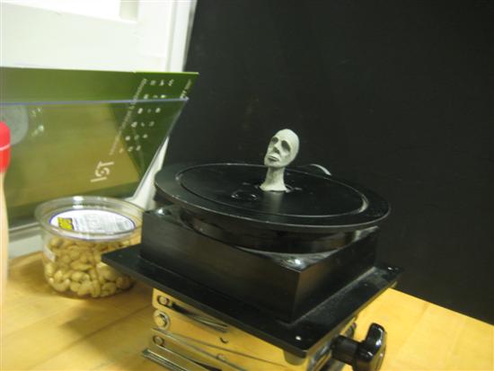
First you put your model on the turntable. Next you perform consecutive scans by rotating the table. I did 8 scans, each with 45 degrees difference in angle. Before performing the scans you must first calibrate the scanner to let the software know where the pivot axis is. This will be needed later when the software combines the rotated scans into one single file.
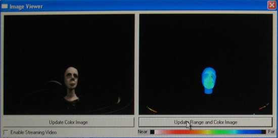
After calibrating the scanner you need to adjust the depth field of focus. For some reasons autofocus in the VIVID910 did not work so well so I had to manually set it. It seems that the minimum focal distance is 500mm so with the 14mm lens you cannot get closer than that. This obviously has an impact on the scannin resolution which is basically the reason of why my scan is not so detailed relatively to its size. To adjust the depth of field you can change either the laser intensity or the focal distance. You mant to make sure that the depth of your object (its length along the focal axis) fits in most of the color range (from red to blue) that you see bellow. In my case, my model fitted only in the green/blue area. I could have gotten a better range if I placed my model even further away from the lense but that would also decrease the accuracy of my scan.
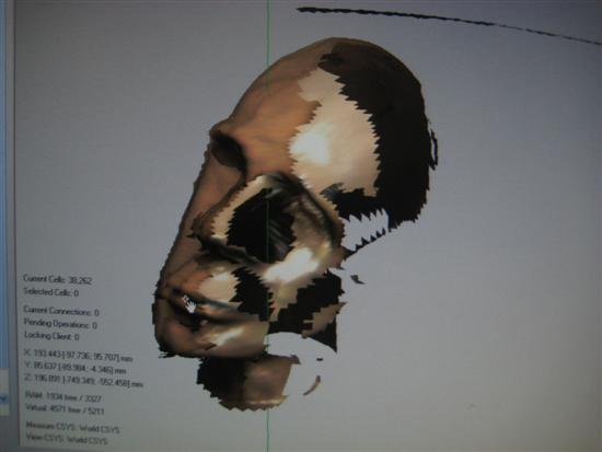
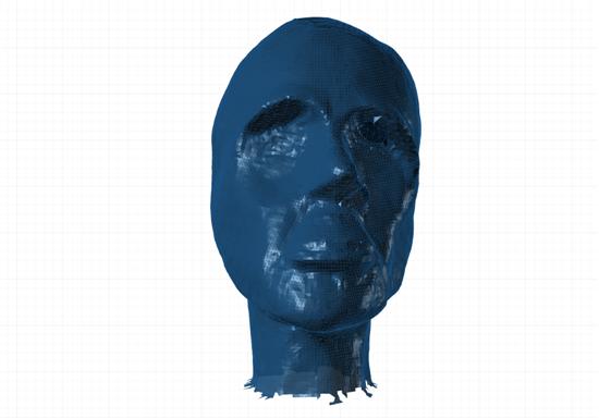
Bellow is the first of the 8 scans. When all scans are performed (360 degrees in total) the software stitches them together into one single file and fills the holes.
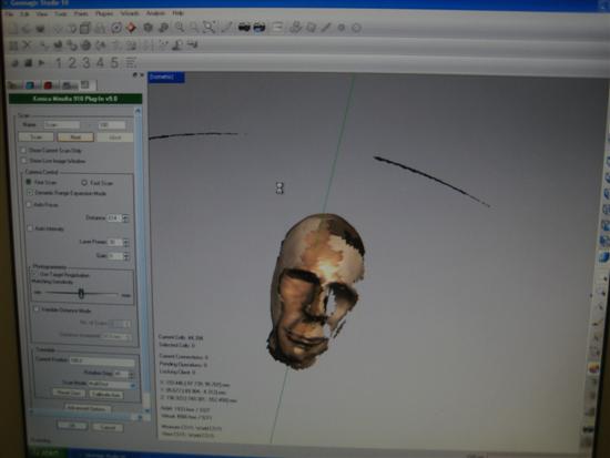
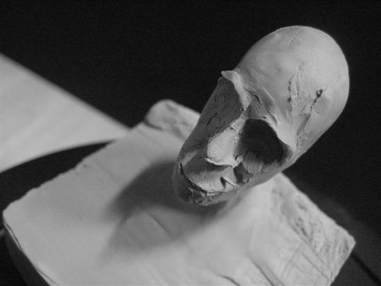
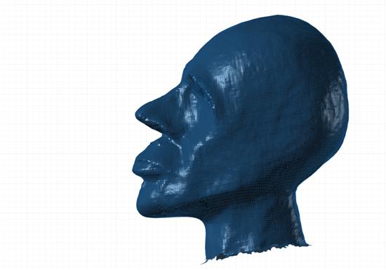
Bellow is the result of my scan once all 8 scans and stitching were performed. Since my model did not have too many deep convex surfaces I did not have many holes. The holes are created by the shadows that the laser casts on the model's surface, in exactly the same manner that a lamp light would do if obstacles were shadowing its source. I only had one shadow hole in the bottom part of the chin and in one of the two eye cavities.
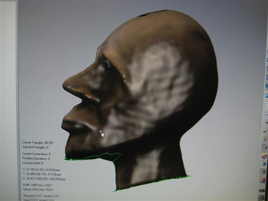
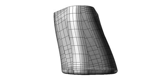
Bellow is the resulted stereolithography (.stl) file.
Next, I tried the NextEngine scanner. The process was very similar. The difference is that VIVID910 performs horizontal scans while NextEngine performs vertical scans. NextEngine is supposed to work better in smaller objects. My results were also very similar.
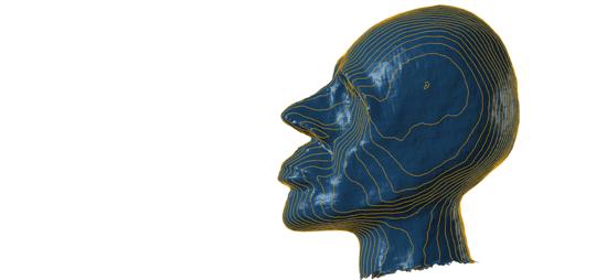
Structured Light
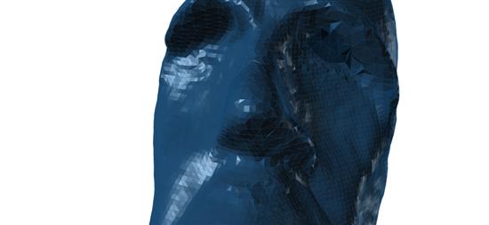
I also experimented with Structured Light method. Structured Light is a similar method to laser scanning but much cheaper (Thanks David!). It consists of a digital camera and a projector that projects patterns of horizontal and/or vertical stripe that change in time. The camera then records the deformations of the stripes and an image procesing algorithm translates this distortion into XYZ coordinates. David Lakatos gave a nice tutorial and provided the links for the processing code and libraries that do Structured Light. You can find the code here, and the libraries here and here (thanks Jie!).
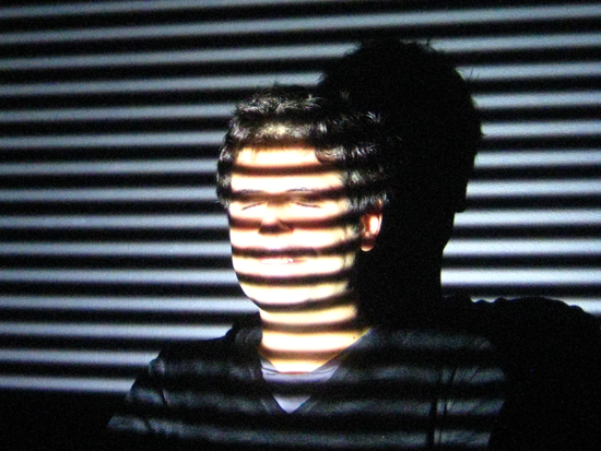
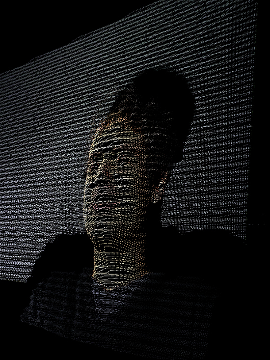
The result is not incredibly accurate but I did only one scan since there was no way of guarantiing that my relative position to a pivot axis would not change during rotation. If I could perform scans for the entire 360 degrees I would have been able to scan my entire head.
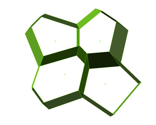
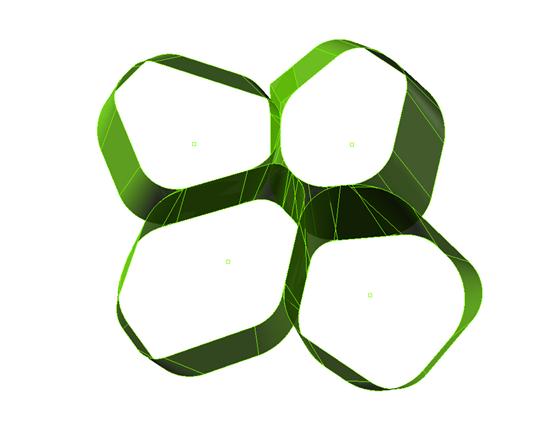
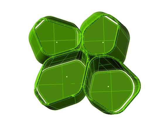
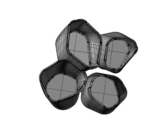
3D Printing Sake cups
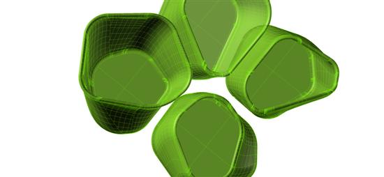
I designed the cups starting from a spatial voronoi diagram, which I then used to make the cup prisms.