DearGear: How to make a 4WD toy car with 3 differentials
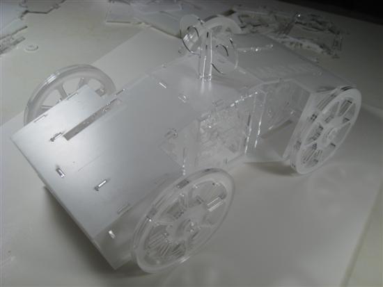
My project for this week: DearGear: a complex toy-car entirely made in lasercutter and manually assembled with snap fit flexure joints (no glue used!). DearGear uses 3 differentials to unevenly distribute torque (applied from top) to each of the four wheels. The design consists of 234 parts.
The assignment of this week was to make a press-fit construction kit using the lasercutter or vinlylcutter. Since I already had some experience in lasercutting I decided to give myself a challenge and make a rather complex mechanism or mechanical linkage using planar parts. One of the design challenges when dealing with press-fit assemblies using 3-axis cnc machines is to make sure that all your connections are perpendicular. This is because the machine cannot cut beveled edges. Another challenge is to ensure that parts won't fall apart after the assembly. This can either be achieved by using tight tolerences or by devising snap-fit flexure joints. This means that a press-fit project with kinetic linkages creates the design challenge of both ensuring tight connections at the fixed parts while keeping rotating parts loose enough to mitigate undesired friction.
Inspiration
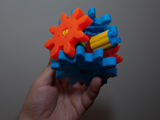
Last summer, while I was playing with a construction kit toy I got for my nephew as a present, I used four gears to make a mechanism similar to a differential. This was the inspiration for this project.
I then found this amazing video explaining the fundamentals of the differential, so I decided to make a 4WD car that uses differential gears for distributing torque to the wheels. A central axis will transmit through the first differential the torgue to the front and rear wheels while 2 more differentials will transmit the toque to each wheel individually.
Process
I developed a Rhino model of the differential mechanism and made some kinematic studies in Grasshopper. I found this neat plug-in for Rhino that automatically makes gears for you, so I decided to do something with it.
.jpg)
Making gears using GearGen and moving them using Grasshopper
.jpg)
This is the first model of the differential mechanism.
.jpg)
Next, I connected 3 differentials together: the middle one transmits torque to the other two.
.jpg)
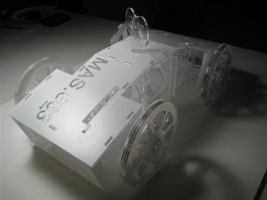
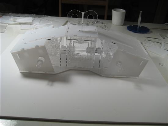
Final design of the car
![]()
Transmission mechanism
.jpg)
Image rendering using V-Ray for Rhino
.jpg)
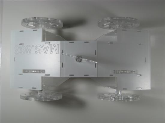
Top view
.jpg)
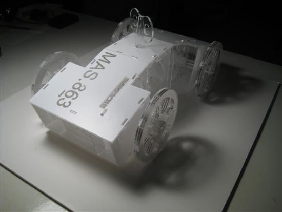
Side view
.jpg)
Front view
.jpg)
234 parts for lasercutting
First Tests
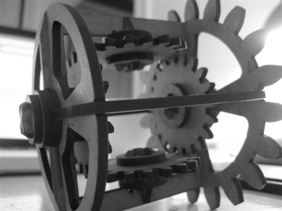
This is the first prototype of the differential. I made it using 3mm masonite boards. Friction is an issue. It would be interesting to lasercut a ball (or disk in this case) bearing ring out of masonite to mitigate friction.
Joint Design
Press-fit construction kit means that parts are interlocked and kept together without glue or any other sort of adhesive. For materials with relatively high friction coefficients and/or low hardness such as wood friction can do this job; if the tolerances are designed such that parts get really tight connections then this can be enough to make your structure hold firm. However friction itself is not always good. First of all it takes the same force to install and uninstall parts together which is not always desired. Second and most important connection forces (friction) change if materials change size due to thermal expansion or contraction. In some cases you put together a kit in the morning to find it torn apart in the night because moisture changed proportions and sizes of the parts. Finally, a third issue is that friction cannot work for hard and smooth materials such as plexiglass.
Flexure Joints
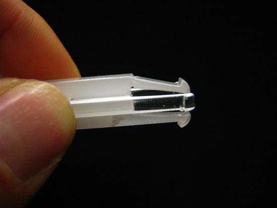
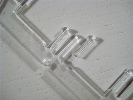
A more sophisticated approach is to design snap-fit flexure joints that bend and trap geometrically the parts together preventing them from dissasembling similar to how your seatbelt fasts. In this project I worked with flexure joints to achieve firm connections between the plexiglass parts. Designing a good flexure joint is difficult because you need prevent braking from too much bending.
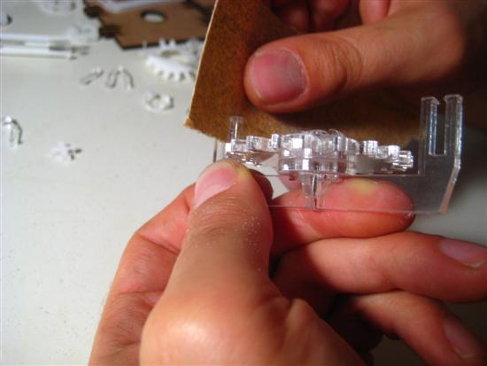
The first attempts failed because the material was too thick causing the flexures to brake apart. The second version was more refined leaving more lenght and less thickness for the flexures to bend suficiently.
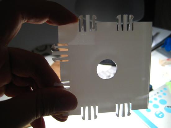
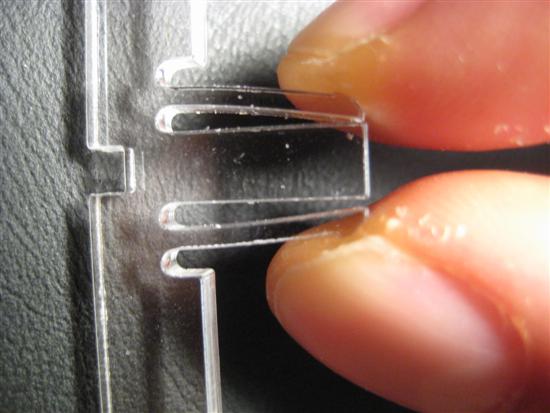
.jpg)
The initial (top) and the updated (bottom) flexure joint. Flexure length is increased, material is thinner and trapping teeth added to lock the parts together.
From my assembling experience I came to the conclusion that having too many flexure joints at each edge is not good: assembly process takes more time, becomes more difficult, and it is easier to brake parts. Instead I would say that an average of only two flexures with trapping teeth at oposite cornes of each edge would be sufficient to prevent parts from falling apart, while giving enough flexibility to manually dissasemble the parts if/when needed.
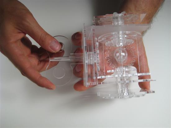
It works!
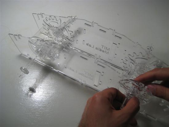
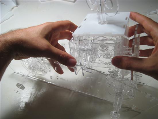
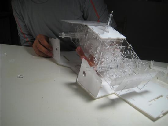
Assembly: Putting everything together
Assembly was a bit difficult. Many parts broke so I had to redesign the flexure joints. Hundreds if not thousands of a milimiter can make the difference between braking or not a part.
What worked
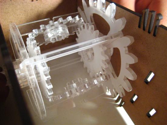
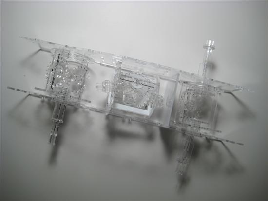
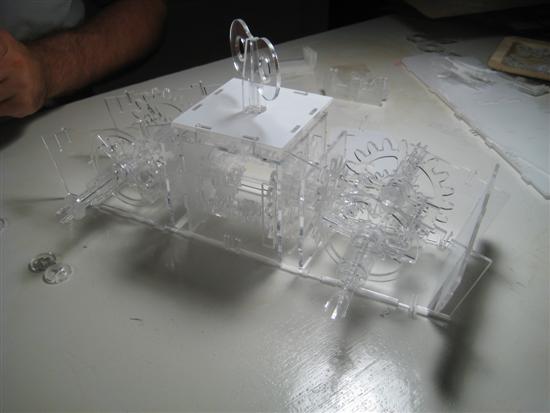
First of all the mechanism. It is fantastic to see the three lasercutted differentials work together! By applying torque to the main transmission shaft on the top, all four wheels spin; however if you block one, then torques is redistributed to the remaining three, etc. Another success was the flexure joint design. Although I still need to do refinemenets such as increasing the size of the traping heads while maintaining slenderness of the cores of the flexures. However figuring out the right number of flexure joints is particularly tricky since you have to be extra cautious of not overconstraining the assembly by designing to many flexure joints.
What didn't work
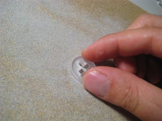
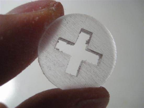
One problem was to determine the right scale during printing. Many lengths were multiples of the material thickness like for example the lenght of the wheel axels. Any tiny errors multiplied as the disks had to be stacked and as a result I could either sand the final disk to make it thiner, or redesign the wheel axel. Since I could not laser cut again I had to manually sand the disks. Another problem was that masonite and plexiglass have different properties and the same geometry can be assembled in one material but brake apart in the other. I had to go through many tests to find satisfactory dimensions.
Next steps
For next steps for this project I want to further develop the joint design, and work on steering mechanism. Finally I would be interested to do some electronics work to create a low cost 4WD RC vehicle or autonomous robot.
Videos & Links
Video 1
Video 2
Video 3