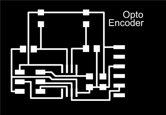
My project for this week: Optoencoder, a custom made optical encoder for precision machining applications.
The assignment of this week was to build an input device using a sensor, measure something and do some stuff with it. I decided to make an optical encoder to measure position, velocity, and direction. Optical encoders are used in closed loop precision machining systems as a way to determine current position of a robotic gantry (or head or arm) in relation to where the gantry should theoretically be.
Optical encoders work by measuring the frequency of... An advantage of optical encoders is that they are frictionless and relatively simple.
Although I managed to build the device and the hardware, I could not get my code do what I wanted it to. Building from scratch a microcontroller with sensor and measuring something is significantly difficult. The following steps are necessary: First you need to teach your microcontroller how to measure with the sensor; next you need to tell your microcontroller how to talk to your computer through a serial communication port; next you need to teach your computer how to listen the microcontroller and get the data from the serial communication port; finally, you need to tell your computer what to do with the data. The problem is that the programming language that the microcontroller understands will most probably be different than the programming language you will use to program your computer, so you end up (as usually) dealing with different syntax and commands.
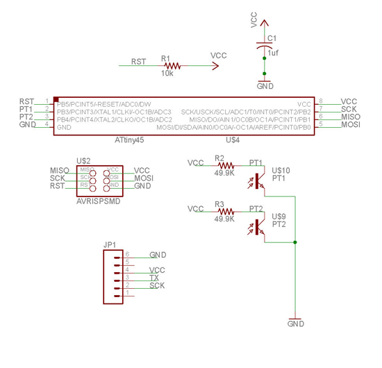
I used two sensors (photo transistors) for my encoder so I had to come up with a protocol to send two different measurements through the serial bus to my computer. I expanded Neil's protocol of using 4 consecutive numbers to distinguish between diferent measurements: I used the string "1234" to begin the measurement from my first sensor (connected to pin PB3), and then the string "5678" to begin the measurement of my second sensor (connected to pin PB4). However, it seems I did something wrong with either my C code (in the microcontroller side) or the Processing code (in the computer sie) since the measurements I was getting were switching sensors: for example suppose that phototransistor 1 (P1) was getting a measurement of 100 while P2 was getting a measurement of 400. In Processing instead of reading "P1 is 100, P2 is 400, P1 is 100, P2 is 400, P1 is 100, P2 is 400,... etc) I was reading "P1 is 100, P2 is 400, P1 is 400, P2 is 100, P1 is 100, P2 is 400,...etc", so my results were constantly flipping. Not knowing how to overcome this I was unable to continue with the Grey code for translating input into speed, position, and direction =[.
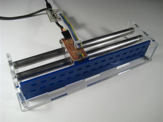
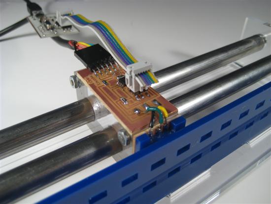
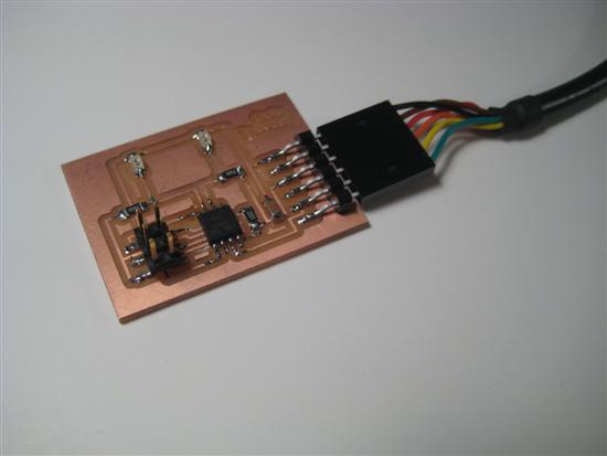
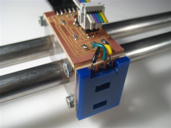
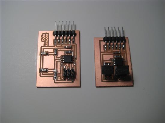
For learning and fun purposes I first build the Step Response capacitance sensor and tried it, which worked pretty well. I also fabricated a light sensor which also worked well. Then I added a second phototransistor at the light sensor board to use it as an optical encoder device.
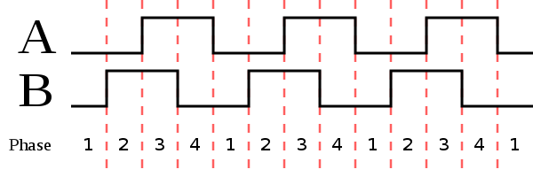
Bellow is the opening patter I made for the 2-zone relative (or incremental)linear encoder.
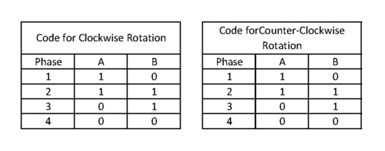
Bellow is the Grey Code rotary encoding scheme (picture from Wikipedia).
.svg.png)
Bellow: Reading values from Neil's Python code
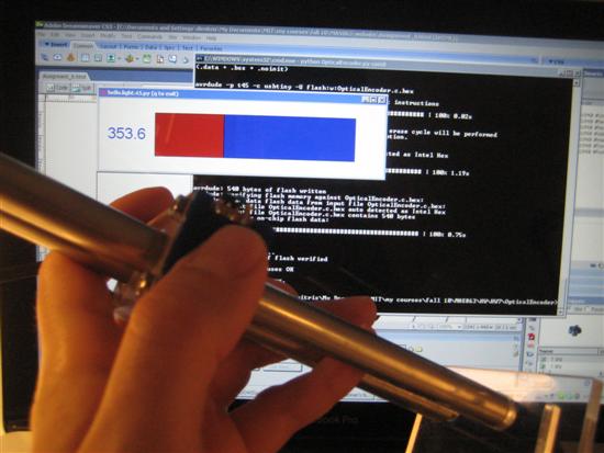
Bellow: Reading sensor values in Processing from my code.

Changes to Neil's hello.light.45.c code
I only modified the main loop. I iteratively change the ADMUX register to get input from PB3 and PB4 respectivelly, and I included a "5,6,7,8" byte sequence in addition to the existing "1, 2, 3, 4" to initiate the transmission of the PB4 pin's value. Here is the code:
// main loop
//
while (1) {
//
// send framing
//
////////////////////////////////////
// first phototransistor connected to PB3 starts here
/////////////////////////////////////
put_char(&serial_port, serial_pin_out, 1);
char_delay();
put_char(&serial_port, serial_pin_out, 2);
char_delay();
put_char(&serial_port, serial_pin_out, 3);
char_delay();
put_char(&serial_port, serial_pin_out, 4);
char_delay();
ADMUX ^= (1 << MUX0); //XOR
//
// initiate conversion
//
ADCSRA |= (1 << ADSC); //this is like a switch to intitiate ADC process...
//
// wait for completion
//
while (ADCSRA & (1 << ADSC)); // ..and also a flag to indicate that the ADC process is still taking place
//
// send result
//
chr = ADCL;
put_char(&serial_port, serial_pin_out, chr);
char_delay();
chr = ADCH; //chr = (PINB & (1<<3)) >> 3; //NEW
put_char(&serial_port, serial_pin_out, chr);
char_delay();
////////////////////////////////////
// second phototransistor connected to PB4 starts here
/////////////////////////////////////
put_char(&serial_port, serial_pin_out, 5);
char_delay();
put_char(&serial_port, serial_pin_out, 6);
char_delay();
put_char(&serial_port, serial_pin_out, 7);
char_delay();
put_char(&serial_port, serial_pin_out, 8);
char_delay();
ADMUX ^= (0 << MUX0); //XOR
//
// initiate conversion
//
ADCSRA |= (1 << ADSC); //this is like a switch to intitiate ADC process...
//
// wait for completion
//
while (ADCSRA & (1 << ADSC)); // ..and also a flag to indicate that the ADC process is still taking place
//
// send result
//
chr = ADCL;
put_char(&serial_port, serial_pin_out, chr);
char_delay();
chr = ADCH; //chr = (PINB & (1<<3)) >> 3; //NEW
put_char(&serial_port, serial_pin_out, chr);
char_delay();
}
Processing Code
This is the Processing code I built to read data from the Serial Port:
import processing.serial.*;
Serial myPort; // Create object from Serial class
int valPB3 = 0; // Data received from the serial port
int valPB4 = 0;
byte byte1 = 0;
byte byte2 = 0;
byte byte3 = 0;
byte byte4 = 0;
byte lowbyte = 0;
byte highbyte = 0;
void setup()
{
size(200, 200);
String portName = Serial.list()[0];
myPort = new Serial(this, portName, 9600);
myPort.buffer(1); // this sets the size of the buffer to 1 byte: it reads 1 byte at a time
}
void draw()
{
}
void serialEvent (Serial myPort) {
if ( myPort.available() > 0) {
byte1 = byte2;
byte2 = byte3;
byte3 = byte4;
byte4 = lowbyte;
lowbyte = highbyte;
highbyte = (byte)myPort.read();
if ((byte1 == 1) & (byte2 == 2) & (byte3 == 3) & (byte4 == 4)) {
valPB3 = 256 * highbyte + lowbyte;
println("Sensorvalue in PB3 is: " + valPB3);
//if (val1<300) println("1st sensorvalue is: " + "LOW");
//else println("1st sensorvalue is: " + "HIGH");
}
if ((byte1 == 5) & (byte2 == 6) & (byte3 == 7) & (byte4 == 8)) {
valPB4 = 256 * highbyte + lowbyte;
println("Sensorvalue in PB4 is: " + valPB4);
//if (val2<300) println("2nd sensorvalue is: " + "LOW");
//else println("2nd sensorvalue is: " + val2);
}
}
}
Next Steps
For next steps I want to build a better and more precise encoder and include it in a closed-loop cnc XYZ machine.