Input Devices
Concept
What I wanted to do was create a device to measure water levels in soil. Ideally I wanted to build a low power (solar or battery powered) device that would measure water levels and flash a green LED when a measurement was taken. If the water level was too low, then it would flash a red LED.
Test Circuits
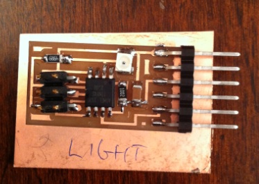
First I tried to create some hello world circuits:- Light
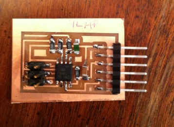
- Temperature
- Load
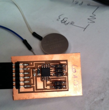
First pass: 0 for 3.
Each circuit managed to load the respective program. Good sign. But when I tried to display the data in the Python program, only garbage readings would get reported. Dang. Since this was true for all 3 circuits, I assumed the issue was with the serial communication.
Focusing on the Light board, I found that the voltage across the light sensor was not changing. This lead me to discover that the resistor that was suppose to be 49K was actually only 49 Ohms. I removed the bad resistor and soldered in a non-surface mount resistor that was not too far off. It Worked!
Similar debugging for the Temp sensor did not reveal the source of the problem. I never got this to work. The wheatstone bridge looked good. And the resistance across each resistor followed the R= (1/ (1/R1) + (1/R2)) rule.
For the Load circuit, I realized that I really didn't understand what I was supposed to be doing. Thinking about how to do the water sensor helped me understand that the Load circuit was about.
I wanted to measure the resistance across two nails that are near but don't touch. The assumption is that if the nails are in moist soil, the would start to conduct and the resistance would drop.
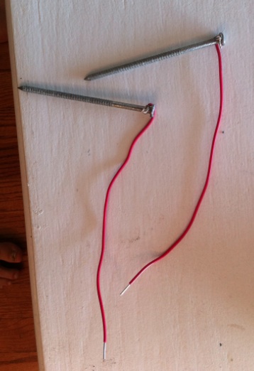
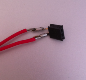
I put a header on the other end of the leads to make it easy to attach to the Load board.
You can barely see the response. The middle bar goes from over 1000 to about 850 when the nails are submerged.