Output Devices
This week we had to make an output device. My plan was to run a DC motor to drive a toy car.
Since I was following one of the example boards from the class website (found here), I thought everything would be fairly straightforward. However, I ran into more trouble than expected. I milled and stuffed my DC motor board without any difficulty, but when I plugged in the battery, both my battery and my board quickly overheated. I could not program the board at all.
I thought this overheating was a short circuit and a sign of crossed voltage and ground paths. I checked my traces and components with the multimeter, but everything seemed fine and I couldn't identify any crossed paths. I removed and re-soldered components one by one. But I still couldn't find what was wrong.
Someone told me that I had used the wrong MOSFETs (apparently I accidentally used the P-channel and instead of N-channel), so I tried replacing the MOSFETs. Still no luck.
failed DC motor board
I decided to make a new DC motor board. ....and it started smoking as soon as I plugged in the battery! I ran into exactly the same issues: no crossed VCC and ground paths, yet there was overheating.
We received an email from Prof. Gershenfeld about the H-bridge component. I wasn't sure if this meant that we had the wrong H-bridge in stock or if I had used the wrong board with the H-bridge we had available. I don't know if the H-bridge was the reason my board was not working, but since we did not have the other type of H-bridge available in our shop, I gave up on the DC motor.
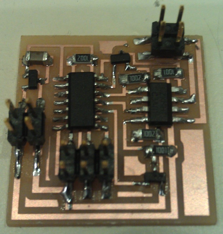
At this point I decided to work on the servo motor (board provided on the class website here) instead. Again, my board began overheating. But this time, I could actually debug it! The multimeter told me that the voltage and ground paths were indeed connected. I found that a small drop of solder had connected the VCC pin of the ISP connector to the ground trace. I removed this solder with a solder braid, and the problem was fixed!
my more successful servo motor board
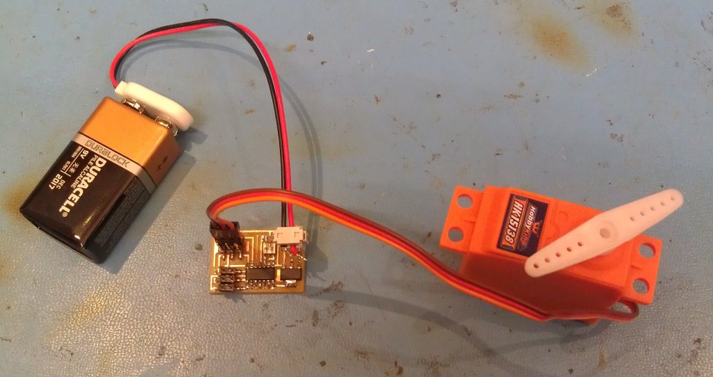
I programmed the motor board with the example two-channel, PWM software C file on the class website here and uploaded it via my FabISP using Arduino. And it worked! Well, sort of. Instead of the shaft rotating, the entire motor body moves:
I tried out different servo motors, and this happened with every single one. I don't know why. Because I could not get a motor shaft to actually turn (and because I built several boards and ran out of time), I did not end up building the car.
Files
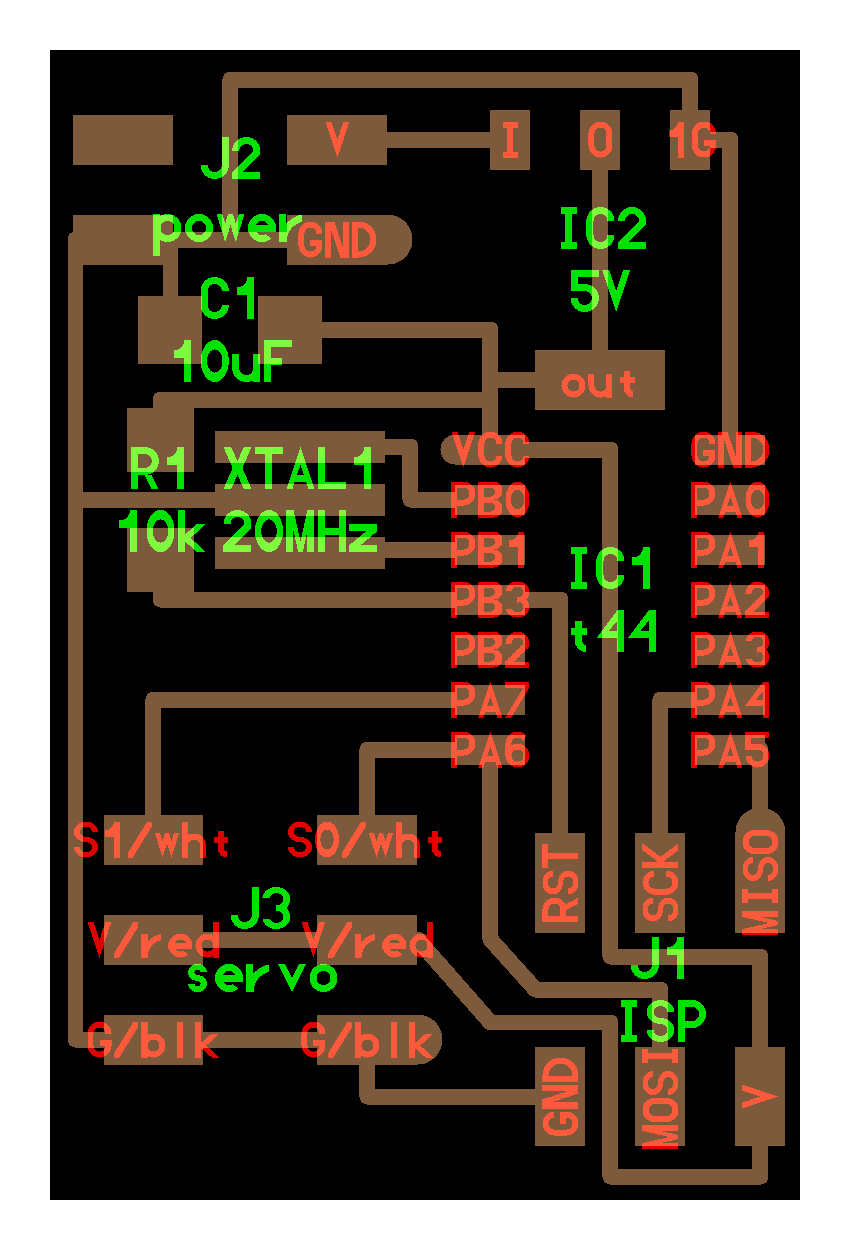
servo motor board traces
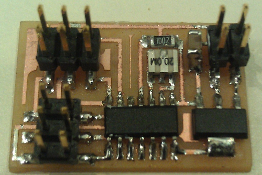
servo motor board interior
servo motor two-channel software PWM C