FabISP In-circuit Programmer
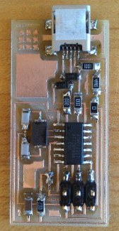
This week I built a very small programmer. How small? This small:
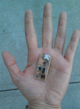
This little circuit board will be utilized to program other circuits later in the course.
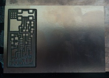
My first step was to mill the board using the Roland Modela. Luckily, I didn't face any problems. I used double-sided tape to stick the board to the substrate that sits on the machine, and I tried to make sure the board was level without any bowing. I used a 1/64 endmill for the traces and 1/32 endmill to cut out the board. I loaded the png files provided by the class into the Fab Module, which I used to convert the .png into an .rml file and then send the file to the Modela. You can find the traces here and the outline that cuts out the board here.
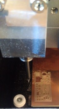
Freshly-drilled traces:
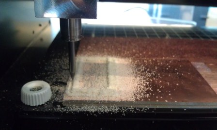
Cutting out the board:
I soldered each component to the board, following the guide here. I set the soldering iron temperature to 720 °F, and I started with the shorter components and ended with the taller components. This was my first time soldering, so it took me a little while to get the hang of it. But I think it turned out ok:
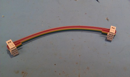
After I finished soldering, I put together a ribbon connector that will allow me to connect this ISP to other circuits in order to program them.
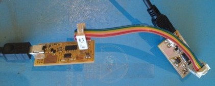
Done with constructing my hardware, I moved on to programming my ISP. I could not find the AVR programmer to connect my ISP to the computer, so I used someone else's already-working ISP to connect my circuit board.
I programmed my ISP with the firmware provided on the class website; you can find it here. I followed the assignment instructions (at the bottom of this page) and typed these commands:
make clean
make hex
make fuse
make program
However, I encountered a problem. "Make fuse" worked fine, but then "make program" failed. I decided to start over again, but during the second attempt--and third, and fourth, and fifth attempts--"make fuse" was failing, too. I figured my soldering was good and all my connections were made because "make fuse" did work initially. I thought there might be a problem with one (or more) of the components, but admittedly I know nothing about how electronics work (yet).
I talked to Rob, a TA, for help. He suggested that I check out my 20 MHz crystal. Rob explained to me that the crystal is like the clock of the circuit. The crystal sets the internal timing of the circuit, and when I tried to load a new program into the circuit, the program changed this timing. Perhaps the crystal was out of sync. (I apologize if my explanation of this is wrong; honestly I'm still not sure how this all works).
I replaced the crystal and tried programming again. No luck. I thought maybe the problem wasn't with the crystal itself but with its associated components. I replaced the capacitors linked to the crystal and tried yet again. This time, the firmware worked!
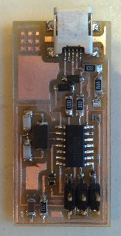
After successfully programming my ISP, I de-soldered my jumpers. Here is my final product:
Now I'm ready to program electronics! ...well, ok, first I need to learn a litle more about how electronics work and how to program them. I look forward to learning all that in upcoming weeks.