Electronics Design
This week we had to design and fabricate a circuit board with an LED and button. Designing the board was fairly simple because we were given the components and most of the layout, which you can see here. All I had to do was figure out where to place the LED and button.
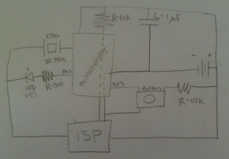
First I wanted to understand what was going on in the board, so I drew out a simplified schematic by hand. Once I had a good idea of how the current was flowing through the components, I was able to see where to put the LED and button.
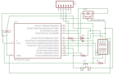
I translated my drawing into a mill-able schematic in a program called Eagle, which was fairly straightforward. I found the components in the fab and sparkfun libraries. I used the sample board linked above to map out which pins connected to which on the components.
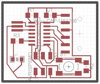
After completing the schematic, I moved to the board. I placed the components where I wanted them and chose the automatic option to create the traces, which were set at 0.012" width. The traces weren't exactly where I wanted them so I moved them around a bit. I then drew a border (for cutting out the board) on the dimension layer.
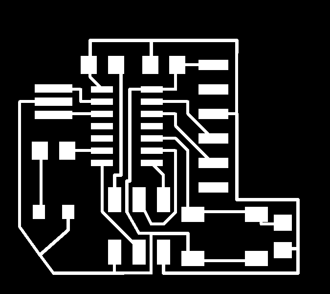
I exported the traces and border as monochromatic images at 1500 dp on the clipboard and pasted them into Paint. I assumed that everything was fine, but when I opened the files on the fab module for the Modela they were humongous. They couldn't even fit within the size of the Modela's bed. I didn't know why the png files turned out so large, but I thought it might have to do wtih Paint. I tried to export the images again, this time at 500 dpi and saved in a folder instead of copied on the clipboard. I opened the files in Photoshop, inverted the colors, cropped, and saved them. This seemed to fix the problem, and I was able to mill my board without any further issues.
My traces:
Modela milling:
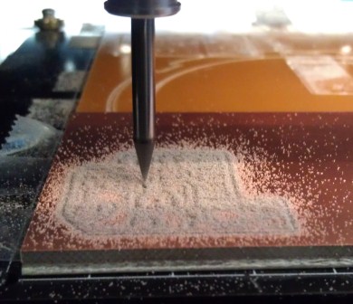
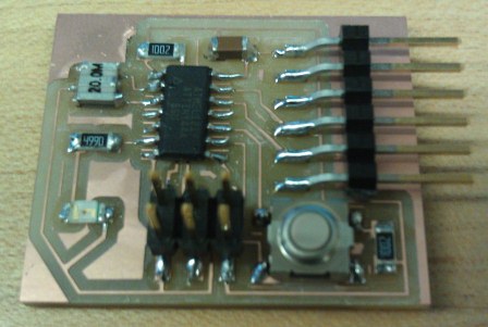
The traces turned out a bit too thin. I think 0.012" isn't quite wide enough (although I don't think there will be any problems with the electrical connection), and next time I will set the traces to 0.016" width. Soldering this time went more smoothly than a few weeks ago. I guess I'm getting used to it! Here is my final board:
Files