
 The project started like this: I was incredibly sick, and hadn’t gotten much work done because of my Sci-Fi 2 Sci-Fab class final project. But I had to solider on! So, I made myself some chicken soup and went into the lab to get started on the window blinds.
Let’s review for a bit… for my final project concept I proposed making blinds that are opened and closed automatically according to the amount of sunlight striking the window. From a comfort perspective, this makes total sense: when we are around the house, we’d like to have an optimal amount of sunlight during the day, but at night we’d like to have privacy. Maybe some people would say that messing with blinds is a pain in the ass. I don’t agree with that opinion, but here is what I think: automatically opening and closing blinds could have a profound effect on how you sleep and feel during the day. I do a subscribe to the idea that comfort and productivity are optimally achieved only after a primal hierarchy of needs is met. That is to say that to achieve mental flow, it is important for one to have his or her basic needs met, and one such need is to regulate your circadian rhythm by controlling exposure to sunlight.
What I am aiming to do is to create a proof-of-concept and example of a product that promotes quality of life by regulating exposure to sunlight in an appropriate way.
So, here is some documentation on how I got the blinds to work.

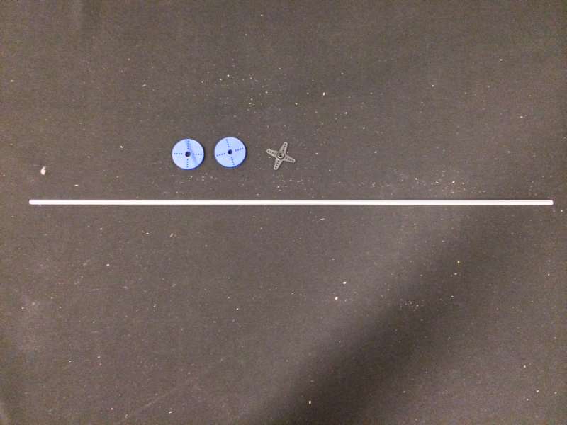
First, a list of parts:
- Aluminum frame (or some other strong, light-weight frame)
- Venetian blind parts (loop string, drum cradles, hex rod, blind drums, blind cord)
- Servomotor (capable of 180 degree range of motion)
- Solar powered battery supply
- Acrylic (for the enclosure and motor adapter)
- Custom circuit with ambient light sensor and PWM output for servomotor
Lucky for me, my sister had ordered custom blinds but got the wrong size. So I shipped the blinds all the way from Cleveland, Ohio to the Media Lab and reverse engineered them. I looked up the anatomy of venetian blinds and thought about purchasing blind parts from this site. My approach was to reverse engineers the set that I had and try to implement the parts on my own one by one. However, since I had a fully-working set and I am now a poor grad student, there was also great temptation to use as much as possible from the blinds so that I wouldn’t create waste.
Motor adapter cut by laser cutter from acrylic. These two component connects the servo to the hex rod.
I decided to first start by testing whether my servomotor would have enough torque to open and close the entire set. So, I created a motor adapter for the servomotor to connect it to the hex rod. I created a circle that attaches to the servo, and then cut another circle with a hexagonal slot in the center. I tied the adapter together using metal wire. This was cheap, worked well and it also allowed for some slack to account for the stopping behavior of the servo. The layout for the custom circuit can be referenced in my output devices project.
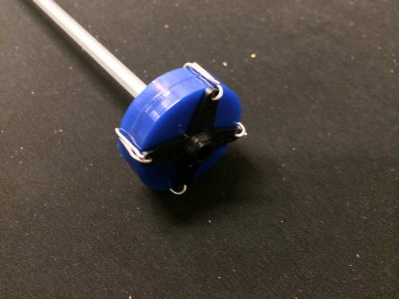
Connected the gears using wire.
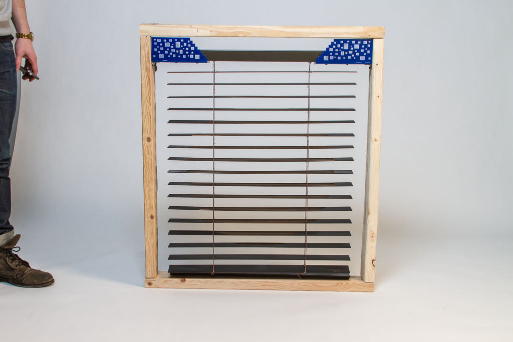
I was quite happy to find that the size of the servo I’d chosen would provide enough torque. The next step was to modify the blind set and cut the loop string. I had to remove the old manual mechanism used to tilt the blinds, and in order to make an aesthetic demo, I decided to shorten the loop string by nearly half the length. I found that since the loop string was made from nylon, I could use a blow-torch to close the cut ends of the string and get rid of the fray, which was key to fixing the string.
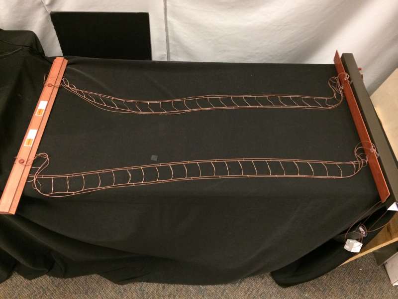
String loop modified
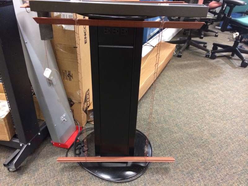
Blinds had to be shortened to fit the presentation frame for demoing.
After shortening the string, the challenge was to create an enclosure. I made a parametric enclosure out of blue acrylic, using SolidWorks. The parameters depended on many things: fitting the dimensions of the servo, solar-powered battery, printed circuit board, aluminum chassis and position of the hex rod. This was really tricky to get right, I had to use calipers to measure everything and make educated guesses about the press fit of the material, but eventually I came up with these laser cut designs. Panels for the front, back, and bottom are all press fit. The bottom panel screws to the aluminum enclosure.
Enclosure designed in SolidWorks, lasercut acrylic. Houses the motor and electronic components.
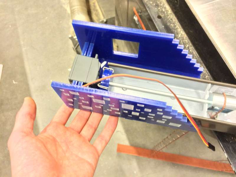
Servo in the enclosure
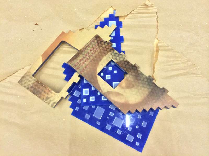
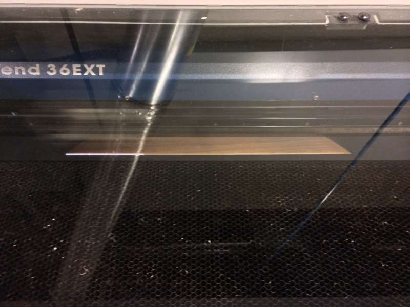
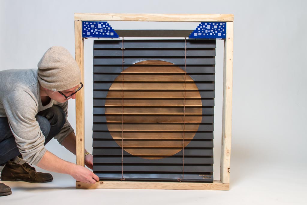
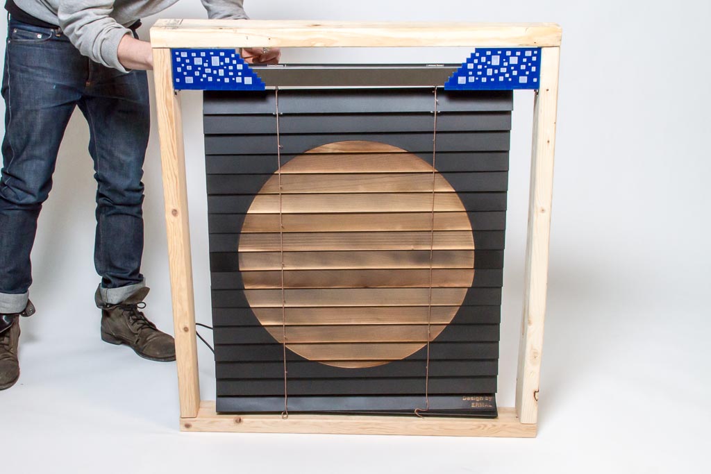
Next step was to modify the slats. I spray-painted them black and then lasercut a design. I wanted to place something minimal and iconic on the blinds. Some people asked why I chose the circle… that’s because the shape is simple and symbolizes the sun. Believe it or not, etching the circle was really tricky to do, as I had to measure the overlap and draw the circle regions that intersect with the overlap for each slat. If you were to spread out the blinds and lay them flat, the design would look more like an oval.
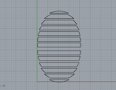
Made a design in Rhinoceros of a circle interesection with overlapped blinds. I was able to calculate the design for each slat this way
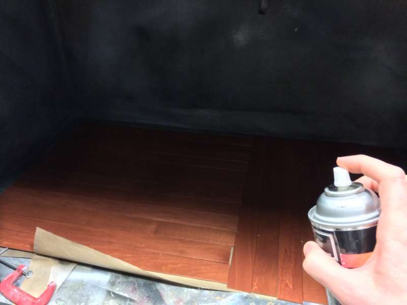
Painted the slats using black spraypaint. Waited about 30-45 min to dry.
Used Raster mode on the laser cutter, at 100% speed and 40% intensity, it went through the paint and partially into the material.
The raster on each blind went partially into the material to reveal something beautiful. The slats looked so much better this way–and the circle gave that “reclaimed wood” feel, which I really enjoyed.
I knew that to make a good demo, I had to make a window frame, so I found some scrap 2×4′s and made a shoddy window frame with some L-brackets to hold up the aluminum frame.
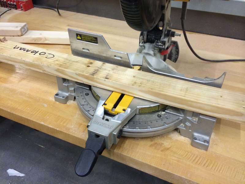
Cut 2×4 material to make window frame.
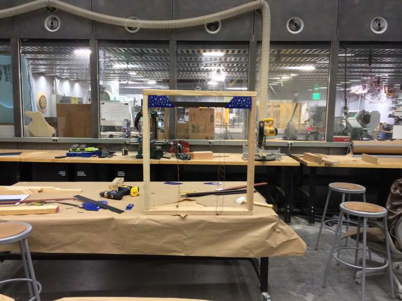
Window frame completed, holding the aluminum frame
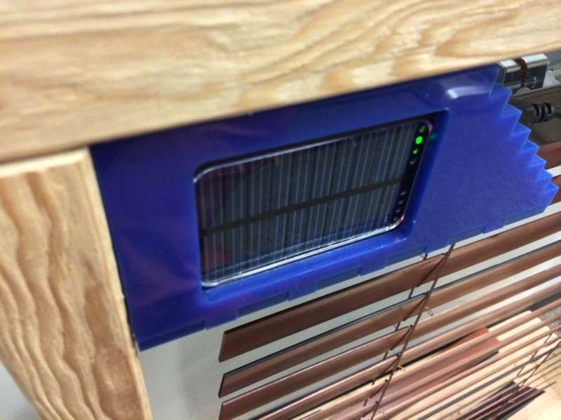
Solar-powered battery power supply on one side
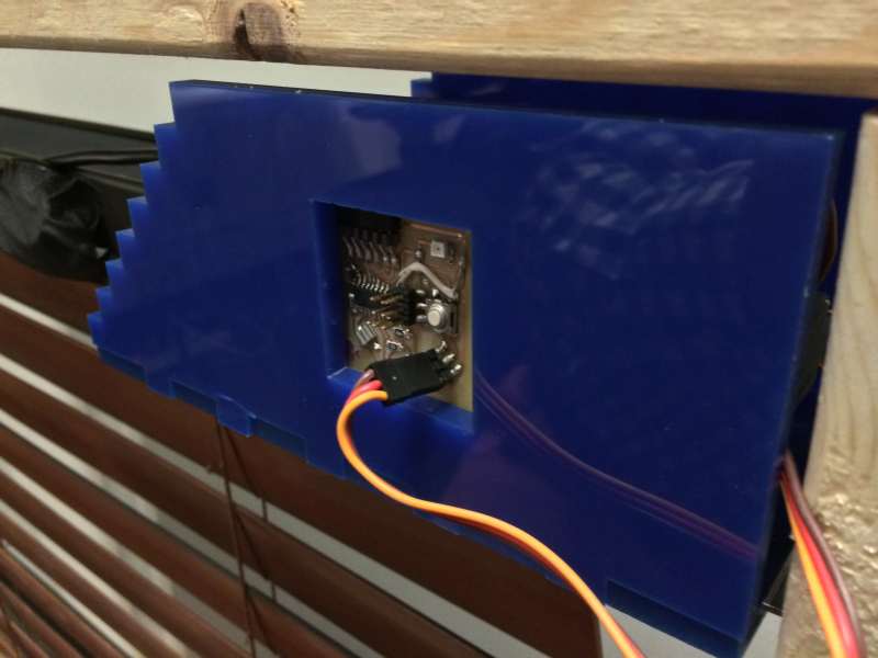
Custom circuit running the servo on the other side
Then just had put the slats in one by one and here are the results
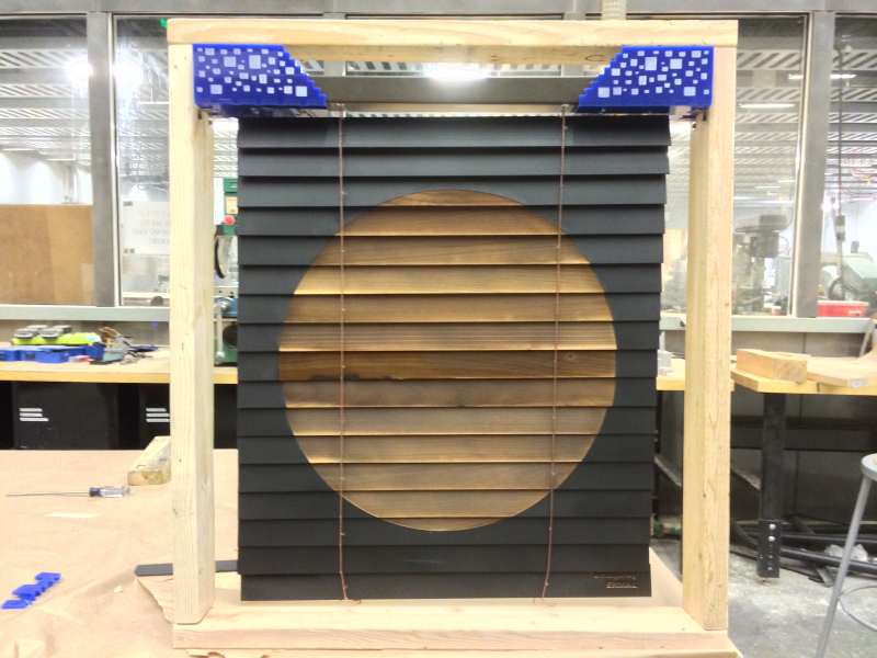
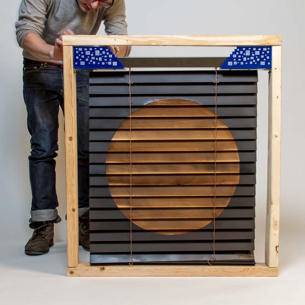
Ambilinds final result.
Video demo
The production shots are below
And that’s it!
Big ups to Matt Carney for the intro to mechanical design, and Jeff Duval for hooking me up with a servo and his great suggestions.
Pingback: [0] Concept of Final Project | How Ermal Makes (Almost) Anything