

I’ve been thinking more and more that my current projects should be contributing to my final project, so that I don’t waste time. We were tasked to make a circuit with a sensor, and measure something.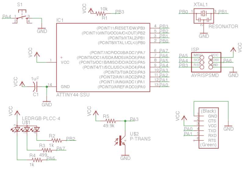
Luckily, for my final project proposal, what I need is a component that is well-understood and readily available for surface mounting: a phototransistor. A phototransistor can be used to measure the intensity of light striking the sensor, which I can use to roughly determine the level of daylight outside. With this circuit, I can control a motor to open window blinds to let the right amount of sunlight in at appropriate times of day, but as it gets darker, the blinds will close more and more until at total darkness they will close, for privacy.
I’ll gloss over the details on how to use the Roland Modela MDX-20 milling machine (for that you can refer to the first PCB fabrication project. However, I did take this opportunity to experiment with design techniques, and arrived at a circuit that I’m very happy with.
First, from my previous posts (design a circuit and embedded programming), I was struggling to get the RGB LED to light up properly.
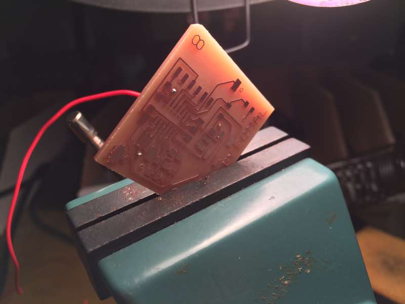
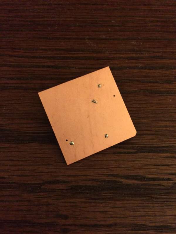
Soldered a via tip on the front, and cut the wire from the back
I’m happy to report that the issues have been resolved: I can now fade and switch red, green, and blue at will. Debugging the issue proved a pain because, as it turns out, there were actually TWO bugs in the circuit, which both contributed to form bizarre symptoms.
The first issue was that the pins on the LED were mislabeled. In the fab EAGLE library, the anode and green pads are swapped. I had already determined this and rectified the issue, but was still seeing a pesky issue: I could only fade one color, while the others acted like switches (on/off).
Vias must be connected to the ground plane
I determined that the fading for two of the colors wasn’t working because I had connected them to pins on the ATTINY that did NOT support PWM. In order to fade LEDs, you have to be able to generate a waveform and alter the duty cycle. This can be done in software, but better to just connect the LED to a PWM pin.
After the ISP is connected to the pins on the ATTINY chip, that only leaves 1 PWM free! OH NO, wat do, wat do? Turns out you can use most of the ISP pins as GPIO (something which I hadn’t thought about and didn’t hear Neil mention in class). After I made this discovery, I was quite happy!
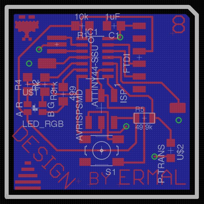
Finally, the finishing touch was to create a ground plane. This time, I wanted to make my routing easier and didn’t want to use any bridges. Further, I wanted space to place a couple of pads to pins on the ATTINY, I could use these pins for output devices (to drive a motor, for example), without having to redesign the whole thing.
A ground plane appears
Finally, as documented in my embedded programming project, I used the High-Low Tech Guide on programming an ATTINY with Arduino.
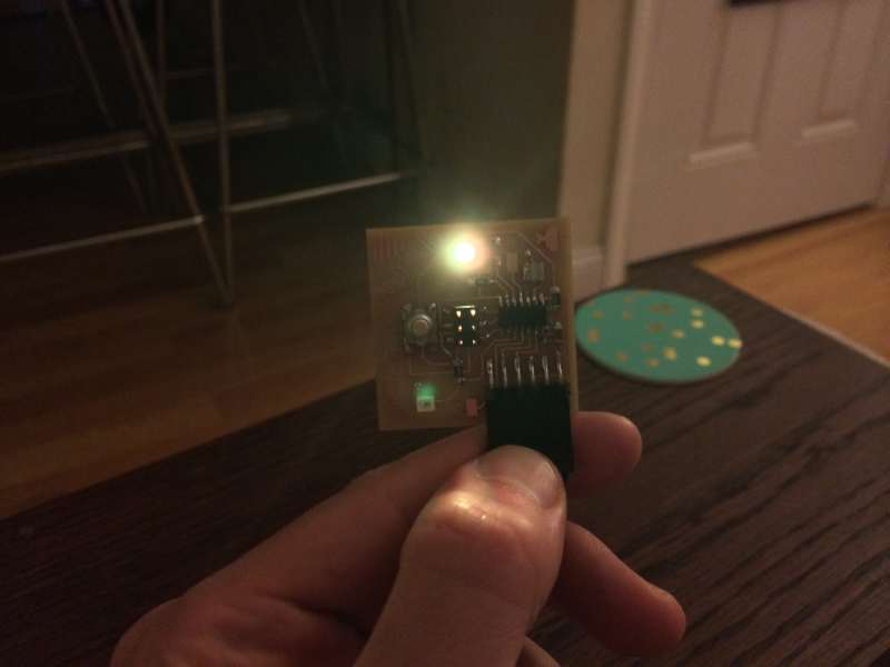
Phototransistor level is reported through LED–yellow means daytime
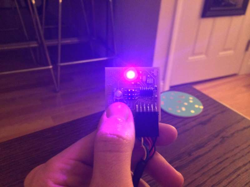
Phototransistor says it’s night time (purple color)
One final word, since I wanted all of these nifty features AND wanted serial communication via FTDI, I had to substitute the ATTINY-44 for the ATTINY-84, which is the same but can store 8KB of instruction. This is because you have to use the software serial libraries, which take a lot of space. ATTINY does not have a hardware serial port, so you must use a software solution.
For posterity, here are the resources:
-

- Top layer

-

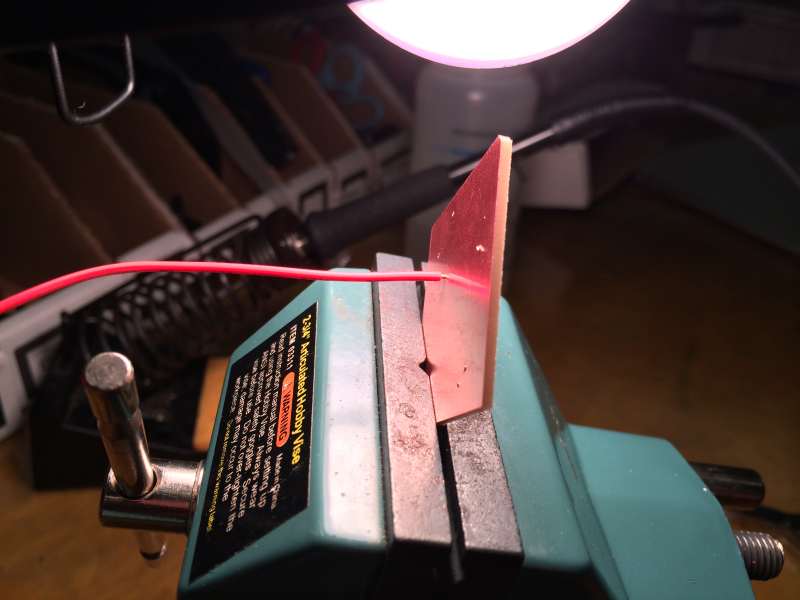
- Cutout with vias

With the embedded program, I can use the button on the circuit to calibrate night time/day time light values. Theoretically I should just be able to do this once in the morning and once in the evening, and the blinds will shut according to the amount of light visible outside!
Pingback: [12] Application Programming – TableTop Object Detector | How Ermal Makes (Almost) Anything