Redraw the echo hello-world board, then add (at least) a button and LED (with current-limiting resistor). Then, check the design rules and make it.
So I actually really enjoy electronics design and production. I'm not amazing at it, but I do enjoy it and feel like, if I'm actually going to get good at anything, it may be this (but in the far distant future).
For this project I got to (had to) learn how to use a circuit design software, and I chose Eagle, as it seemed to be a pretty standard software that my TA buddies could help me with whenever they stopped by my desk for a secret snack, or tried to sneak off to the bathroom.
I think my biggest struggle with Eagle was figuring out how to load the FAB library. For some reason it had a hard time locating the library where I had saved it on my desktop. After I moved it into the Eagle lbr folder things went smoothly.
My modus operandi is usually to struggle with the assignment/software for about three days of my life, and then after tons and tons of rabbit holes, gain a general understanding of what I need to do, and then have aforementioned TA buddies come to my rescue and help me fix what is wrong with my plan. Not this week guys, not this week. This week I had the fortune of stumbling upon Pip Mothersill's page from the 2012 year of HTMAA. Pip is my personal hero. Her webpage was documented amazingly well, and if I stumbled across any issues, I just went back to Pip's page and she usually had had the same problem and documented the resolution. I will probably be buying Pip a present at some point.
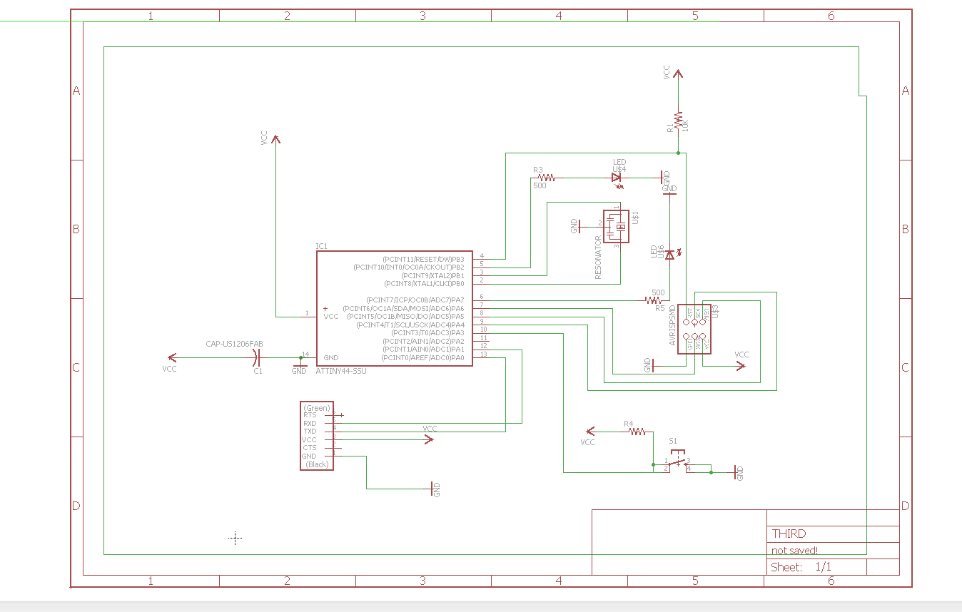
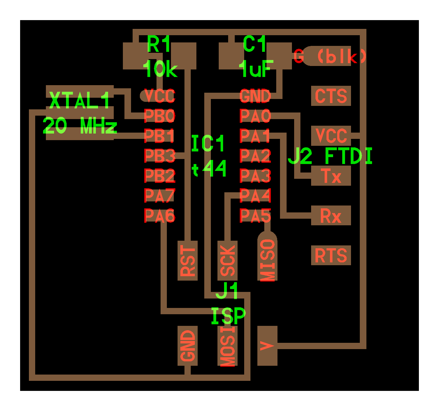
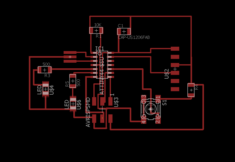
As you can see from my schematic, I only added two LEDs. I had tried three, but after several hours of trying to create a route that wasn't too narrow, decided to sacrifice my third LED so that I could get the project done. I may come back to figuring out the mystery of the third LED at a later date, because who am I kidding, I'm after the pretty lights. I had tried to run four traces through the center of the microcontroller, but when I loaded the fab.dru file to check for errors, I continuously received proximitely errors. After I finished my board with two LEDS, I tried readding the third LED, but I still couldn't find an elegant solution, other than including a 0 ohm resistor, which kind of feels like cheating. So I stuck with the two LEDs.
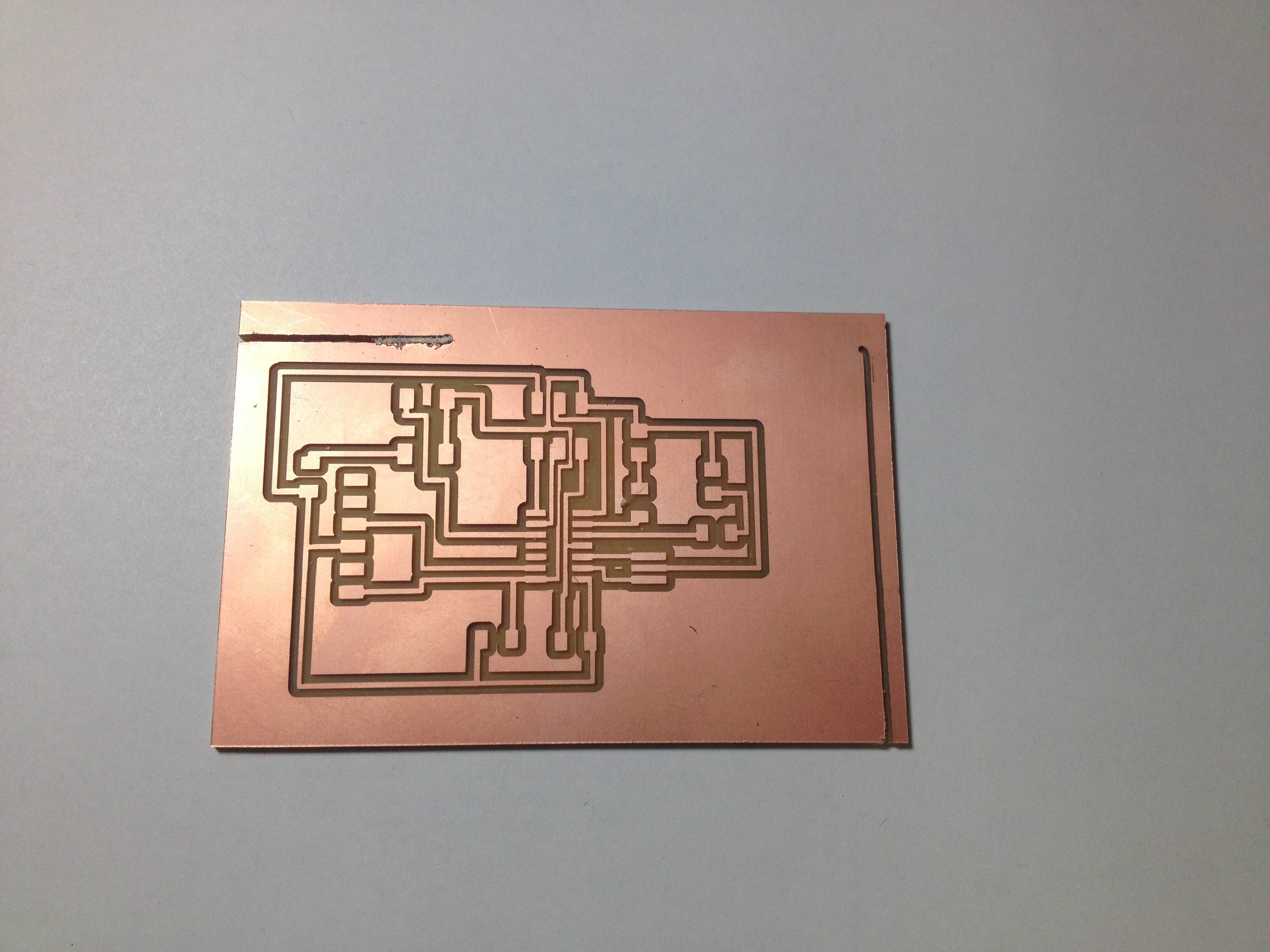
After I exported my board and outline, I tried milling on the Modela. I say tried, because I forgot to make my PNG black and white. Apparently fab modules weren't a fan of my red traces. After I realized, and fixed my mistake (all with the help of Pip's page) things went smoothly on the traces.
The outline however, was not so great. I didn't make the correct size, so it began cutting an outline much larger than my board. This general unhappiness caused my board to lift, and I ended up canceling the job to save my design. This left the outlines of my board half-cut, but I decided I could live with this, as it is largely an aesthetic issue.
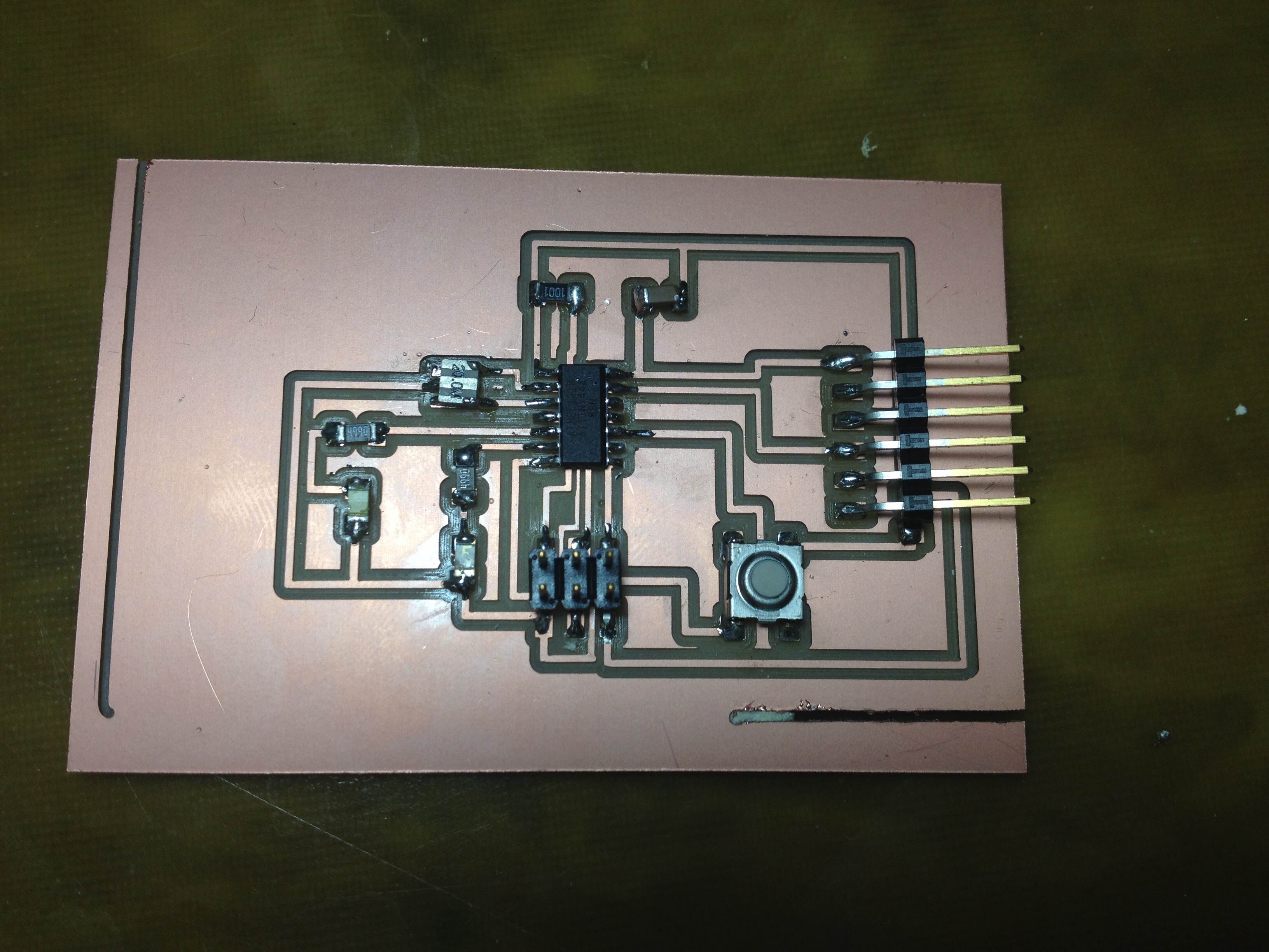
Soldering is my favorite. It's the best, most theraputic, activity ever. I had the board stuffed in about an hour, which is pretty fast for me. I used lead solder, and chose blue and green LEDs. As usual, I had a rough time soldering my resonator, but got there in the end. Also, for some reason I placed a resonator right behind the ISP and so had to solder the ISP at a weird angle, but I think it will work. I did notice the next morning that I had placed one of the LEDs on backwards, so will need to fix that.
I haven't had the chance to program my board yet, so whether it works or not, remains a mystery to be solved another day.