
Add an output device to a microcontroller board I've designed and program it to do something.
This week I decided a good use of my time would be to design the circuit board for my final project: my grown-up lite brite.
This example that I found online has approximately 300 individual units that when turned, light up, and change colors. I decided that for my lite brite, I would have to scale back for a work load that I can handle, as each unit is going to need an individual circuit board. I originally priced out my circuit boards through a board house, thinking maybe I could save myself some time, but decided I didn't want to pay the $700 it would cost to have them made. That means, I get to make them. Guess what I will be doing over Thanksgiving break.
So I decided to make the units of my board in a honeycomb shape. I sourced a 2'x4' piece of PVC and have decided that each unit will be accomodate a 2"x4" circuit board to save myself some milling time. The circuit boards will nest inside their individual honeycombs, and then be covered with individual pieces of thin, frosted acrylic. The idea is then, that a user can tap on the acrylic, and using capactive touch, the LED in the circuit board will be programmed to change colors.
When designing my circuit board I need consider two things: 1) how will the touch register on the board, and 2) how will my board get power.
My TA pals and I decided the best way to solve the touch issues, was to use the two unused pins on my ATtiny45 microcontroller, and have large traces circling the board so that when users touch the board, the traces will send the signal to the pins, and light up the RGB LED.

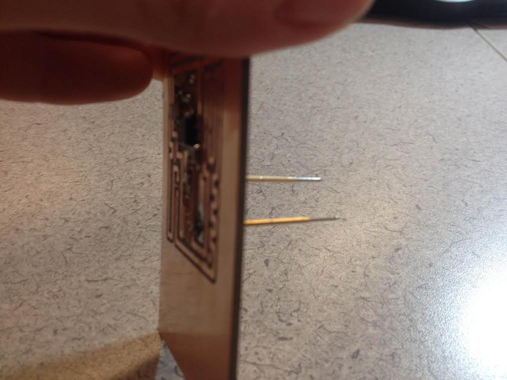
Powering the board is a bit more difficult, but said TA pals proposed that I try pogo pins. The idea is to mill two holes in my board: one for the VCC and the other for the ground. Then, under my PVC, I would have a layer of foam, and then one of the pogo pins would make contact with the VCC, while the other pogo pin would continue through the VCC layer, through another piece of foam, and then make contact with the ground.
To make this work, when routing the board in Eagle, on the dimension layer I needed to design two holes that lined up with the pads that I set for ground and vcc.


I had some issues with the fab modules. I would send my board to mill, and half would mill, but the other half would barely etch. After approximately four attempts, Will rolled back fab modules to an older version and I had no problem.
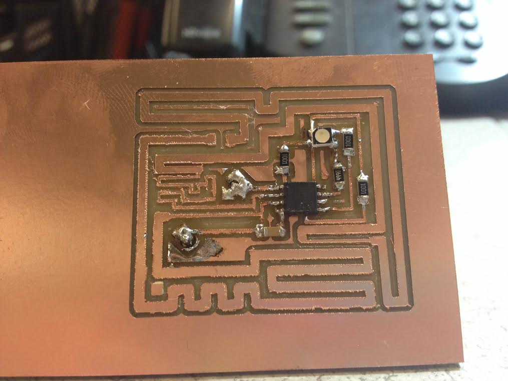
Somehow I drilled the holes for my pogo pins to be WAY too big which made for awkward soldering. Also, the soldering tip in the CBA shop was enormous. I felt like I was trying to solder with a giant crayon. My soldering job isn't quite up to standard, but I have decided to make some changes in my design anyway so I will get the opportunity to tweak some things before I mass produce my boards.
So I didn't get a chance to try programming my board because of my horrible soldering job. The solder on my microcontroller is way too clumpy, so that the clamp that I'm using to program couldn't fit appropriately on the microcontroller. I guess this will have to wait until next week!