Making a Desk for My Office
Overview
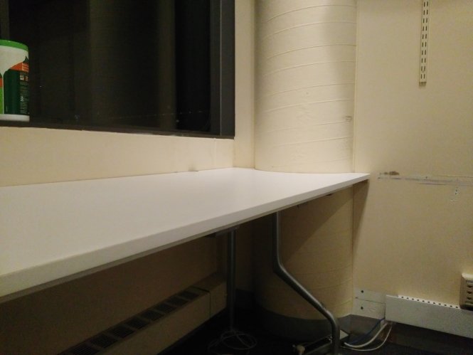
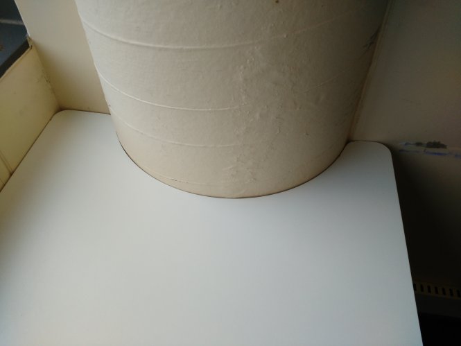
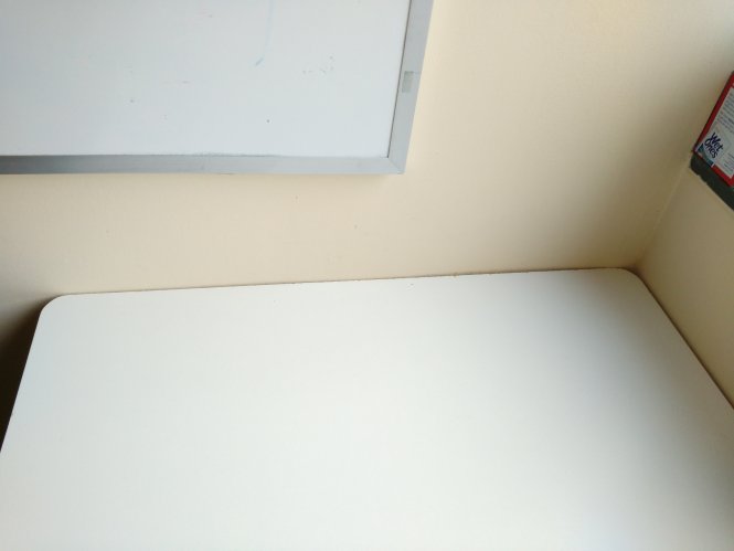
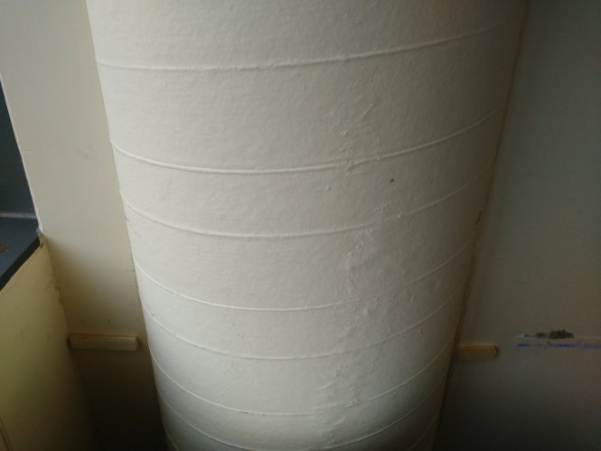
One of the walls in my office at the MIT Media Lab has a peculir characteristic. A large circular pipe is partly embedded in the wall and about 40% of the pipe is coming out of the wall. Consequently, the space near that pipe is largely unusable. Moreover, even if a desk is placed such that it touches the column, items still cannot be placed near the edge of the desk as they may fall off. I wanted to make the best use of the space in the office, so I decided to build a desk that would follow the curvature of the pipe and go around it right up to the wall.
| Before | After |
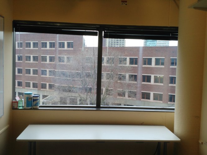 |
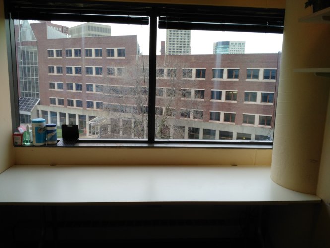 |
In the sections that follow, I will describe the process I went through to complete this project, explain some of the challenges, and discuss some of the things I learned and discovered along the way.
Acquiring Geometric Characteristics
The main challenge for this project was going to be to determine the geometry of the pipe, becase less than 50% of it is coming out of the wall. Thus there were two nontrivial non-indepenment features to be determined: (1) The radius of curvature of the pipe, and (2) the percentage of it that is coming out of the wall.
I performed a brief web search for a tool that could measure the radius of curvature of a surface, but I could not find any. This presented an interesting opportutity for innovation. An instrument that can find the radius of curvature of a surface based on a small sample of the full surface would be of tremendous utility for applications like this one and potentially hundreds of other applications. In fact, in any situation where we wish to create a CAD model of an existing curvad surface, we would need to know the radius of curvature of the object. One potential method of creating such tool is by using a bymetallic strip in reverse, together with a heater, a temperature sensor, and a pressure sensor. The bymetallic strip has radius of curvature that is a function of the temperature experienced by the strip. We can table that lists the relationship between temperature and radius of curvature for the metallic strip. Then we can wrap such a metallic strip along a portion of the surface whose curvature we are trying to measure. The strip wants to maintain a particular radius of curvature corresponding to the ambient temperature, but when we wrap it against our surface, the strip is under stress and not in equilibrium. We could then have an indicator that tells us when the strip is under stress. Then, we can heat up the strip until the stess indicator (pressure sensor) starts indicating that the strip is not under stress anymore. Then, we record the temperature value at which the strip is in equilibrium in its wrapped state. Finally, we look up this temperature value in the table we created earlier and from the table we read out the radius of curvature. We can put all of aforementioned components of this system and create a handheld device out of it.
Another possible solution is to use laser reflection. This method, however, would be less versatile, more expensive, and would require a special platform on which a sliding laser would have to be mounted.
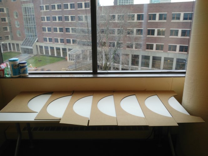
Since it was not going to be possible to determine the geometric profile of the column through measurement, I had to seek an alternative method. My best option was to make a template design based on an initial guess, laser cut the templace out of cardboard, and then progressively refine my initial guess in an iterative approach - where with each iteration I would laser-cut a new template or reuse the one from the previous iteration if possible. That is exactly what I ended up doing, and in the process I found some very unexpected results.
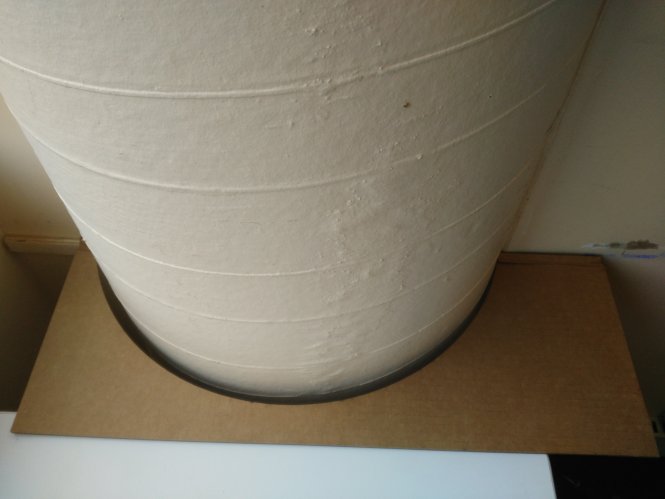
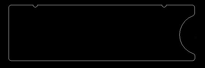
Initially, I had to determine the two aforementioned paramters - radius and percent protruding from the wall. Subsequently, however, I also had to worry about a third parameter - distance to the nearest wall. I was able to find the radius in only 3 to 4 iterations. The other parameters proved to be more tricky because of something quite unexpected. As it turned out, the side to the left of the pipe was not at the same level as the side to the right of the pipe! There was a difference of full 5mm between the two sides, which was completely unintuitive. Therefore, it took me about 10 iterations until I was able to find the correct geometric profile for column and walls. Here is the final template.
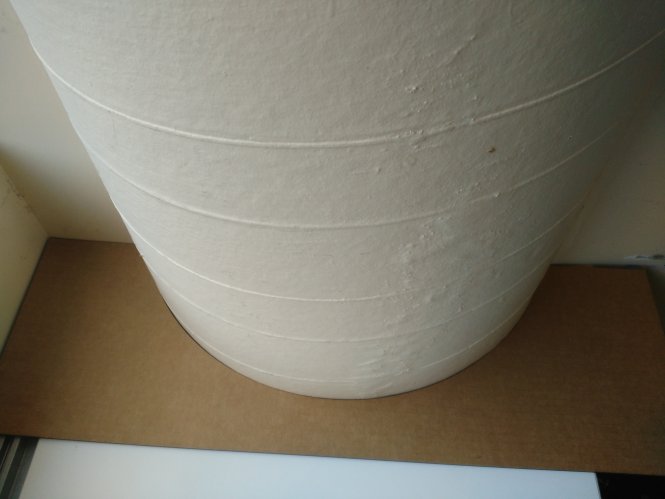
Some of the templates I was able to reuse, thus I had to laser cut only 7 templates in total.
The last remaining parameter I needed to find was the width of the room. I already knew that the room width near the window will be 5mm less than the room width measured on the other side of the column. I made some measurements with a measuring tape, but a measuring tape always introduces about 3mm of error at the point where it needs to bend. The measurements I got were 230.3cm and 230.8cm plus/minus 3mm. Since I wanted my table to have the perfect fit, I needed better measurements than what could possibly be achieved with a measuring tape. Thefore, I used the ShopBot to cut a narrow block of wood of length 5cm by 231cm, which I then used as a high accurary measuring tool. I cut the piece slighly longer than needed and then I sanded off 1mm at a time and test fitted it in the room after each sanding job. With this approach, I was able to get a nearly perfect measurement for the width of the room to the left and to the right of the pipe.
Design and Fabrication
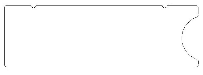
At this point, I had all required geometric information and was ready to design my tabletop. I made the width of my tabletop slighly larger than the supporting table, both for aesthetics and practicality. In addition, I also added semicirclular cuts where cables could go through. A picture of the final design is shown below.
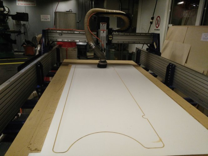
Next, I saved the SolidWorks design as a DXF, and then I imported it in PartWorks2.5D to generate the toolpath for the ShopBot. There were certain tricks I did here. The material I was using was quite expensive, so I wanted to save as much of it as possible. I could use the board's edge as my table's edge, without having to cut one side. But if I were to simply align my design tangent to the edge of the board, the endmill was still going to go through that path in air. In order to save this trip, I deleted the vector segment corresponding to the edge in question, and then I aligned the remainder of the design parallel and coincident to the edge of the board.
The second tricky task I had to do in PartWorks was to join all segments into a single vector. , I selected all segments and went to "Edit">>"Join Vectors". After this, I generated a profile toolpath, saved it, and imported it into the ShopBot control software to begin cutting the material. The job completed in about 15 minutes.
Download the design files here:
OfficeDesk.SLDPRT
OfficeDesk.crv
OfficeDesk.DXF
Installation
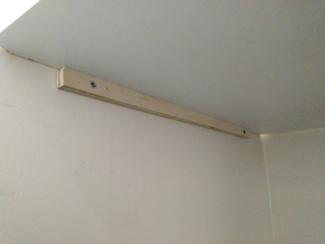
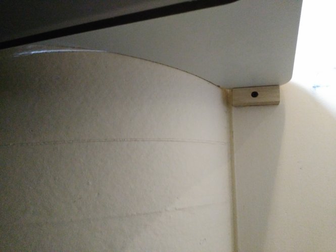
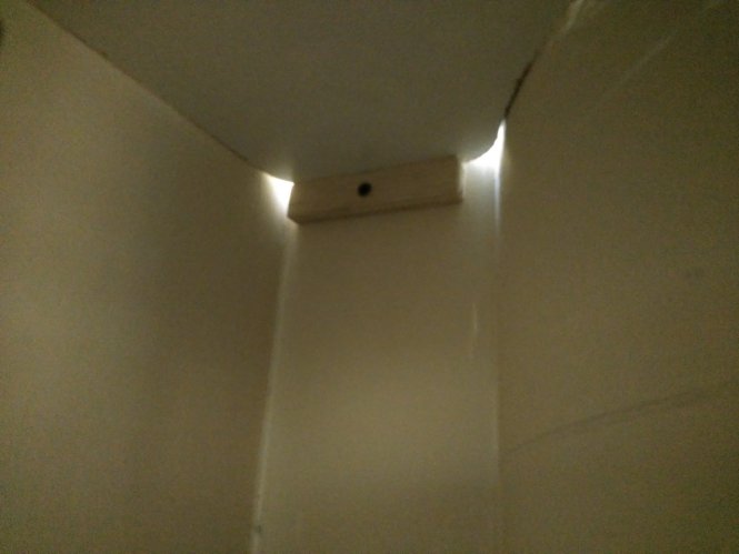
When I started this project, I also intended to design the a support structure for the tabletop. This design challenge, however, was quickly resolved and eliminated thanks to Professor Bove's suggestion of simply placing the tabletop on top of the existing table. This also solved the problem of what to do with the existing table after installing this new one. I placed the new tabletop on top of the smaller table as per the suggestion. Then, I attached small blocks of wood to the wall for added support on the edges of the tabletop. I first hot-glued those pieces to the wall to maintain them in a fixed position, and once the hot-glue had hardened, I bolted the blocks to the wall for better stability.
Finishing
I sanded off the edges of the tabletop and some scratches and other undersirable features from the top surfaces.
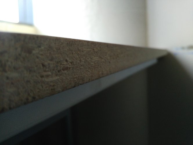
I then purchased melanine iron-on edging from Lowes and applied it to the front edge of the tabletop using an iron. This process took far longer than expected - several hours. I first had to remove the tabletop from its position and place it vertically. Then I secured the melamine with a masking tape along the edge, and began ironing it very slowly, while keeping a wet cloth between the melamine and the iron. The ironing process took about one hour to complete. After the ironing, I sanded off the edges of the edging to make them even with the surface. Finally, with a fine grit sandpaper, I sanded the edges just enough that they are not sharp to the touch.