Week 6: Molding and Casting
Overview
This week, I had to design a 3D mold, machine it, and cast parts from it. I wanted to make something that would serve a real purpose and not be merely an artistic piece. Moreover, I wanted my design to consist of more than one part. Thus, I chose to make a caster assembly. The wheel of the caster was made using the molding and casting process, and the remaining parts of the assembly were 3D printed. The process I followed to make the 2 part mold and then cast the wheel consisted of the following major steps:
- Make a 3D model of the part to created.
- Split the part model into 2 CNC-machinable components.
- Design a 2-part positive mold for each of the 2 components.
- Add "inverted tabs" to the positive mold, to ensure that the 2 parts of the negative mold will be properly aligned during the casting process.
- Add an "inverted hole" to the positive mold, such that the negatvie mold will have a hole for pouring material into it.
- Add a small "inverted hole" to the positive mold, such that the negative mold will have a hole for air to come out when you are pouring the material
- Machine the 2-part positive mold on eithet the Desktop ShopBot or the Modella.
- Fill with OOMOO® Silicone Rubber each part of the positive mold to create the 2-part negative mold.
- Fill the 2-part negative mold with Hydrostone or Drystone to cast the desired part.
- Sand off any undesirable surface features to achieve the desired finishing.
Making the 3D model
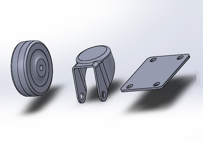
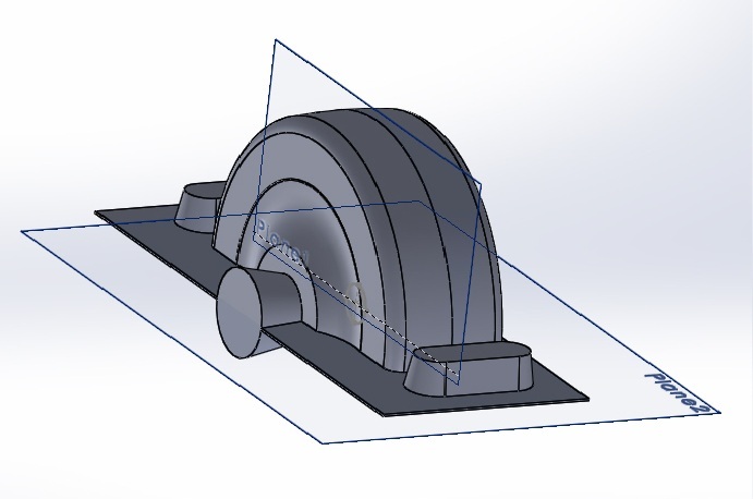
I based my caster wheel design on this model from GrabCad. Since the GrabCad model came as a part file rather than assembly, I first had to learn how to separate the different components of the model in SolidWorks. Hence I learned about and mastered the SolidWorks split features, and was able to separate the model into three parts as shown below.
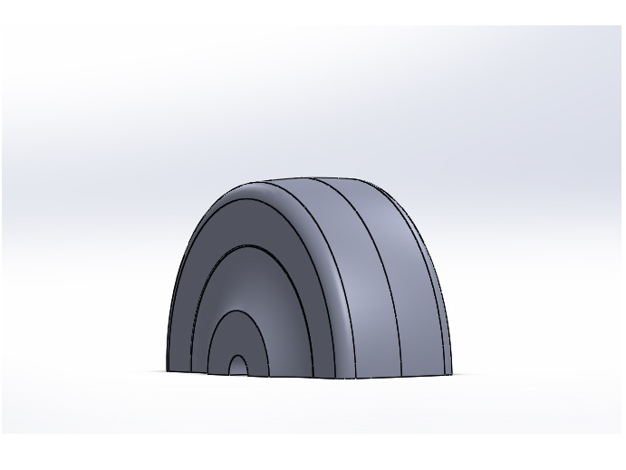
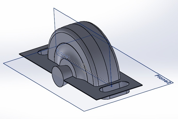
The wheel was the part I wanted to mold and cast, but because of its geometry, and surface characteristics, I needed to use a 2-part mold process. Thus, I first had to split the wheel into 2 identcal pieces. The obvious choice was to split the wheel along plane of the circle as it is normally done. However, I decided to be explorative this time and make the nonintuitive choice. I wanted to see what would happen if I were to split the wheel along the plane parallel to the rotational axis. I was curious to see whether this choice would work or not.
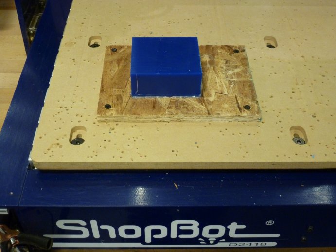
Onece the 2-part mold models were designed I milled them out of wax using on the Desktop ShopBot. I hotglued a block of wax to a board, and then I mounted the board to the sacrificial layer of the Desktop shopbot with four screws.
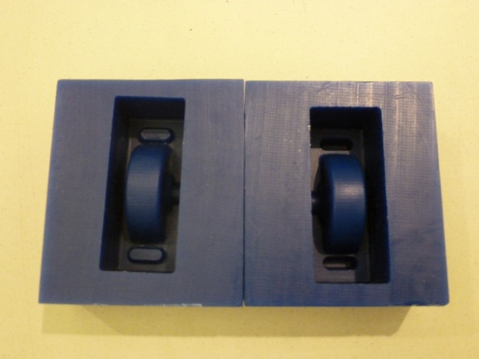
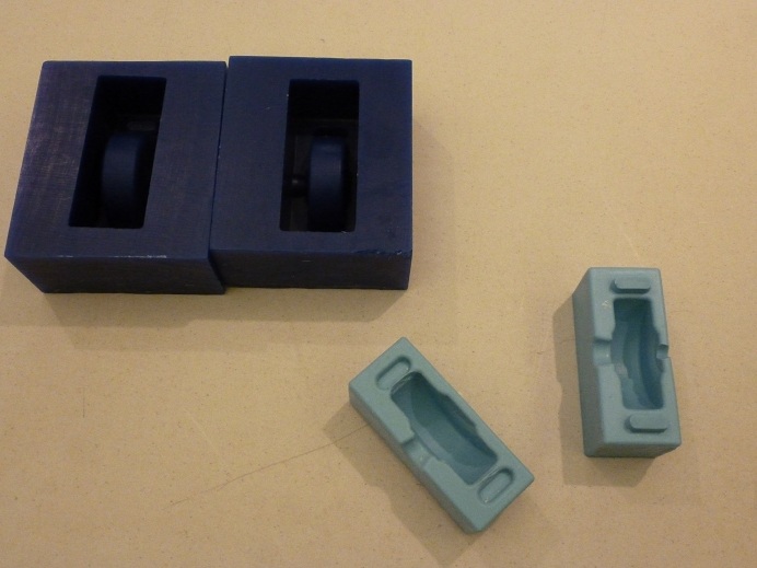
And here are the 2 mold pieces after the milling:
Next, I filled the molds with OOMOO and placed them in the vacuum chamber until air bubbles trapped in the material had escaped. Then I left the OOMOO cure overnight.
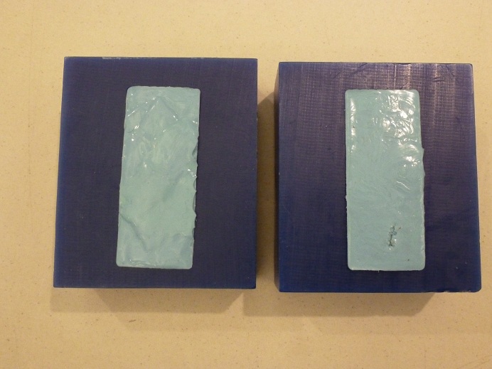
After a night of curing, the negative molds were ready.
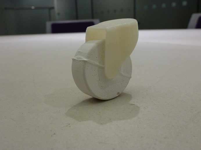
I then poured hydrostone into the 2 piece negative mold and let that cure overnight as well.
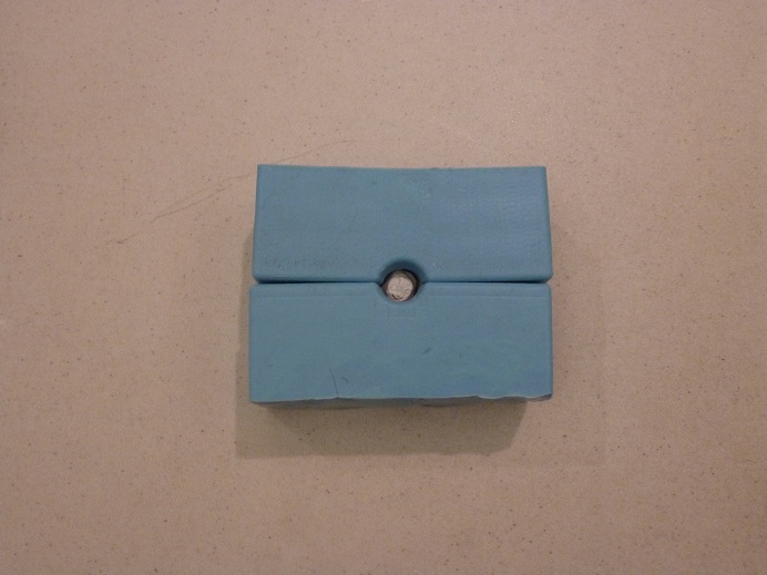
And here is the final result.