Week 4: Make Something Big
Objectives
This week, we had a very brief assignment: "Make something big".
Making Something Big
I have always been interested to make things on a CNC Machine. And this opportunity finally arrived. There were many things I wanted to build, so for me the problem was choosing which one of those should I make. I ultimately decided not to make "something big" but to make something smaller that can be used to make "almost anything big"
Nealy all furniture sold in stores is designed with a very specific uni-functinal purpose. If one needs say a desk or a bookshelf, they have to go and buy the very specific item they need. No only that, but they have to restrict themselves to a very specific size, color, design, and other attributes of this very specific item that they need. This puts too great of a restriction on the buyer, because they have to know exactly what they need, and moreover, the exact furniture that they need must be available for sale. If the furniture that the user purchaseses is not exactly what they want, or if they decide that they no longer like it, then the only options are to either trash that furniture and replace it, or to live with it. Both of those options aren't acceptable because the former creates pollution and results in a waste of natural resources, and the latter leaves an unhappy user. I wanted to solve this problem. Thus I thought about the idea of furniture made out of components that can be assembled into nearly anything - analoguos to Lego. That would trastically reduce pollution and conserve natural resources. A customer would have the option to purchase building blocks and then simply assemble the furniture that they envision and build it according to their specific tastes, needs, and preferences. Moreover, after they become tired of a particular furniture piece, the user can just disassemble that furniture and use the building blocks to build something new and different.
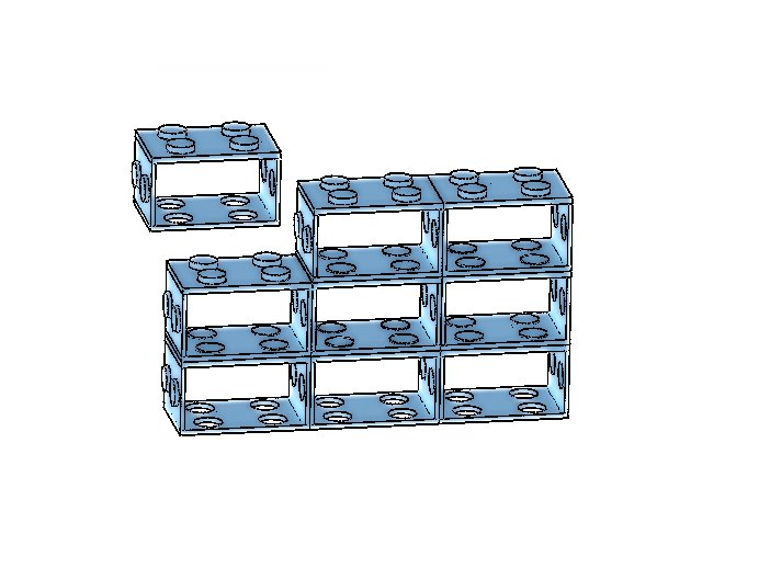
I spent a long time time thinking about how to make furniture modulal, and about how to make building blocks that can be securely attached to other building blocks. After considering several kinds of joints and making dozens of sketches, I ultimately desicded to make the assembly mechanism similar to the assembly of Lego blocks. But even then, there are still several options to consider: should the bumps be circular like Legos or some other geometric shape, how many pumps should there be per side, etc. Given the limitation of the Shopbot to make sharp internal corners, I chose not to make the bumps rectanular, and make them circular instead.
UPDATE:
My final project also involved making something big. I made an automated window that responds to the difference between internal and external temperature and humidity changes. For the mechanical part of the project, I made window frame and a replica or a glass window that attaches to that frame. I first made a model of the design in Solidworks, where I was able to specify the desired dimensions for all parts and to account for the exact thickness of each of the materials I was using. Pictures of the assembled Solidworks model are shown below, and the corresponding Solidworks assembly file is attached as well.
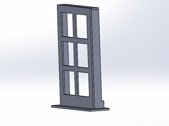
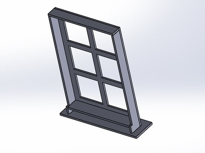 Solidworks Assembly
And here are all of the component peices layed out flat

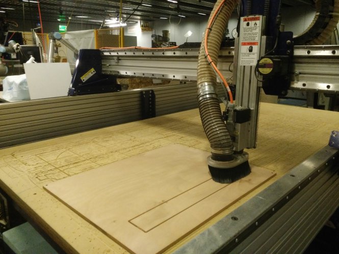
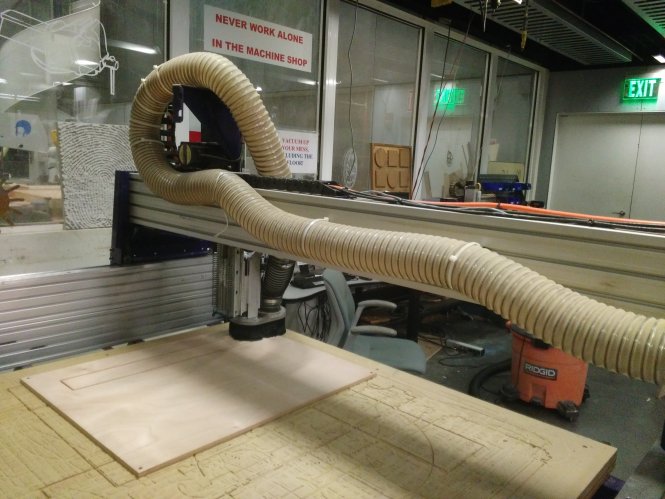
ShopBot Cutting
It requires a fair amount of training until one becomes comfortable using the ShopBot. The process of transformnig a SolidWorks model into actual pieces of wood is quite lengthy. Some excellent training tutorials can be found on YouTube which cover all of the details.
Place the wood on the bed of the shopbot and aligh so that it is parallel with the axes.
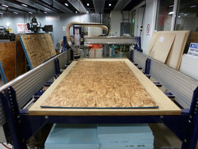
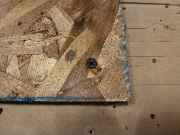
Secure the wood by material on the bed with screws at the corners and on the edges if necessary. Position the screws as close to the edge as possible. Make sure that the screws are placed in such a way that they won't interfere with the path of the endmill.
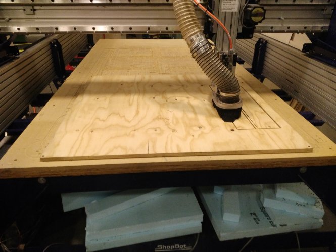
Set the zero points for x,y,and z on the shopbot. NOTE: The ShopBot at the Media Lab is oriented in such a way that when you are standing at the location of the computer, the origing is at the bottom right corner, and the x-axis is the vertical axis, y-axis is the horizontal axis! Move the head of the shopbot to the bottom left corner of the material using your keyboard's arrow keys, and then set that point to be the x=0, y=0 point. Then move the head somewhere over the middle of the material in order to zero the z-axis. This is performed in an automated way. After you have moved the head of the ShopBot to the desired position, take the metal plate and place it right under the endmill. Once the plate is in position, hit the Set Z Zero button on the toolbar in the software and this will automatically move the head down until it touches the plate and zet the z=0 point - where the software would automatically account for the thickness of the metal plate.
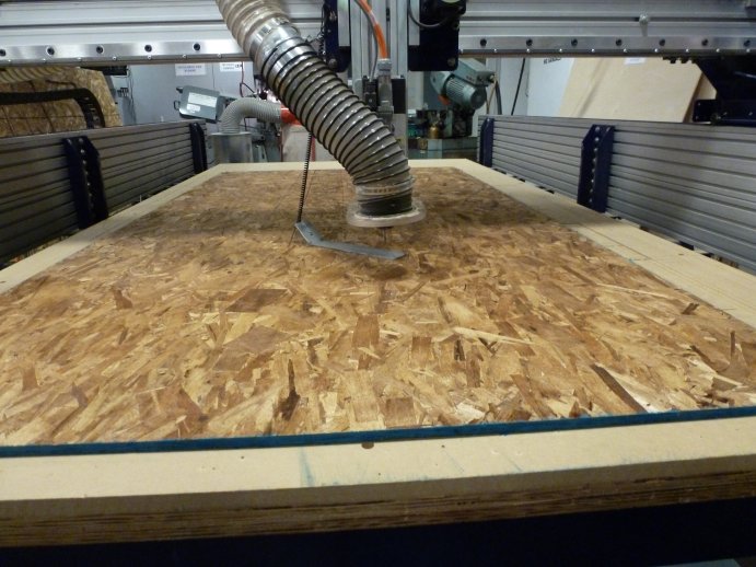
Put the metal plate back in its place and you are ready to begin cutting.
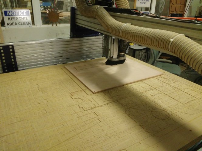
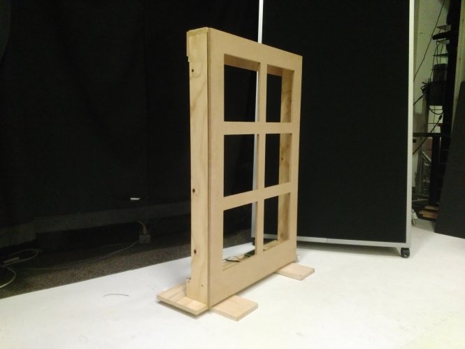
Here is the final result of cutting the pieces required for assembly of the frame
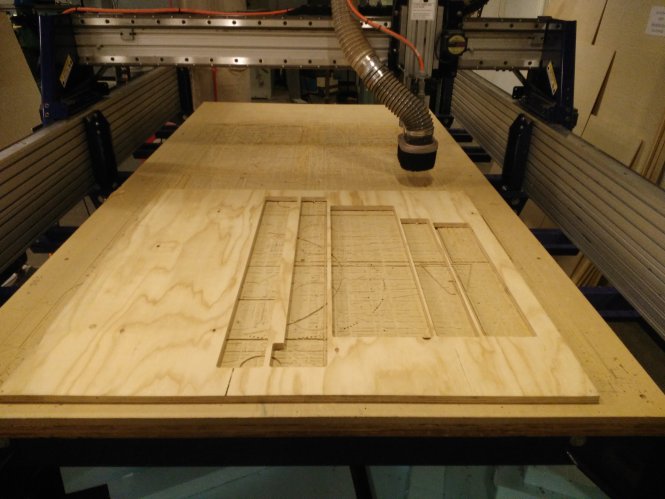
And here is the cut of the window that attaches to the frame.
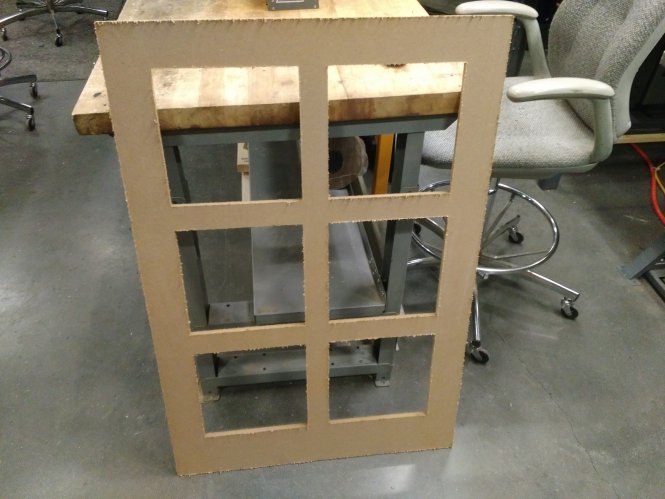
After I assembled the pieces, the design was not very stable, because the part that represents the window was too heavy for the frame to hold it without distorting the frame. Therefore, I had to cut a few additional pieces for support and attache them to the design.
The Final Result: