Week 9: Input Devices
Overview
For this week, the objective was to take a reading using an input device connected to a microcontroller. I wanted to do something more challenging, and integrate an input device and an output device into a complete project, where the output device is controlled by the input device talking to the microcontroller. In particular, I was interested in using a servo motor for displaying the data captured by some sensor. The options I consired for the sensor were a thermistor and a hall effect sensor. After some thought, I chose to make a magnetic field indicator consisting of a hall effect sensor serving as my input device and a servo motor serving as my output device / display.
Designing a New PCB
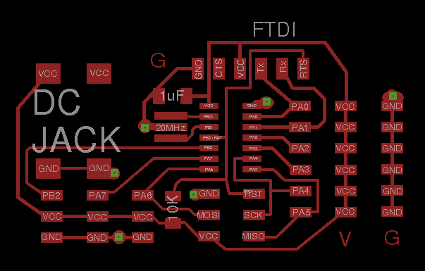
During the prevous week, I made a universal Arduino-like board based on the ATTiny44, and this was the board I was planning to use this week. However, I realized that I could make an improment to my universal board, by adding a an additional column of VCC headers on the right-hand-side of the board. In the previous iteration of the board, I only had a column of GND headers and a column of I/O pins. The limitations of that design, however were that a servo motor could not be directly attached to the pins on that side of the board. In this new version of the board, a servo motor could directly be attached to the board and to any of the I/O pins. Moreover, I also made some additional improvements to the routing of the traces, and I made the bottom side of the board a ground plane.
Addiging a Hall-Effect Sensor
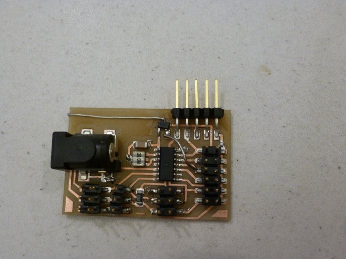
It was only after I had fabricated my universal board when I began looking for a hall-effect sensor to attach to the pins. I was surprised to find that the sensor we had was surface mount and incredibly small. That meant that in order to connect it to my board, I was going to have to design a simple PCB for the hall effect sensor and mill it. However because the milling machines were occupied by other students, and because I was running short on time, I decided to proceed with the intended project and try attaching the sensor wihtout mounting it on its own PCB. My first attempt was to solder wires to the pads of the sensor. That did not work, however because the pads we incredibly thin and fragile. Then I abandoned that approach as well and decided to just solder the sensor directly to one of the traces on the board. Because this was a risky job as far as the board traces were concerned, I did it on my the old universal board from last week. It went better than expected, as shown in the picture below.
Programming and Testing
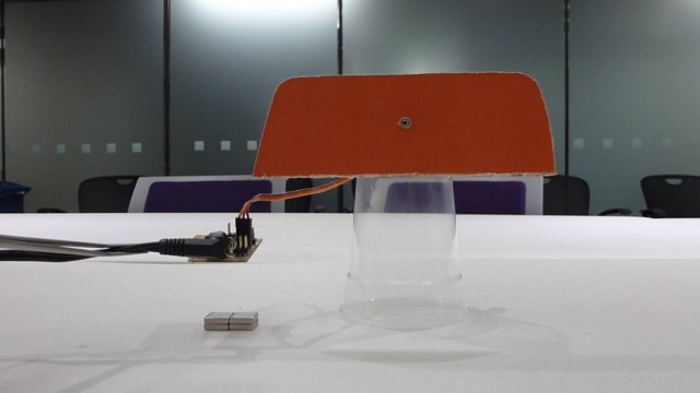
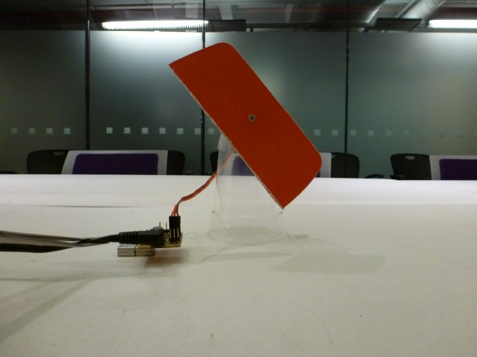
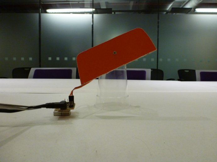
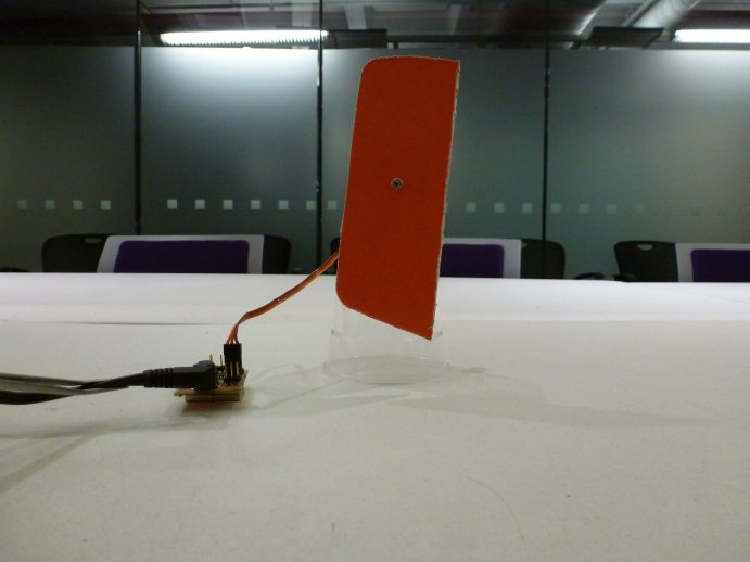
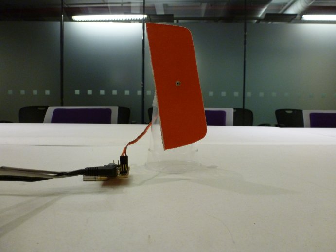
I wrote a simple program to test that my hall-effect sensor, and after confirming that it was sorking as expected, I prodeced and connected the servo motor. Then I modified my code, such that the angle of the servo would be a function of the analog input received on the pin to which the sensor was attache. The images below show how the system works. There are 2 magnets positioned on the table next to one another, where one magnet has its North pole facing up and the other its South pole up. As I move the sensor / board close to one of the magnets, the servo - to which a piece of red cardb oard is attached - swings in one direction, by an amount proportional to the rading coming from the sensor. As I move the sensor away from the magnet, the servo goes back to its normal position. If I posiiton the sensor near the other magnet, then the servo moves in the other direction. Finally, when I place the sensor right on top of a magnet the servo moves to its maximum position of approximately +90 degrees for the case of one magnet and apprxomately -90 degrees for the case of the other magnet.