1. Modeling
After I finished with sketching out a starting plan, I opened SketchUp to begin modeling the desk. After I seeing a demo of a fully armed and operational battlestation laser cutter in the GSD Fab Lab, and realized the amazing precision of CNC machinery, I felt inspired to incorporate greater complexity into my design using curves and more complex interlocking shapes.
Although I had worked assiduously on my rough sketch of my design, I was surprised how unshackled I felt working within Sketchup to improve and add complexity to the design. To me, this is the real benefit of CAD software - it's not simply a tool which allows you to model your ideas, but also a tool which enhances the degree of detail you can put into a design, unlocking a level of planning and creativity that is less accessible through pen-and-paper sketching.
|
|
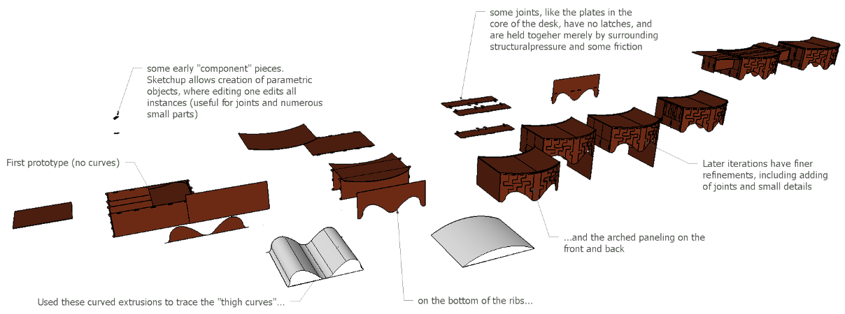
Design progression for desk. Click to enlarge.
|
|
Design Elements
I general, I tried not to make the curves and added complexity "frivolous", but add to the ergonomic and functional design of the desk. Rather than a flat bottom, the panels and ribs are all cut in a curving pattern resembling a recurve bow, so that the desk can rest securely on the thighs without sliding laterally. The spacing and size of the curves were measured to fit my dimensions, but because the curves' depth is shallow the desk would likely fit most people.
An additional design element was to make the desk extendable. It seemed likely that in addition to holding one item (e.g. a laptop), users might want to have a notepad, book, or peripheral such as a mouse on the desk, which would require lateral expansion. I decided to go with a sort-of "drop-leaf" design, with load-bearing arms extending from the sides of the desk holding up additional panels. While it would have been cool to make these surfaces extend in fully-fledged form, this presented many design problems. If the arms and leaves were one piece, they would require their own dedicated volume within the desk, which would support the desk when collapsed but would cause it to weaken significantly when extended, because of the large empty volume they would leave behind. I decided instead to have each arm composed of 3 vertical ribs of cardboard, which would slide through slits in the sides of the desk, minimally compromising its integrity and requiring no extra volume, since they would fit between the supporting ribs of the desk. After extended, separate leaves are attached to the tops of the arms. I decided the most convenient place to store these leaves would be on top of the normal working surface of the desk. Each leaf covers half the surface of the desk. When extended, the surface area of the desk doubles.
As one final design element, I decided the best way to fit the desk to the body would be to make the front and back faces curved. When viewed from above, along the axial plane of the body, the desk is concave on the side proximal to the user, and convex on distal side. This accomplishes two things. It allows the desk to be pulled in closer to the body and fit more snugly around the user than a rectangular desk. Secondly, it prioritizes providing surface area "within reach" of the user - on a rectangular desk the corners would be farthest out of reach, and the closest portion of the desk would be a single point lying tangent to the curve of the body. In this design, the far corners are eliminated and more space is provided around the user along a curve of contact.
Because of the curve of the desk coupled with it's extendable arms, the exact specification of the curving faces was to resemble a sinusoidal wave. In collapsed form, the curve starts at the point of inflection, extends to the crest of the wave in the middle, and falls back to the point of inflection at the other end. When extended, the leaves on top of the desk are removed and flipped upside-down, which makes each leaf complete the path from the point of inflection at the edges of the desk down to the trough of the wave. When viewed in fully extended form, the desk's shape comprises of one full wavelength of the sinusoidal curve.
|
|
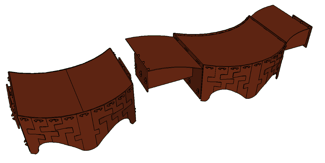
Final Design - in collapsed and extended form.
|
|
Using Sketchup
This next section is a basic primer on the functionality of Sketchup Make. It is meant to be a resource (and may eventually turn into a tutorial), and so feel free to skip it if that is not your aim. However, I will invoke some of this terminology in the next section when explaining the modeling process for the desk.
For this project I used Sketchup, the only 3D CAD software I had any previous experience with - and the free version at that (Sketchup Make), with only basic functions. It has a reputation as a simple program without a ton of features that you would find in Rhino or Solidworks (as far as I'm aware, it does not even have a command line), but with a geometric thinking and clever use of the limited (but versatile) tools it has, it can still be a very powerful tool. Especially for projects like this, where there are no complex 3D shapes (for the purposes of the laser cutter, all shapes will be basically very thin prisms).
For a quick overview of the basic features of Sketchup Make: the drawing tools include a line tool (straight and freehand), a shape tool (rectangle, circle, and equilateral polygons with n sides), and a curve tool (arc, 2 point, 3 point, pie section). Beyond that, use the push/pull tool to extrude 3D prisms from flat shapes or to create hollowed out features when "pushing" a shape into a 3D solid. There are also features to scale, rotate, create offset shapes and lines, and of course move components. Throw in a few simple controls for manipulating the view screen, a measuring tape, snap-to points and the ends and middles of lines and shapes, and some functions for moving and aligning parts to each other or along the x,y,z coordinate grid, and that's basically all of the functionality of Sketchup Make.
Now we come to a fundamental feature of Sketchup, and one that is far more interesting than the above: groups and components. This concerns how lines and surfaces can (and should) be joined into more complex shapes, and it seems to be a distinctive feature of Sketchup compared to Rhino (I cannot speak for Solidworks). How does it work? By default, all objects in Sketchup exist fully exploded - that is, made entirely of lines and planes. So for example, if you draw a square and then "push" it to make a cube, you will then create 6 square faces and 8 vertices, all of which are joined together. But if you want to move the cube, all of the faces and vertices must be selected. If some of these pieces are not selected and you try to move the cube, it will stretch and distort the shape (which does have its purposes). In order to make the cube into a single object which can be selected with one click, all the pieces need to be selected and then "grouped".
Groups can include any number of connected or unconnected surfaces and lines. But groups can also include other grouped objects. This has interesting implications. It means that groups can be nested within each other, and the user can create a virtually limitless number of groups, sub-groups, sub-sub-groups, etc. This allows for a great degree of control when designing complex objects with many separate modules. Groups can always be "opened" so their contents can be edited, and an entire group can also be modified at large using the tools above (including scale, rotate, etc).
Lastly, the component tool works just like the group tool, except that when specifying a component part, all of the future copies of that part will be tied together. (This is analogous to the "clone" function in Inkscape. This does not include rotation or positioning of the objects, but it does include all other design aspects. So if you have a two copies of the same component, and decide to scale one to make it larger, then all of the copies of that component will also scale up (in their same position and orientation). This feature, at its core, is a type of parametric design, a feature which native Rhino entirely lacks. It was particularly useful for this project when I designed some parts which were used over and over again, but which sometimes needed small adjustments based on testing and measurements.
Highlights from Modeling
The first part of the modeling process was making the basic desk I had drawn on paper. Already as I constructed it, I started to play with the curve tool to make a non-rectilinear desk design, a sort-of kidney-bean design that's common in desk design. Unlike the sketches, when making my model in Sketchup I needed be be specific about dimensions and absolute relationships between the pieces of the desk. This cropped up as a fundamental difference between designing with drawings and with CAD software. A detailed drawing can contain measurements and an implicit understanding of fit, but CAD forces you to become explicit, and badly thought-out measurements will become apparent. Another trade-off is that designing in CAD is a continuous process, while drawings are discrete and iterative. In CAD, designs can be continually improved, tweaked, and changed, which lends a "never finished" feeling to the design. In contrast, sketches usually have a final end point, and new ideas and features need to be sketched again in later drafts. This is not a clear-cut case of pro and con, but merely represents a trade-off in the design process.
Rather than outline the entire process of making the desk, I want to call attention to two specfic design elements which retrospectively got the most attention - if you are interested exploring the rest of the design, the models are freely available for download at the bottom of the page.
To achieve the "thigh curves" on the bottom of the desk, as well as the curvature on the front of the desk, I first plotted the curves I wanted to use and then extruded them as solid prisms to use as stencils in the design. In Rhino, a Boolean operation could be used, but basic Sketchup lacks these, and so this was my best option. This stencil approach was important for the thigh curves especially, because the inner ribbing is a single planar surface, while the front and back of the desk is an arc. Thus, the excisions made from the flat and angled pieces would necessarily have to differ in order to achieve the same shape for the thighs throughout the design. My solution was practical, if inelegant. I simply placed the stencil within the center of the model, and used the line tool to trace the area where the stencil intersected with the desk pieces. These tracings were composed of a series of straight lines rather than curves, but the segments were short enough so the difference would not be noticeable to anyone but the keenest observer. After the lines were traced, I deleted the portions under the pseudo-curve, leaving only the portions above the stencil.
|
|
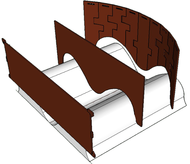
The stencil with three panels of the desk. The stencil is slightly offset down from "cutting" position.
|
|
A second design feature of interested was the arched paneling in the front and back of the desk. This design was my solution to achieving a closed, apparently curving surface without using flexures or kerfing. The modeling process was relatively straightforward. After designing the basic sinusoidal profile of the desk (outlined in the Design Elements section above), I used the tape measure tool to measure the length of the curves. Each was about 20 inches long. I decided to have an odd number of panels (so the middle one would lie tangent to the apex of the curve), and dividing it into 9 panels yielded a width for each panel of approximately 2 and 3/16 inches. I then used to rotate tool to align each of the 9 panels so they lay tangent to the curve of the desk. A wide slot was added at the top of each, along with hooks on the supporting layer of the desk to attach them to the frame.
I decided that this would not be enough to hold the panels steady, and so I added tabs and notches on the panels closer to their bases, which would keep them aligned and under greater constraint. The final effect was much more interesting and aesthetically pleasing than I had originally intended, but this should not belie the simplicity of designing these tabs. The primary consideration was that the notches needed to have enough clearance to allow the tabs to cross through them to overlay the adjacent panel. This was relatively trivial to account for, since the thickness of the cardboard was in the model. I simply needed to pick a starting height for each tab (which was done by using a second curved stencil, a single arch, to align where the bottom of each tab would be), and drew a 1" tall rectangle on the adjacent sides of both panels. On one panel, I used the push/pull tool to pull the tab enough so that it would pass above the panel, and conversely I pushed the rectangle on the adjacent panel to make a notch, until I could visually confirm that the notch was deep enough to avoid colliding with the tab. Again, relying on visual cues might not be the most elegant solution, but it was very simple to execute, and in the end very effective. I duplicated this procedure for every panel, except the panel which had the tab now got a notch, and the notched panels now got a tab. A fairly simple procedure, but very visually appealing and relatively robust. It seems like I might be able to re-use this in other designs when a sturdy curved surface is needed to be made from rigid, planar parts. In the end there were only 5 unique parts, since the front and back of the desk were exactly the same structure, within the arch only the middle panel lacked a mirrored partner.
|
|
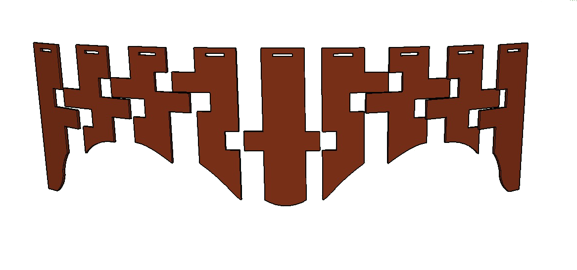
The full array of 9 panels. Slightly spaced to show extra clearance needed.
|
|
One last note on the parametric component feature of Sketchup. I did indeed use this tool when designing the various tabs and notches, so that minor changes could be reflected across the design. This was especially useful in the second prototype (outlined in the 3. Assembly section), when I a small forked fastener for nearly every joint of the desk, increasing the friction between the joined parts.
Go to next section: 2. Cutting
Download Schematics
