30 Nov 2016 · 2 min read
The assignment for this week was to write an application that interfaces with
an input or output device that we made. For this week, I decided to write a GUI
to control my RGB LED.
Embedded Code
First, I had to write embedded code that could let me control the RGB LED in an
interesting way. I wrote a clock interrupt-based PWM routine that let me
independently set the R, G, and B channels to one of 20 brightness values.
Next, I wrote code to take commands over serial to change the LED values. I
used a simple protocol, where a control message was contained in a single byte.
The upper 2 bits were used to set the color, and the lower 6 bits were used to
set the intensity. Decoding was as simple as:
color = input >> 6
value = input & 0x3f
There were some challenges with getting the serial input to work correctly.
After some debugging, I found that I needed to disable interrupts while reading
a byte in from serial (otherwise, the timing would get messed up by the LED
PWM).
My final code for my ATtiny44 is available here:
https://gist.github.com/a2e7e2bb7718dc1c2a4ddbdcc317898a.
GUI Code
Before writing the GUI, I wrote a simple test
program
to verify that communication over serial worked as expected.
After that, I used the TkInter library
to write a simple GUI in Python:
import serial
import time
from Tkinter import *

DEVICE = '/dev/ttyUSB0'
SPEED = '115200'
PWM_MAX = 20

def get_data(color, value):
    assert color in 'RGB'
    assert 0 <= value <= PWM_MAX
    cbit = 'RGB'.index(color)
    data = cbit << 6 | value
    return chr(data)

def write_color(ser, color, value):
    data = get_data(color, value)
    ser.write(data)

def main():
    ser = serial.Serial(DEVICE, SPEED)
    ser.setDTR()
    ser.flushInput()
    ser.flushOutput()

    master = Tk()
    master.wm_title('LED Control')
    def set_color(color):
        def setter(value):
            value = int(value)
            write_color(ser, color, value)
        return setter
    def add_scale(color, label):
        scale = Scale(
            master,
            from_=0,
            to=PWM_MAX,
            orient=HORIZONTAL,
            command=set_color(color),
            label=label
        )
        scale.pack()
    add_scale('R', 'Red')
    add_scale('G', 'Green')
    add_scale('B', 'Blue')
    mainloop()

if __name__ == '__main__':
    main()
Result
The interface looks like this:
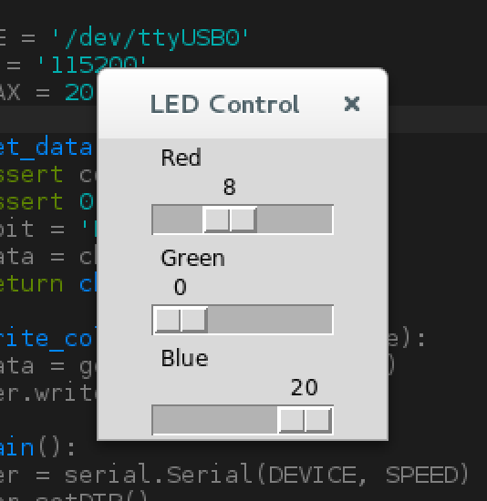
Dragging the sliders changes LED values in real time:
23 Nov 2016 · 3 min read
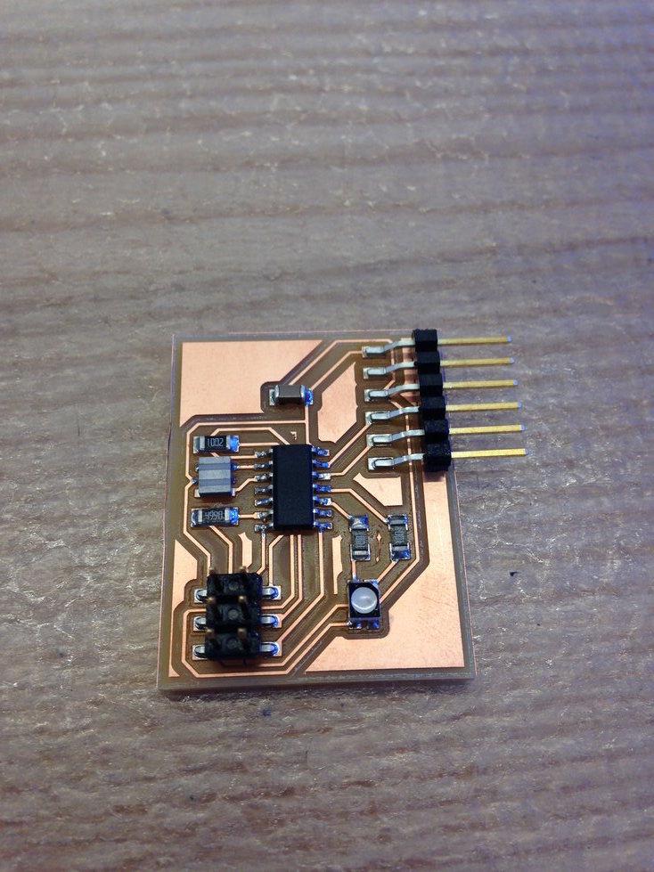
This week’s assignment was to design and fabricate a microcontroller with an
output device. This week, I decided to keep it simple and design a board with
an RGB
LED.
I also included an FTDI port on the board so that I could later program the
board to interface with a computer over USB.
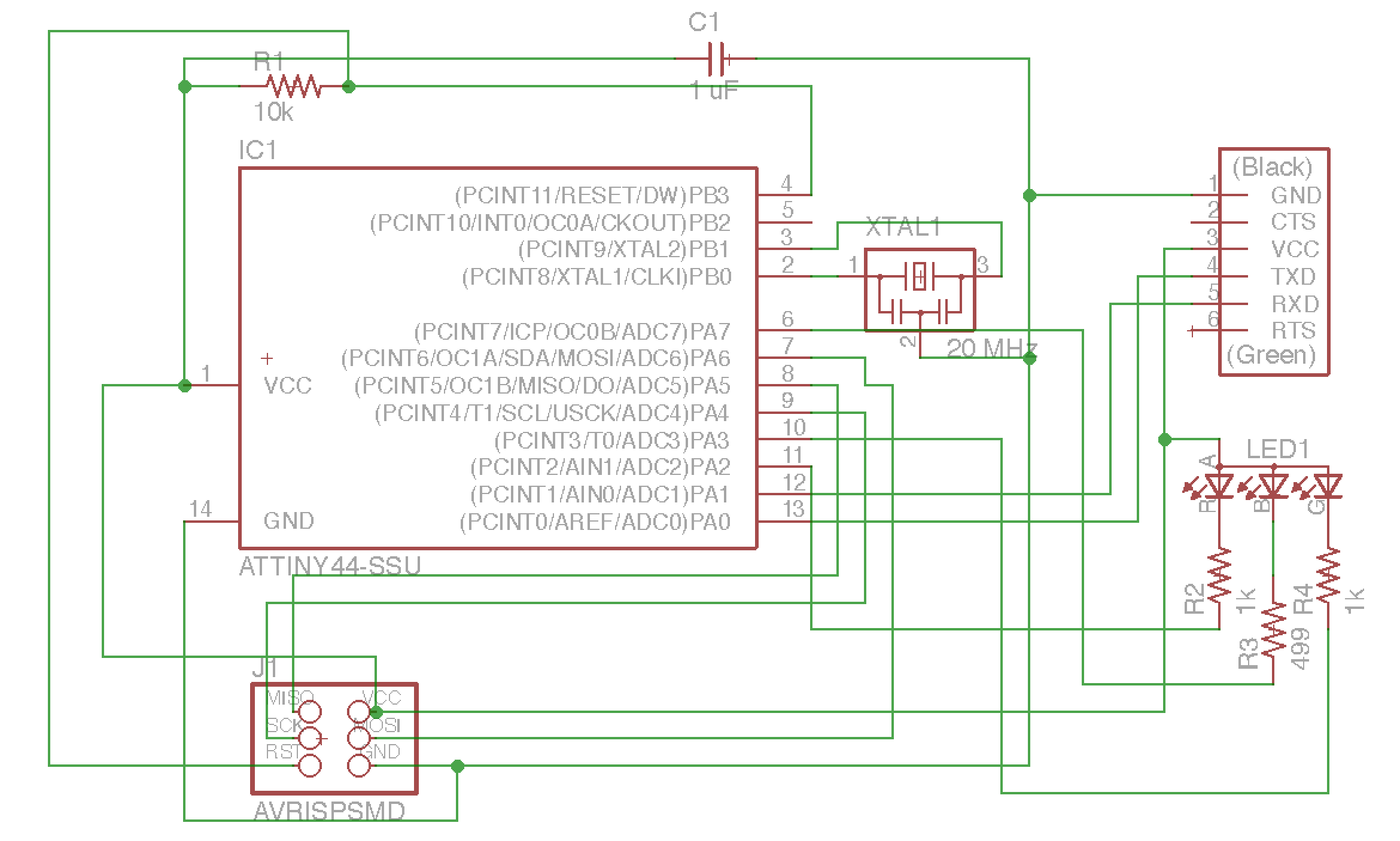
Design
After designing a couple PCBs over the last couple weeks, I’ve gotten fairly
comfortable using EAGLE. Here’s my schematic and board design:
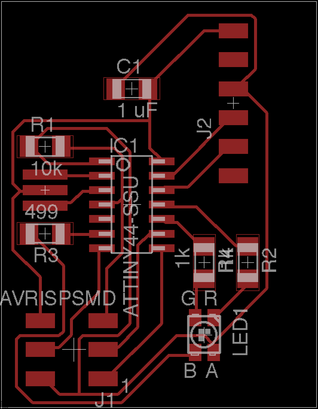
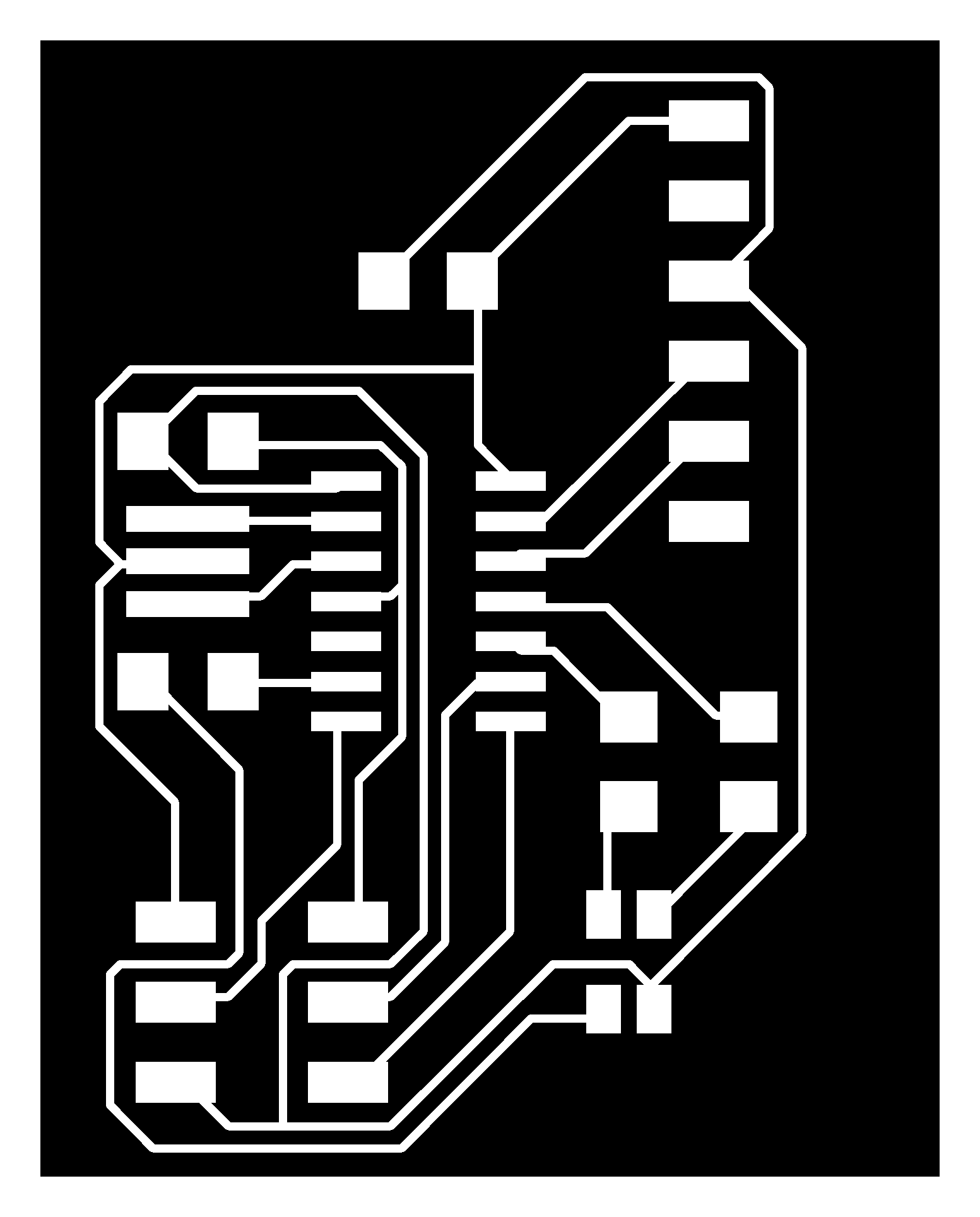
Here’s my outline and
traces.
Production
Following the same procedures as in previous weeks, I milled my board on the
Roland SRM-20. This week, I decided to use solder paste when stuffing my board.
The procedure was really simple — I carefully put solder paste on pads,
placed components, and then I used a heat gun to solder everything. It took
about ten minutes to complete the entire job. Here’s the end result:
Software
For now, I’m not using the FTDI port on the board. I wrote some software that
cycles through colors on the RGB LED, going through red, green, blue, cyan,
magenta, yellow, and white. In the future, I might experiment with using
software PWM to get more colors.
Here’s the code I wrote:
// blinking LED
//
// set lfuse to 0x5E for 20 MHz xtal
//
// Anish Athalye

#define LEDPORT (PORTA)
#define LED_R (PA2)
#define LED_G (PA3)
#define LED_B (PA7)
#define SETB(byte, bit) (byte |= (1 << bit))
#define CLRB(byte, bit) (byte &= (~ (1 << bit)))
#define ASSIGNB(test, byte, bit) do { if (test) SETB(byte, bit); else CLRB(byte, bit); } while (0);

#include <avr/io.h>
#include <util/delay.h>

int main(void)
{
    // set clock divider to /1
    CLKPR = (1 << CLKPCE);
    CLKPR = (0 << CLKPS3) | (0 << CLKPS2) | (0 << CLKPS1) | (0 << CLKPS0);

    // set to output port
    DDRA |= (1 << LED_R | 1 << LED_G | 1 << LED_B);

    // cycle through colors
    while (1)
    {
        for (int red = 0; red <= 1; red++) {
            for (int green = 0; green <= 1; green++) {
                for (int blue = 0; blue <= 1; blue++) {
                    ASSIGNB(red, LEDPORT, LED_R);
                    ASSIGNB(green, LEDPORT, LED_G);
                    ASSIGNB(blue, LEDPORT, LED_B);
                    _delay_ms(1000); // wait for a second
                }
            }
        }
    }
}
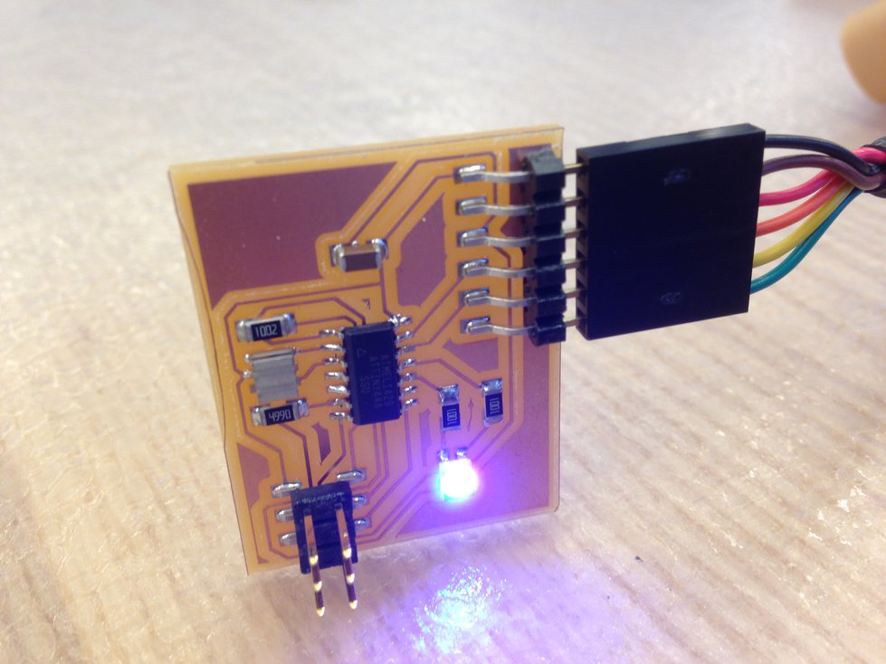
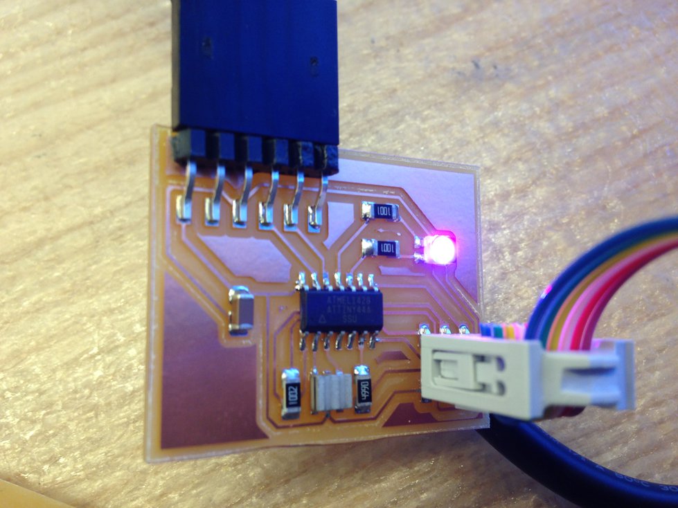
Result
Here’s a picture taken while running the program:
16 Nov 2016 · 5 min read
This week’s assignment was to make a 3D mold and produce a fiber composite part
in it out of burlap and epoxy.
So far, I had been using Fusion 360 for most of my 3D modeling work in this
class. I saw this week’s assignment as a good opportunity to get some exposure
to a different tool. I decided to use Rhino for
this week’s assignment. To help familiarize myself with the software, I went
through the “Getting Started” tutorial on the Rhino
website.
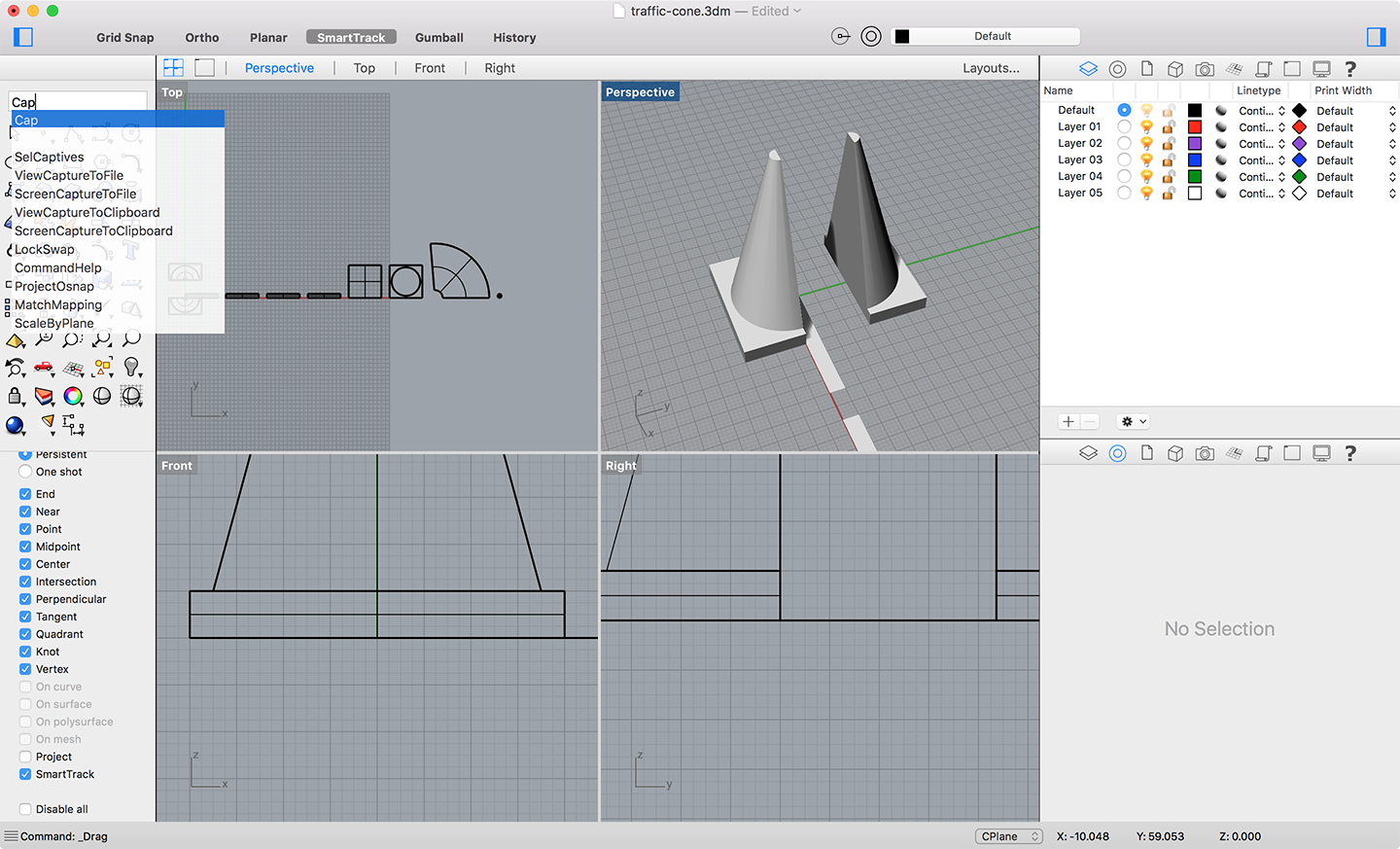
Design
I decided to design a traffic cone. Basically, doing what I did a few weeks
ago,
but on a much larger scale:
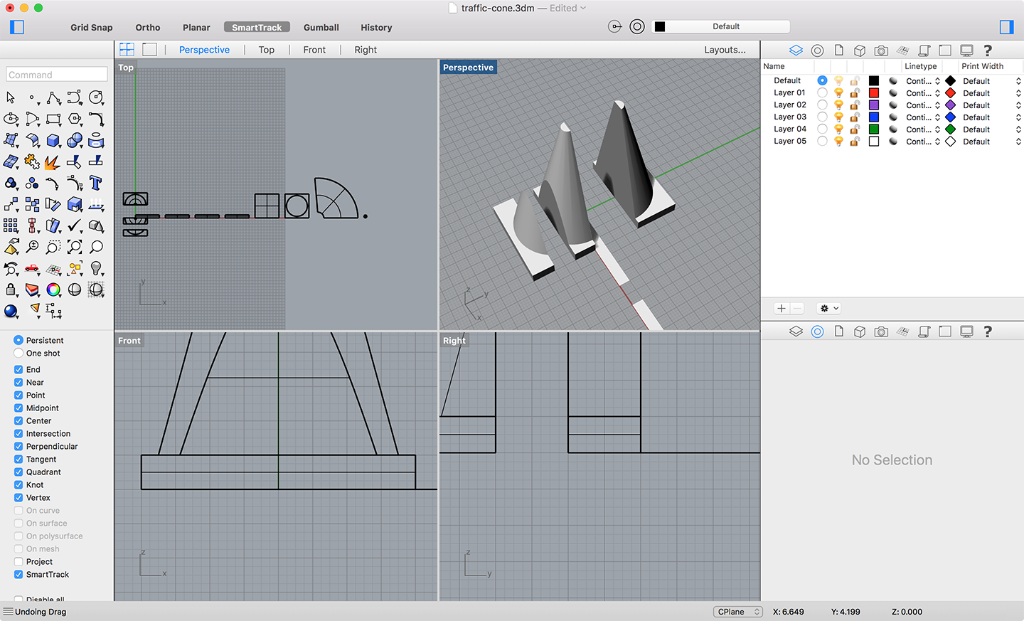
Designing the cone was pretty straightforward. After completing the basic
design, I unrolled the mesh to produce 2D shapes that could be laser cut. I
also split the cone into shapes that could be milled on a 2.5-axis milling
machine. I ended up having to do some more slicing so that the depth of each
slice would not exceed the total depth of the material I was milling (2
inches):
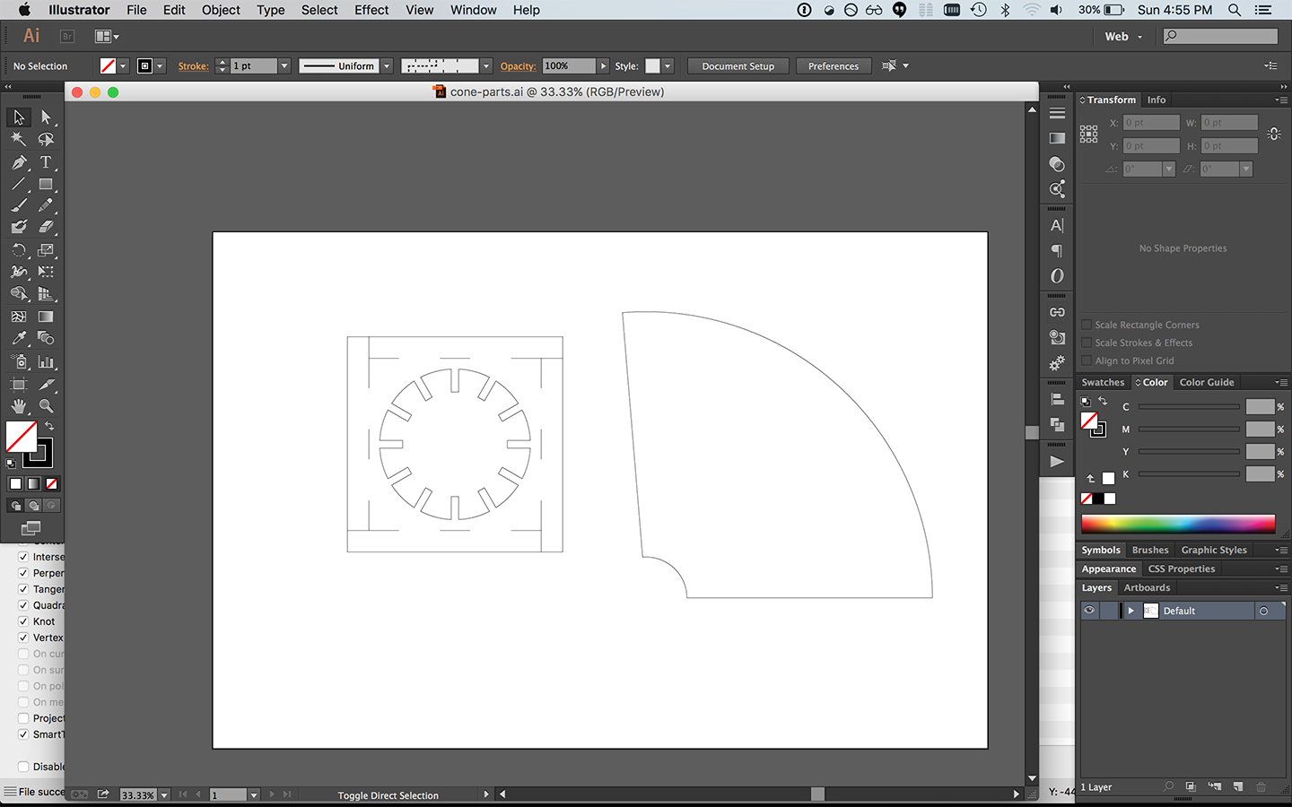
On the 2D side of things, I arranged my parts in Illustrator such that I would
have two parts — the platform and the cone itself. I added some extra cuts
for making it easier to fold parts, and I also added some extra material as
support material:
Production
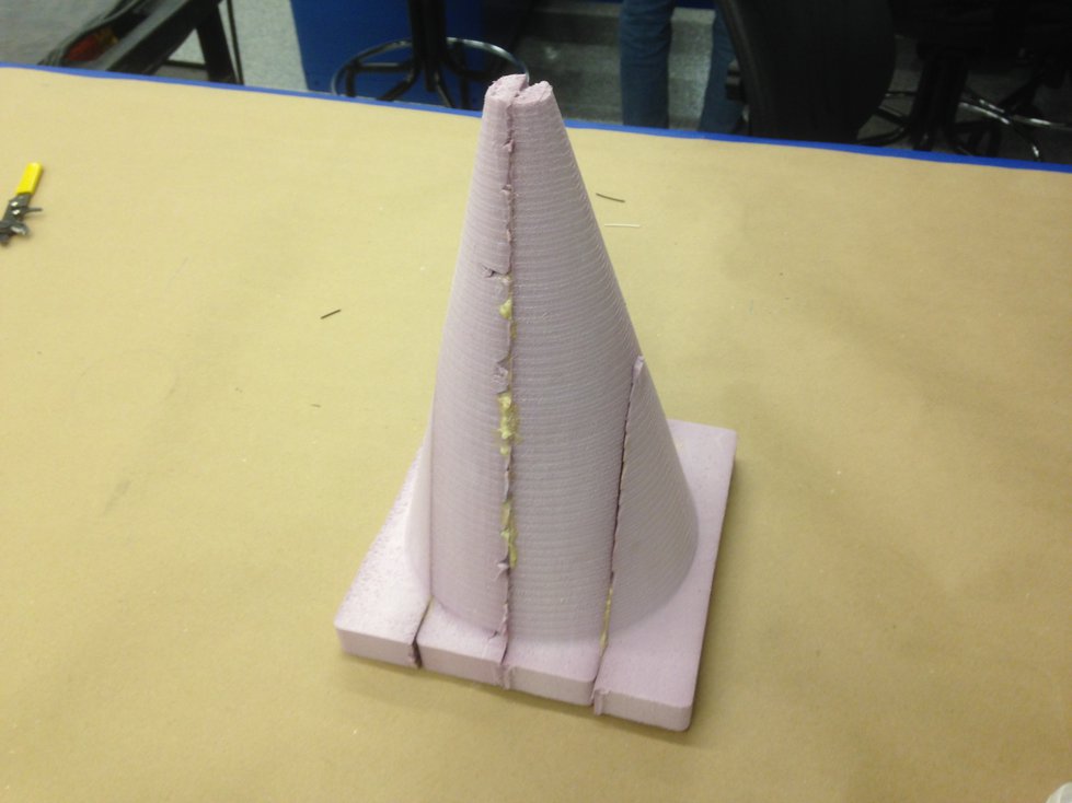
Foam Model
First, I made a foam model out of 2” thick building insulation foam. My piece
was approximately 8” x 8” x 12”, so this I needed to produce my piece in 4
parts. I used VCarve Pro to
design toolpaths for the CNC Shark. During this process, I added a couple tabs
to the piece so it would stay in place during the job. I used a 0.5” flat end
mill for the job. I chose this particular bit mainly because the bit was deep
enough to cut 2” into the model without having the collet strike the surface of
the material.
In terms of other settings, I had a pass depth of 0.4 inches, a stepover of 0.1
inches, spindle speed of 6000 rpm, feed rate of 200 inches per minute, and a
plunge rate of 60 inches per minute.
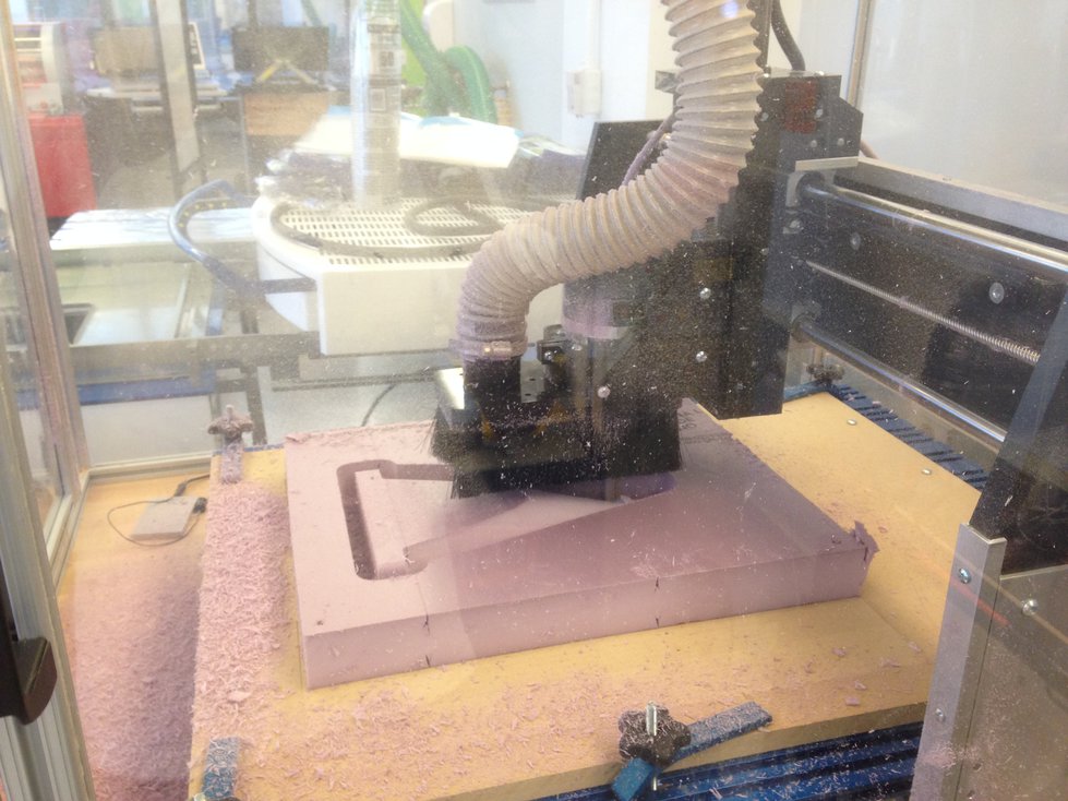
Here’s a photo of one job in progress:
The CNC jobs went mostly according to plan, but there was one strange issue I
had with the machine. During my finish cuts, there were times where the CNC
mill would lose its Z positioning — it was always in the positive direction,
so it would be cutting a few inches higher than it should have been. When the
mill lost its Z positioning, it didn’t lose its X or Y positioning. So my
pieces were never damaged as a result of this, but my jobs sometimes had to be
restarted. After this happened a couple times, I figured out the cause of the
issue. In some parts of my job, the end effector would go from Z = -2 inches to
Z = 0 inches in a single G-code instruction. Because the feed rate was pretty
high, the machine would move really quickly, and it would overshoot and lose
its Z position in the process. A workaround was to reduce the movement speed
for rapid movements in the Z direction — after making this change, I didn’t
have problems with the machine losing its positioning.
My 4 machining jobs took a total of approximately 3 hours of actual machine
time. Counting the time I spent setting up the toolpaths, setting up the
machine, and debugging, it took a total of about 5 hours to produce the parts.
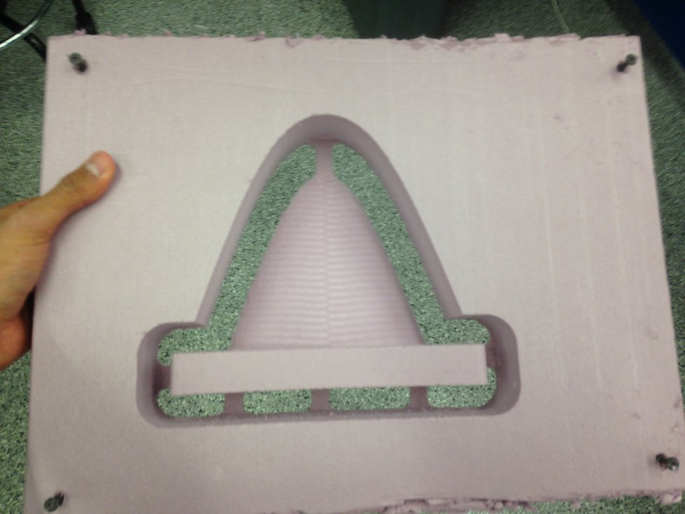
Here’s what a single part looked like as it came out of the machine:
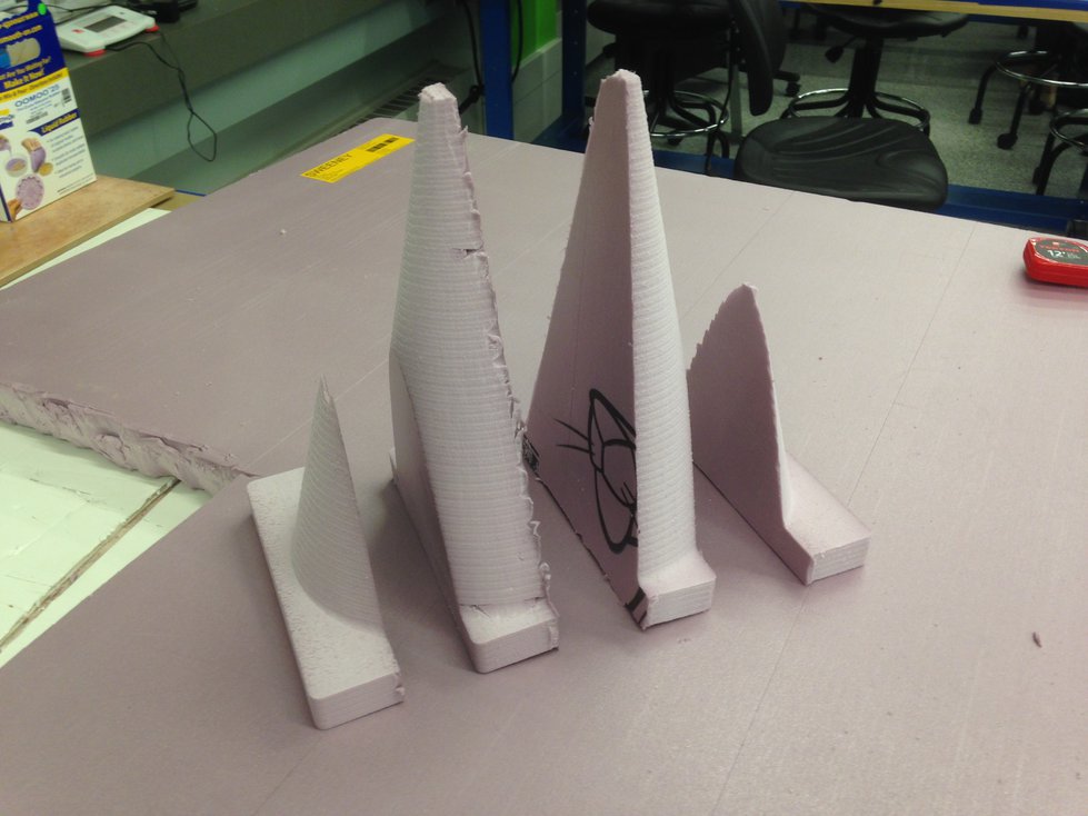
And here are the completed slices of the cone:
I used Gorilla Glue to assemble the slices into a single piece. Here’s the
result after gluing and waiting 24 hours for a full cure:
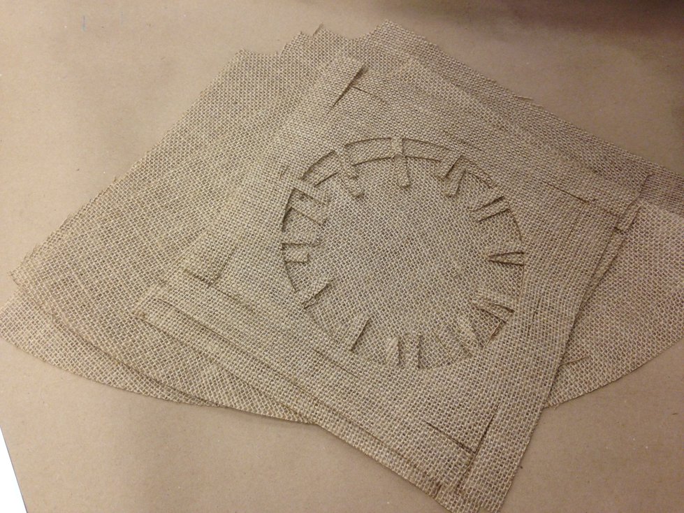
Burlap Surfaces
Next, I cut my 2D surfaces out of fiber using the Universal PLS6.75 laser
cutter. It took several test cuts to get the settings just right, but
eventually, I found settings that cut cleanly through the material. I used the
materials database, selected “Denim” with a thickness of 0.035”, and added a
“+50%” for vector cutting. Here’s the result of cutting 3 cone surfaces and 2
bottom surfaces (for layering):
Composite
Finally, I was ready to produce the composite, using burlap as my fiber and
Entropy Resins Super Sap
One as my resin.
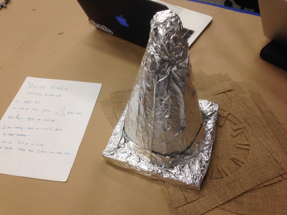
I started out by covering my foam with aluminum foil and then spraying that
with mold release:
After that, I mixed epoxy, soaked my laser-cut burlap with the epoxy, and
stacked the parts on my aluminum-covered cone. I used a total of 5 layers: a
cone surface, then a base, then another cone surface, then another base, and
then a final cone surface. I covered that with perforated film, covered that
with breather material, and then placed that inside a vacuum bag. I pulled a
vacuum with the ShopVac, and the result looked like this:
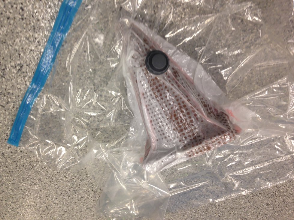
I was concerned that the bag wouldn’t conform to the shape of the cone, but it
seemed to work reasonably well around the cone as well as the base.
Result
Here’s the final result:
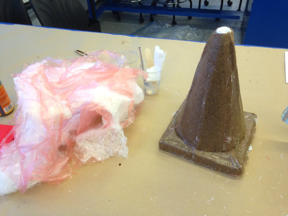
Even though I used a generous amount of mold release on the aluminum foil, the
inner foam mold proved to be difficult to remove from the completed piece.
Currently, most of the foam is still inside the composite.