Week 4 - Electronic
How to Make (Almost) Anything - Manolis Zampetakis
Design
For this week we decided to just get familiar with the design tools proposed in the class and we used the Eagle to design the circuit that we wanted with the addition of one LED and one button. The button and the LED are placed in different ports of the controller. The idea is that we will get a 5V signal from the button that when it is activated it will do something with the LED. Maybe it switch the state of the LED from open to close and vice versa.
The problem was that the autorouter of Eagle does not work well! There are times that it is clear what the correct route should be in order to avoid two layers and the autorouter cannot find it. This is pretty strange because the planarity testing in graphs is a problem that can be solved very fast and with small modifications there should be a more clever algorithm to do the routing. One very interesting attempt for small circuits was made by Christos Tzamos when he developed the tool PCB Designer. Although the algorithm that this tools runs is not sofisticated at all, it performs much better than the algorithm that Eagle uses! Later in the course we will contribute in extending, debugging and increasing the performance of this tool.
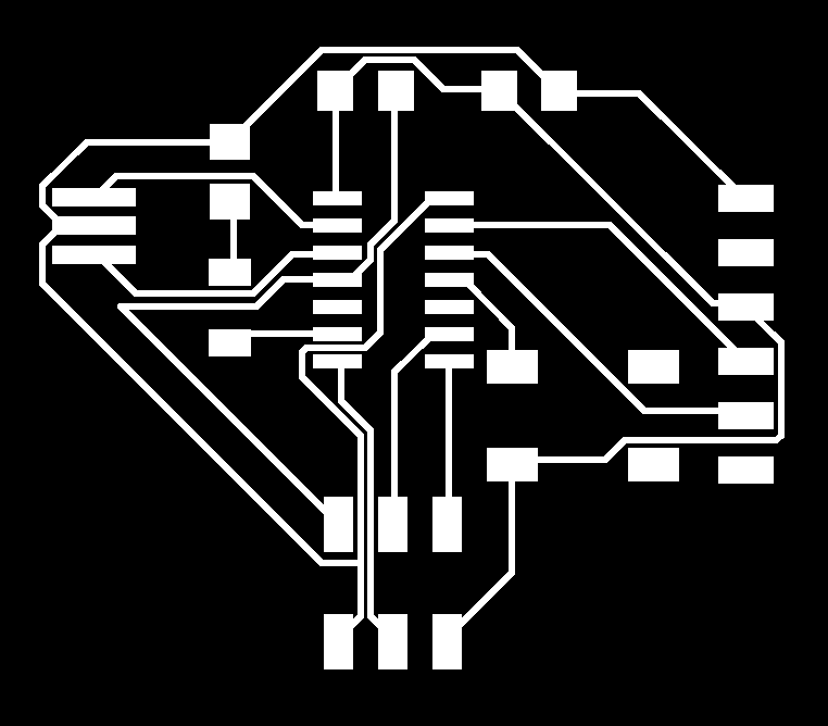
After some manual work at Eagle we got the following figures.
 |
 |
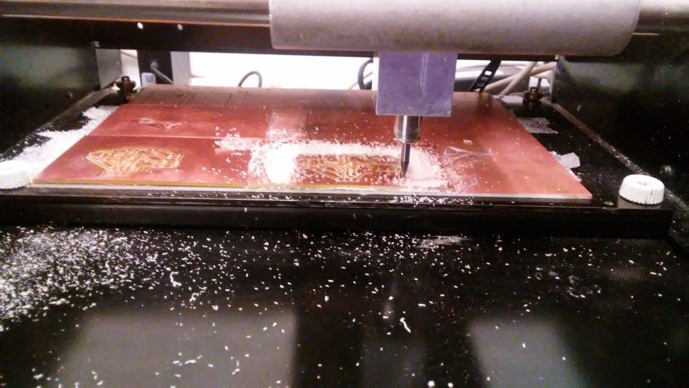
Milling Proccess
After designing the board we used the Roland machine to do the traces and cut the board. The problem was that the traces were very close as designed by Eagle and we had to do some edits on the picture in order to make it possible to be printed by the model machine. After these edits we succefully printed the board.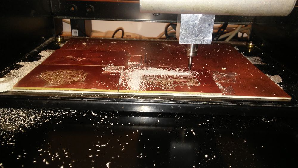 |
 |
Soldering
The soldering was very easy this time because of the experience that we had from the second week. We started with the big components first and everything was completed well.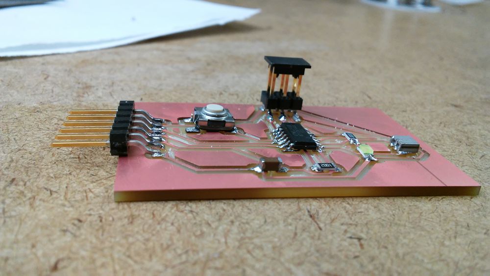 |
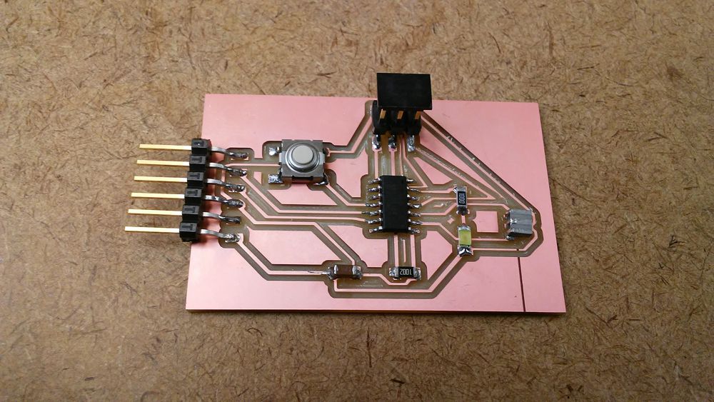 |
Lessons Learned
i. Don't use Eagle for the autorouting!
ii. Be careful with the empty space between the traces. They have to be large enough for the machine to print them.
iii. It is a good idea to start with the big components first in case something goes wrong and you need a new board.