Week 12: Interface Programming
assignment: write an application that interfaces with an input &/or output device that you made, comparing as many tool options as possible
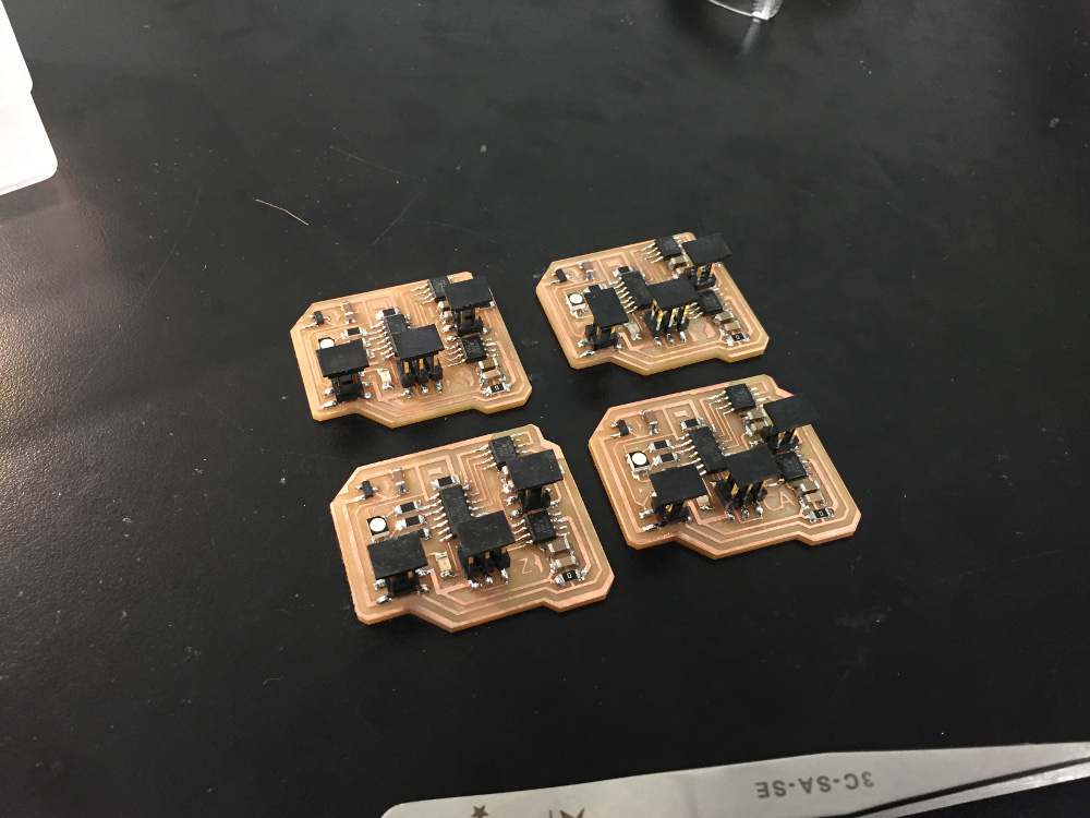
what I made: application for controlling stepper motor directly from the computer
Finding a way to connect to the stepper motor board
To keep things relevant to my final project, I decided to spend this week making sure I could send commands to a stepper motor directly from my computer. Ideally my final project would be a CNC mill, but the minimum product is a 3-axis moving device that would be able to take commands from the computer. I set out to determine how to best network my previous boards with minimal modification
Much of the difficulty here was finding out which pins on FTDI could be used to drive which pins on the 2x3 programming header. When I looked at it closely, I realized that the MISO and MOSI pins on the programmer weren't connected to anything else. As the "transmit" from the computer to the board is an input, I decided to use the MOSI pin which is connected to port PA6. It is listed as both the dedicated MOSI pin as well as PA6 for general interfacing purposes.
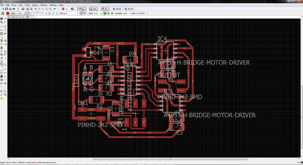
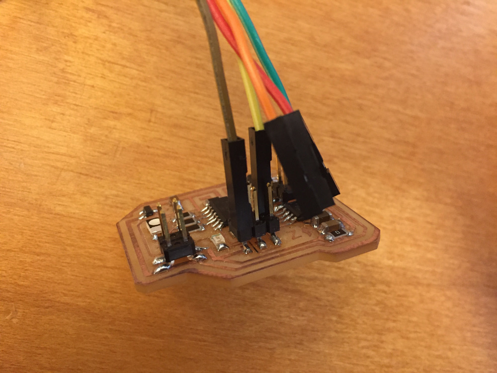
The schematic for the board I made is included above for reference. There are three pin-headers for each custom motor board; from left to right, they are a 2x2 12V power header, the 2x3 programming header, and the 2x2 stepper motor header. Since the power header and stepper motor header already have dedicated use, my only option was to leverage the 2x3 header for interface programming. I wanted to use FTDI communications but unfortunately did not have a dedicated 6x1 connector on the board. That's where I had to make a custom connector.
For serial one-way communications, the only FTDI pins I needed to have connected were GND and TX. Connecting 5V wasn't important in this case because each of my boards was powered by an external 12V supply regulated down to 5V.
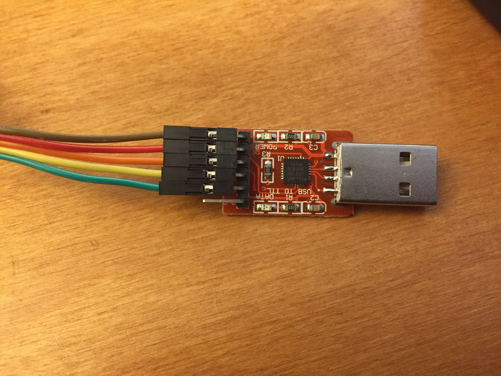
An aside here - the FTDI cable you see here is not a standard Digikey one - it is a much cheaper one I bought off Amazon at this link. I've found it to work just as well as the Digikey cable and, at only $3 total cost, it is much more cost efficient too.
Coolterm and sending data
From there, everything else was software. The FTDI cable established a connection with my Linux Virtual Machine and I decided to test sending characters to the boards using coolterm. Coolterm took some time to establish the connection with the board (had to make sure the baud rate on both the program and the terminal was set to 9600) but eventually I was successfully receiving characters and echo-ing them back from the board.
All it took then was to splice the TX/RX code for characters on the board with the stepper motor driver code so that whenever a "d" character was sent, the board would make a step in one direction and whenever a "a" character was sent, it would step in the other direction. I intend to use the WASD scheme ultimately for XY-planar control on the milling machine and maybe RF for up and down.
This week was definitely one of the shorter weeks I've had so far - I'll spend more time later on working on my final project.