Week 9: Input Devices
assignment: measure something: add a sensor to a microcontroller board that you have designed and read it
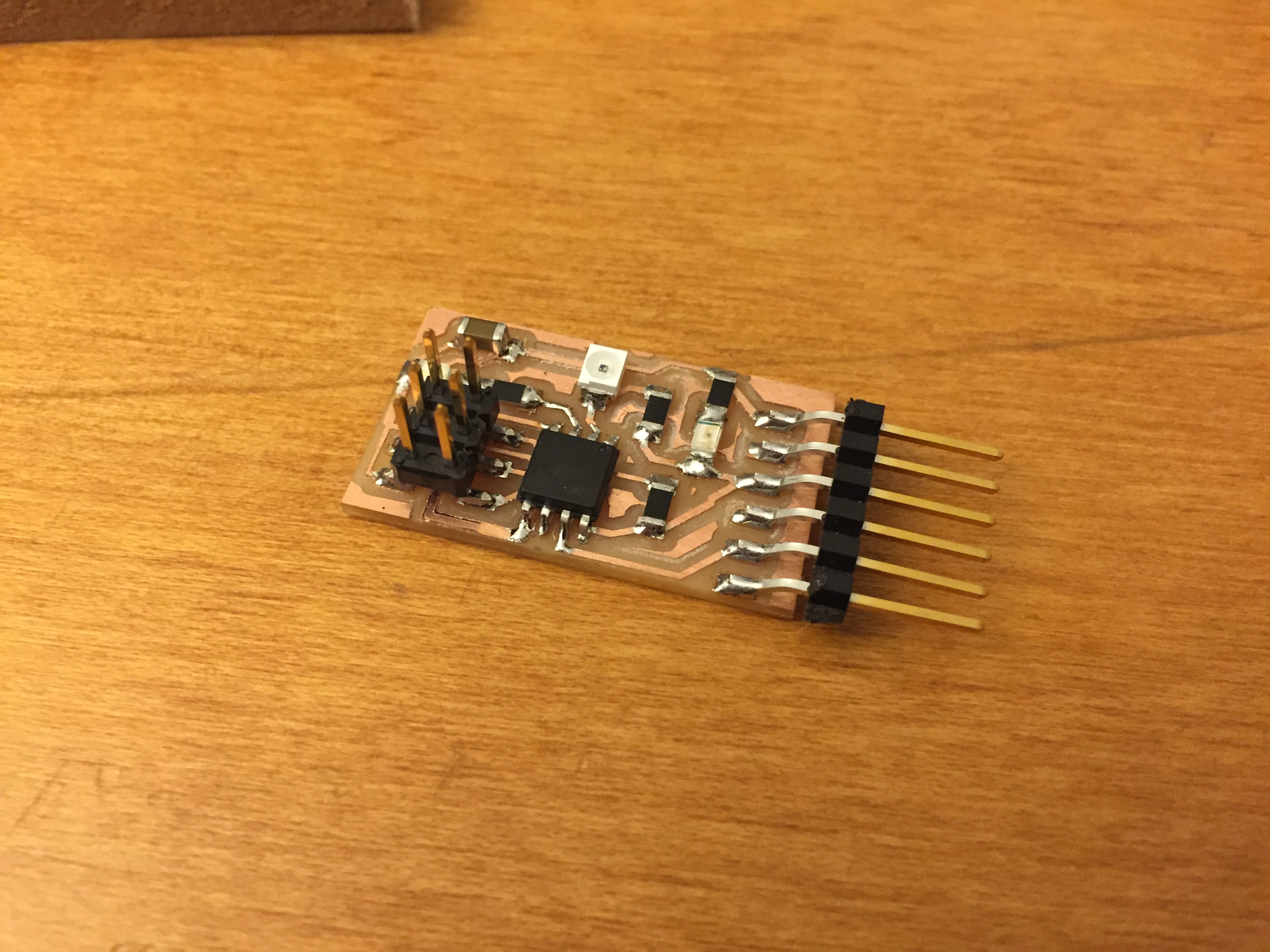
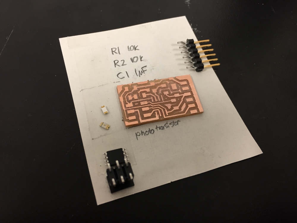
what I made: a board with a phototransistor to pick up IR light signals
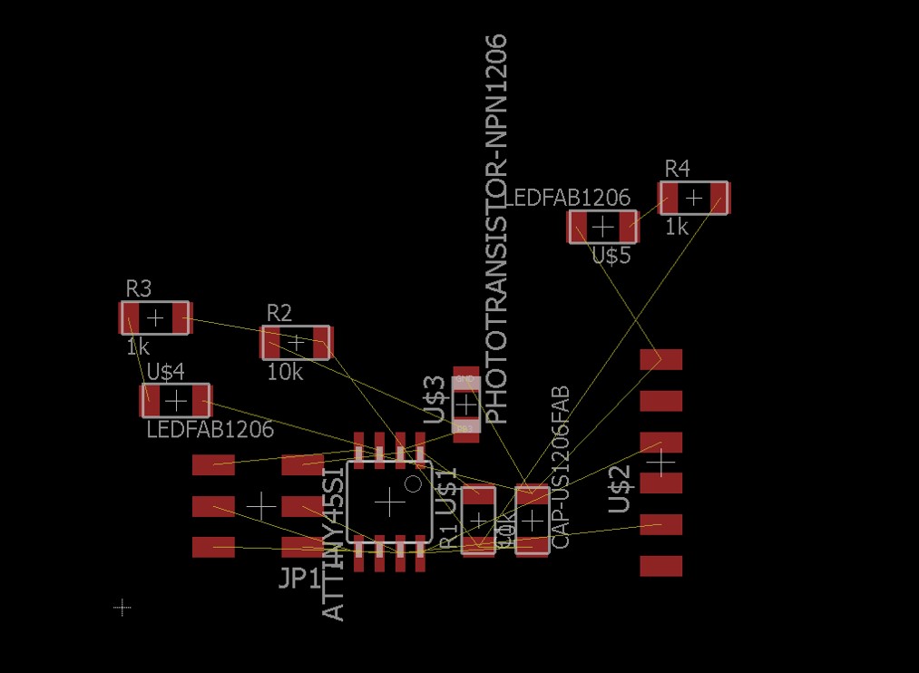
Designing the schematic and board
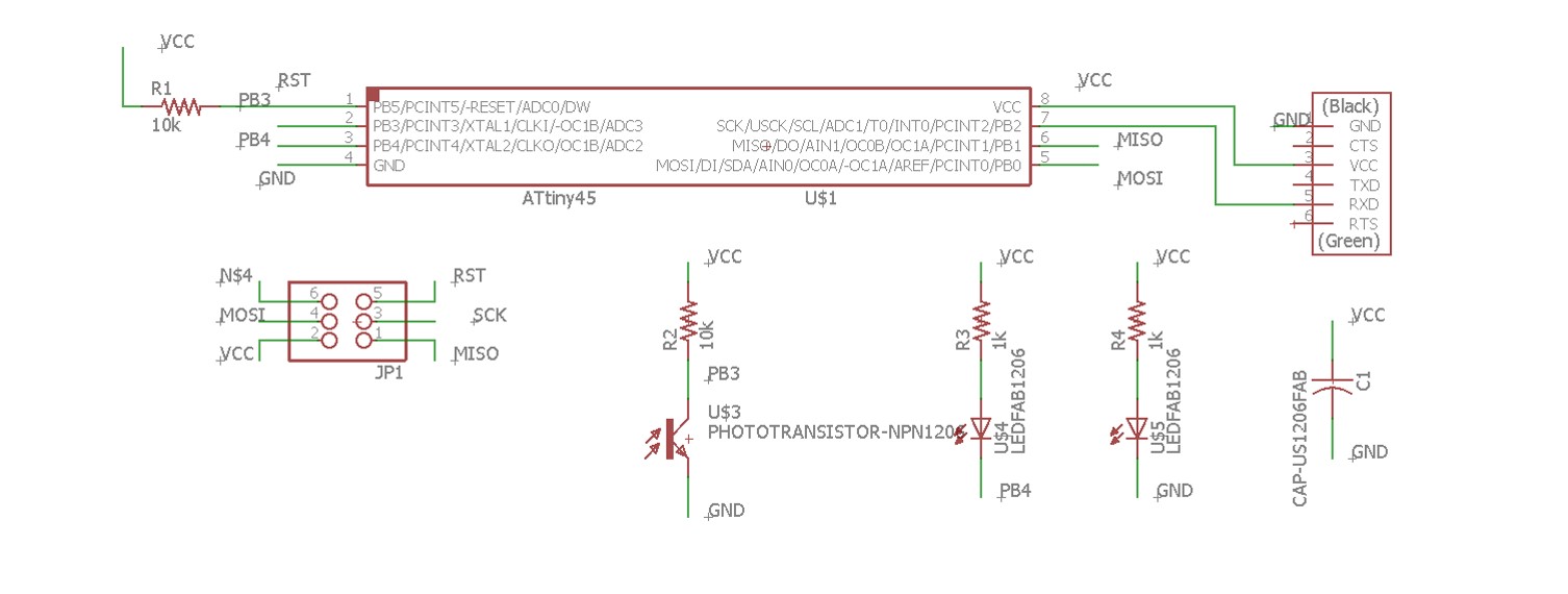
This week's project involved taking in an input from a sensor into the microcontroller. I decided to build a simple light sensor and detect the levels using a python program on the computer.
This is the first board I've made that uses the ATtiny 45 - I'm impressed by how small the processor is. It only has 5 I/O pins but can handle quite a bit of complexity even with just those 5 pins. I'll definitely keep in mind using the ATtiny45 for future projects that are IoT-type projects
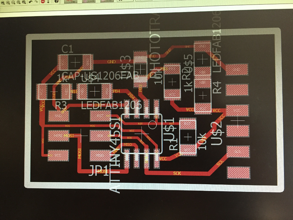
I laid out the board as compactly as possible - while many of my previous boards have taken an octagonal shape, this board came out noticeably rectangular. Fortunately, I did not have to use a single jumper resistor to make this board work.
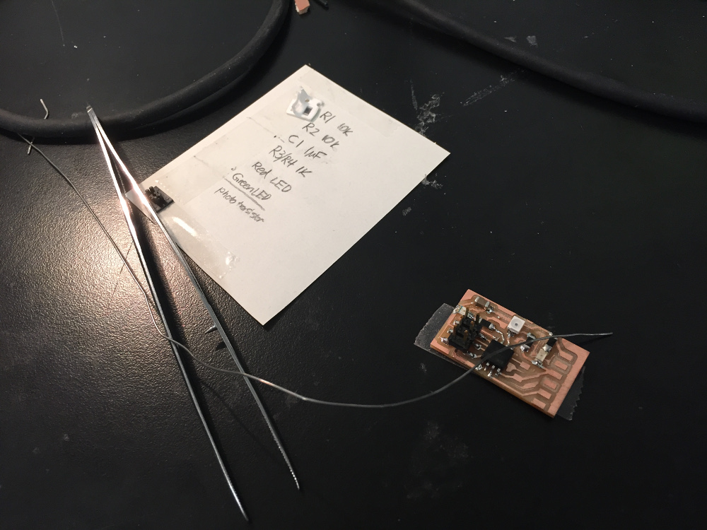
Soldering the board was very easy as well - The pins on the ATtiny45 were the most difficult part because of how small they were, but I've become experienced enough at soldering that it wasn't too much of a hassle. It took a couple tries to get the orientation of the LED figured out because datasheets for them are difficult to read and markings on the LEDs themselves are hard to interpret without a microscope sometimes.
Programming the board was extremely easy - I followed the same workflow as in my week 7 program upload documentation except instead with the proper code for the light sensor. The python program I used was the same as Neil's template program and I was able to initiate a connection via the FTDI cable. The code worked and the computer received the input from the light sensor!