Week 7: Embedded Programming
assignment: program your board to do something, with as many different programming languages and programming environments as possible
what I made: board where LED lights up when button is pressed
Fixing the board from week 5
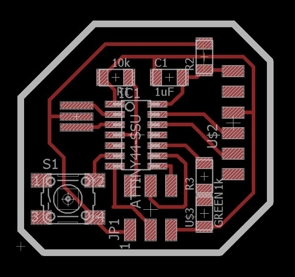
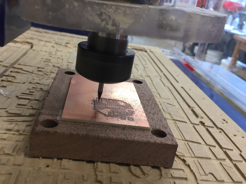
The board I had finished in week 5 did not inspire very much confidence as the traces I had chosen were 10 mil which was way too low. In order to avoid problems later on, I decided it would be best to remill the board using larger traces - 16 mil seemed like a more reasonable number. While I was at it, I changed up the geometry slightly and changed the outside cut to make the board a cooler shape.
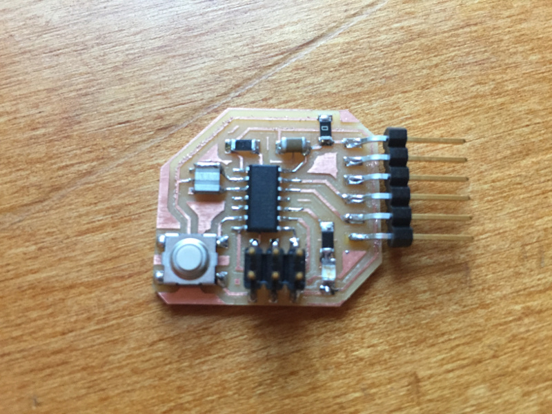
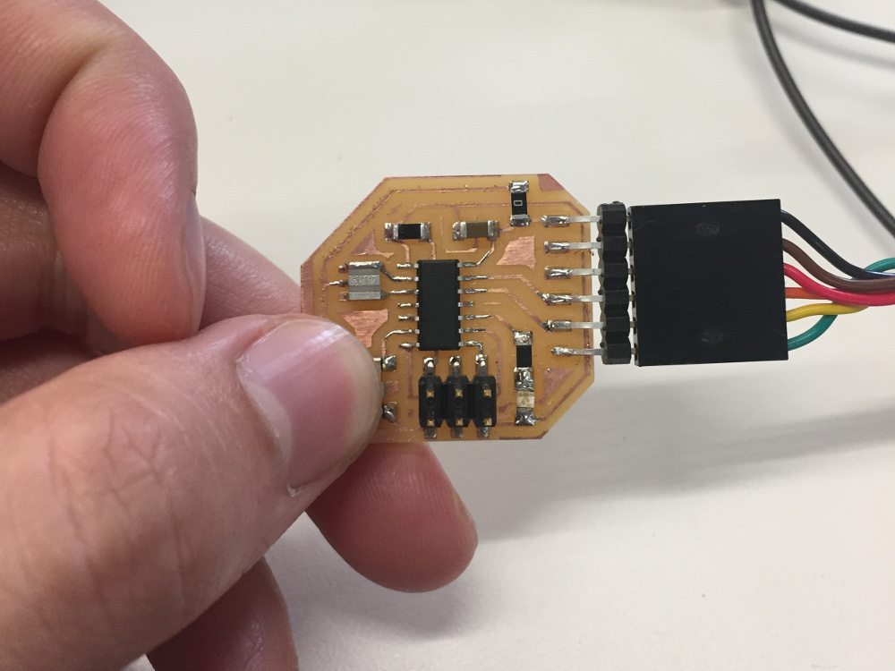
The resultant board is identical to the previous board except with much more generous trace width and a nicer soldering job.
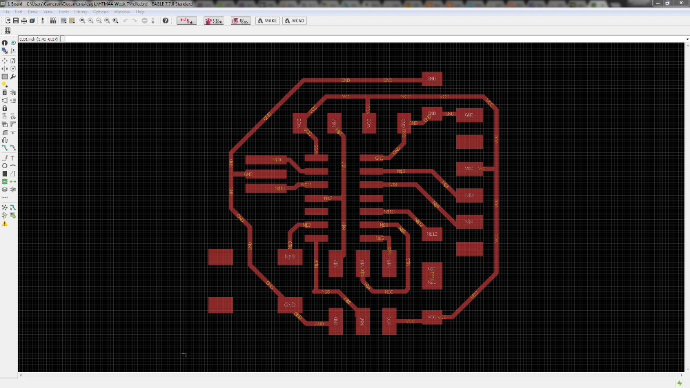
A quick aside - I've found the fastest way to export images from Eagle is via its built-in terminal. To prepare traces for export, run the following commands:
display none topThis causes the board to only display top layer traces. It removes all of the text and other garbage in the way.
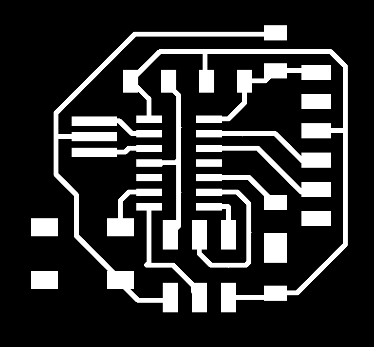
After this, run:
export image board_traces.png monochrome 600The traces on the screen is exported to a black and white 600dpi image in the same working directory as the board file. This file can then be inputted directly into fabmodules to calculate a cutting toolpath.
Now run:
display none dimensionAssuming you drew your traces in the "dimension" layer, this line clears everything but that dimension layer making it easier to export.
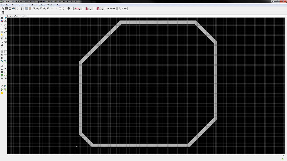
Finally, run:
export image board_outline.png monochrome 600Same line as above, except this time we're exporting the outline to a different file.

Using all of these export commands requires understanding the layers in Eagle and how they all work. It has a difficult learning curve because of all the abbreviations, but I found a very very very helpful Eagle layers explanation here that goes through what each of the layers means. The relevant ones that we will use to return the board to its "normal" view state are in the command below:
display none top dimension tPlace tDocu tOrigins tValues tNamesEach layer in Eagle has an associated number as well. The command can therefore be simplified to:
display none 1 20 21 23 25 27 51this can also be programmed into a hotkey for easy use.
Fabricating the PCB
Making a second board in Eagle allowed me to learn from many of the mistakes on my first board - regular traces on this board are now 16mil (0.016in) compared to 10mil (0.01in). The bit is a 1/64" (0.015625in) which meant the minimum distance between traces had to be at least that. To avoid any problems, I set the grid width to 16mil (0.016in) so I could always tell visually that were was at least 0.015625in clearance between any two traces on the board. I will continue to use this strategy in future boards to make sure I don't have any problems cutting around the traces.
Also, the board outline is cut out using a 1/32" bit (0.03125in) so it's important that my outer diameter is 31.25mil or larger. I usually create this layer using the dimension layer in Eagle. It is also important when exporting to make the outline image black so that fabmodules calculates a path that cuts within the line.
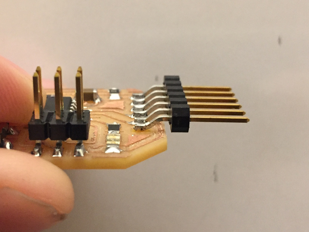
Another major thing I learned while making this board was the importance of leaving extra overhang to let the FTDI header rest on a solid part of the board. From the "most inside" part of the 6-pin header to the outside of the black part for the header, there is a distance of 0.3in. The plastic part of the six-pin header is about 0.1in wide, so this 0.3in tolerance allows some room if the soldering isn't done exactly on the pads. I will keep this in mind for future boards that use an FTDI cable.
Try #1: Programming with Windows
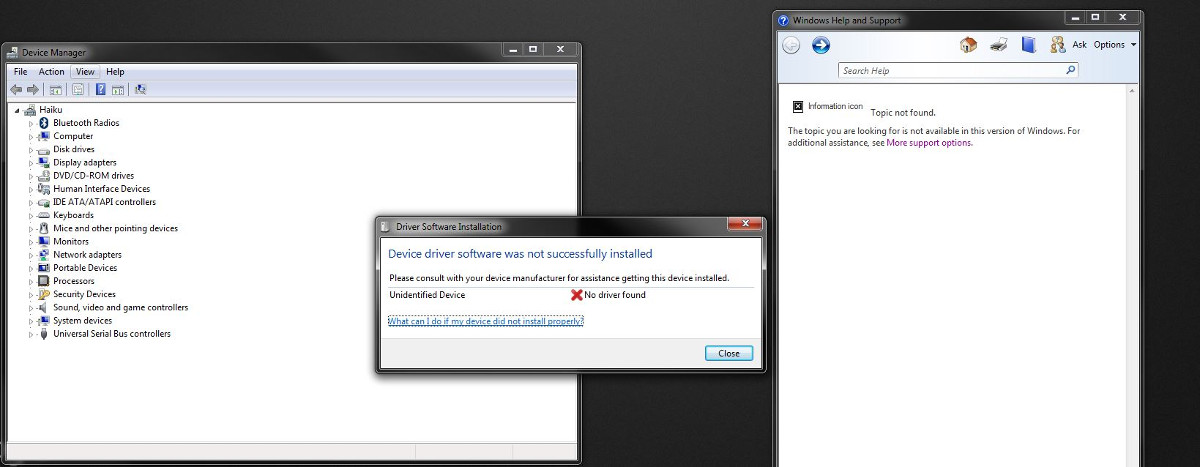
The hardest part of programming the board turned out to be establishing some sort of contact with the board through my Windows computer. Windows is a very difficult OS to work with sometimes because of the way it manages drivers as a part of device manager. I used this tutorial from Sparkfun on configuring the driver for Windows and got through the majority of the setup.
It turns out Windows didn't recognize the device at all and didn't even bother to pull it up on Device Mangler Manager. I cross-referenced another Windows tutorial found on High-Low Tech but it seems to make the same assumption that Windows will automatically recognize the device when attached. I tried restarting my computer but this did not affect Device Manager's ability to recognize the device.
To finish the project on time, I decided to put aside Windows for now. I figured this would be an issue to troubleshoot later and for the time being, I should use Linux which would provide a simpler environment for programming so I could instead focus on preparing the code in Arduino and getting the software side of things ready.
Switching over to a Linux VM
Fortunately, I have a Ubuntu Virtual Machine set up on both my laptop computer and my desktop computer precisely for situations like this in which Windows falls short. The process for installing avrdude on the Linux VM was very straightforward from the terminal and I followed the tutorial at this link. In short, I had to run the following lines
sudo apt-get install flex byacc bison gcc libusb-dev avrdude
sudo apt-get install gcc-avr
sudo apt-get install avr-libc
sudo apt-get install libc6-dev
This installed all the necessary packages to run avrdude / GCC on my Linux machine.
From there, I downloaded Neil's hello board code and modified the ports so that it would work with my board. The base code is exactly the same (the part used for turning on the LED) and the only changes I made were to match the ports to my board.
// button_44_b.c
// Adapted from How to Make (Almost) Anything 2016 Sample Code

  #include <avr/io.h>

  #define bit_get(p,m) ((p) & (m))
  #define bit_set(p,m) ((p) |= (m))
  #define bit_clear(p,m) ((p) &= ~(m))
  #define BIT(x) (0x01 << (x))

  // Button  PA7 (pin 6).
  // LED     PA3 (pin 10).

  int main() {
    bit_set(PORTA,BIT(7));  // Turn button pull up resistor on by setting PA7(input) high
    bit_set(DDRA,BIT(3));   // Enable pull-up resistor on the LED pin (PA3)

    while (1) {
      if(bit_get(PINA,BIT(7)))  // Button is up, turn off
        bit_set(PORTA,BIT(3));
      else                      // Button is down, turn on
        bit_clear(PORTA,BIT(3));
    }
  }
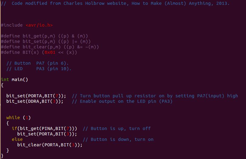
It is important here to make the distinction between ports and pins. Internally, the Attiny44 has predefined ports A and B which really just mean two sets of output pins. Each port has a pin 0, 1, 2, etc. These ports correspond to specific pins on the chip itself which are distinguished by counting counter-clockwise starting in the upper left. As a result, port A7 has the button input and it is physical pin 6 while port A3 has the LED output and it is physical pin 10. Below is a picture of the code as viewed in the VIM code editor in my Linux terminal.
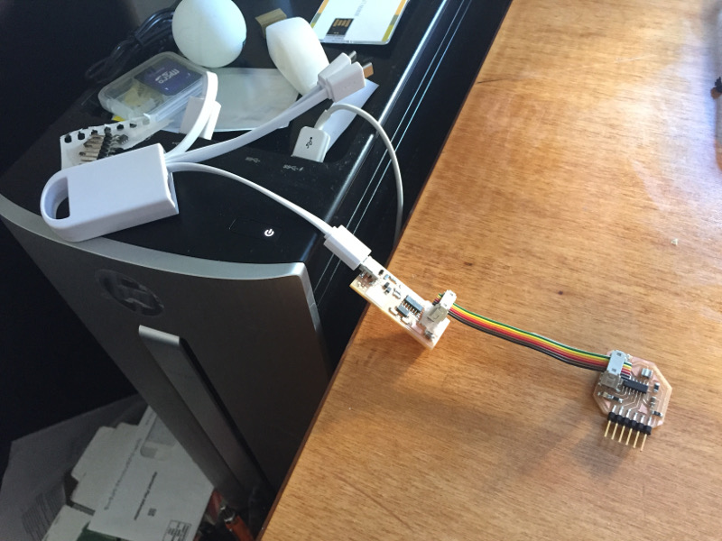
Putting the code onto the Attiny44 is a three-part process - the first part involves establishing contact with the Attiny44 via a programmer. I used the FabISP that I made in week 3 as my programmer for this project. I used a USB to USBmini cable to connect my computer to the FabISP, then a 2x3 header cable to connect from the FabISP to my custom board. To check if the orientation of the cable is correct, I typed the following command into the terminal.
avrdude -c usbtiny -p attiny45This pings the programmer and attiny44 to see if they are recognizing the computer's communications. Once avrdude returns that a successful connection has been made and the attiny44 is ready for programming, I cd over to the directory that contains the c code and makefile. I use the makefile to compile the c file into hex by running the command:
make -f button_44_b.makeA quick ls will reveal that button_44_b.hex has now been created in the directory and that file contains the hex code for upload onto the microprocessor. To upload the code using avrdude, we run the command:
make -f button_44_b.make program-usbtinyThis is the same as the last line except with "program-usbtiny" at the end. This runs a specific line in the makefile that allows us to upload the code onto the microprocessor. With that, the attiny44 is fully programmed!
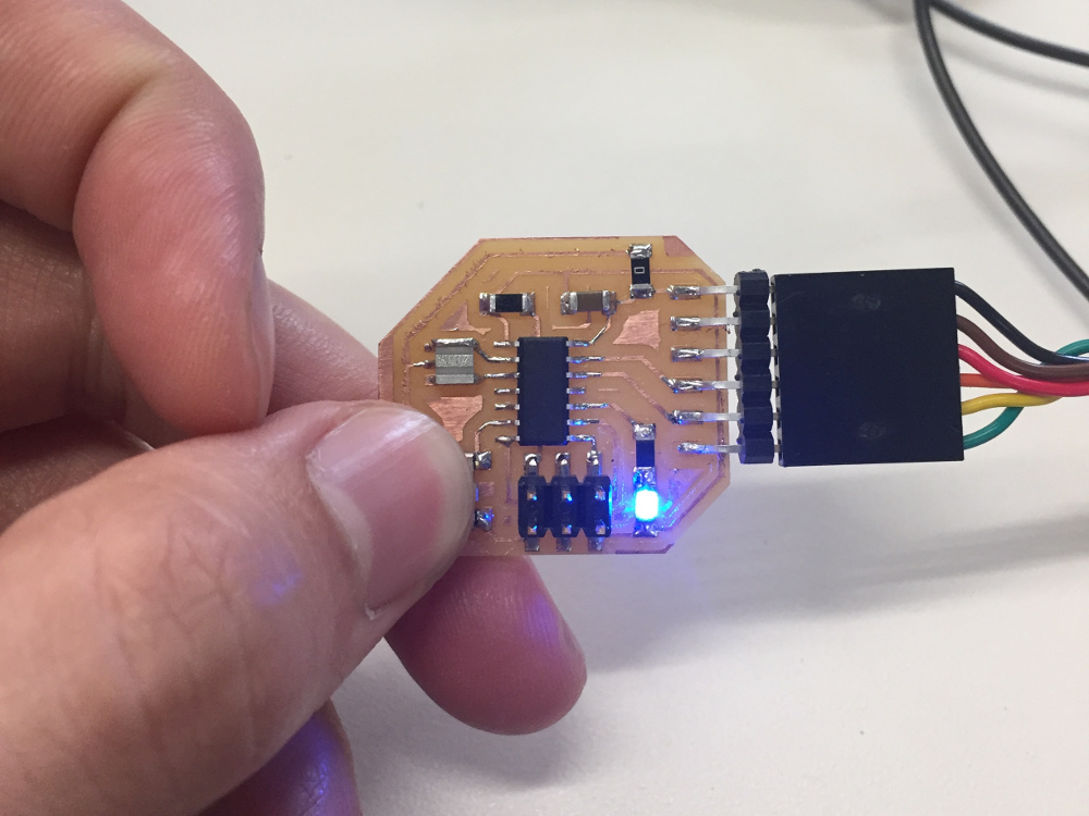
The LED turns on when the button is pressed - the programming was successful!