| Back to Index |
I'm a student in the Harvard Grad School of Ed's Technology, Innovation, and Education program, and have always loved making things with my hands. So when the opportunity came up to take a course at MIT called How to Make (Almost) Anything, I knew I had a fun challenge ahead of me.
I have a background as a professional actor and writer, and I'm interested in creating science education content that's emotionally and experientially engaging. I especially love astronomy and cosmology. Since space is so big and physically inaccessible, we're limited to learning about it through visuals and verbal explanations. With this in mind, I've been thinking about how to teach astronomy in a more experiential way. The final project for this course presented the perfect opportunity to do so. (If you're curious, click here to check out some of the other ideas I batted around, ranging from a pyro-organ to a model airplane, plus some other astronomy stuff.)
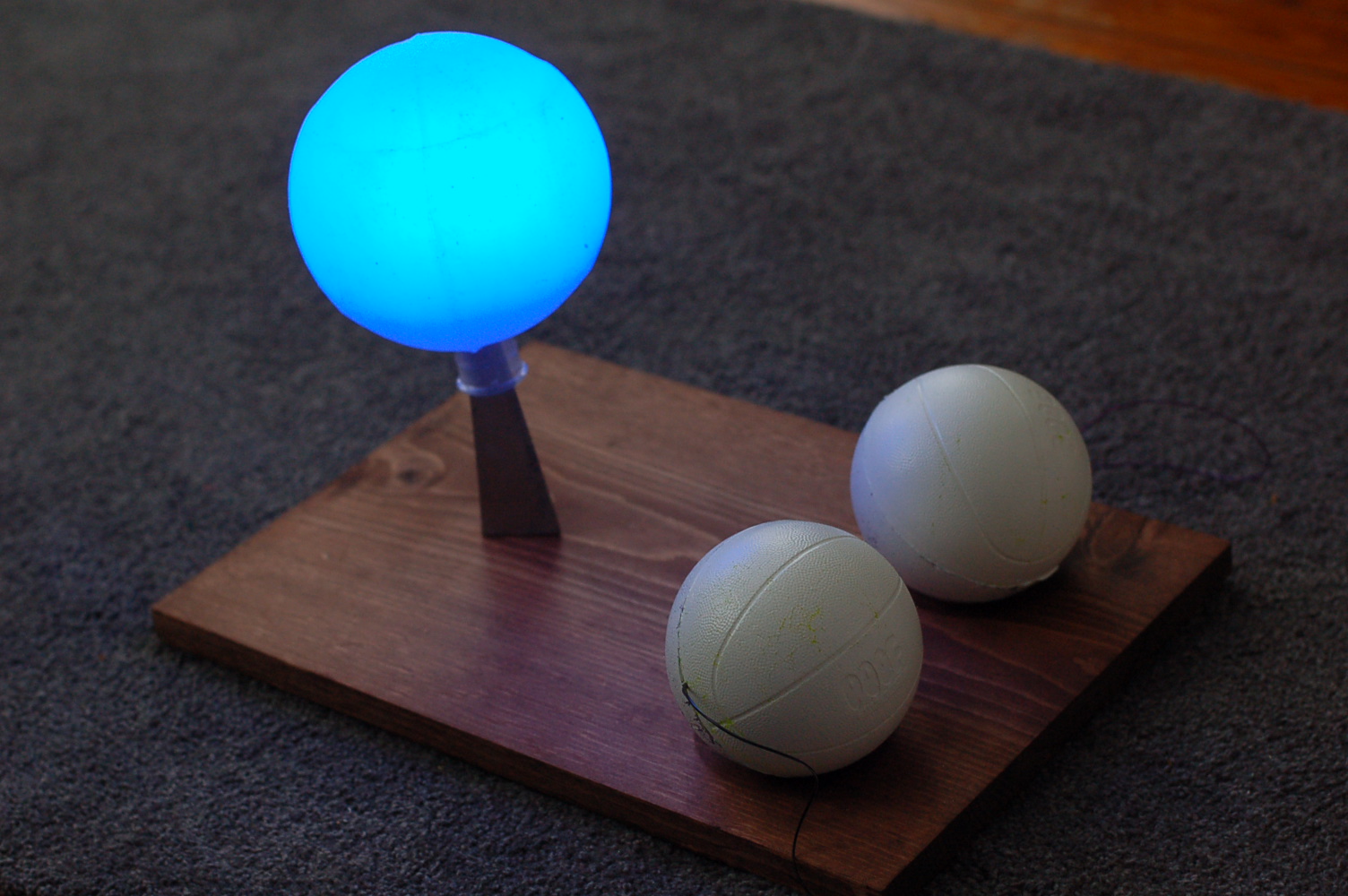
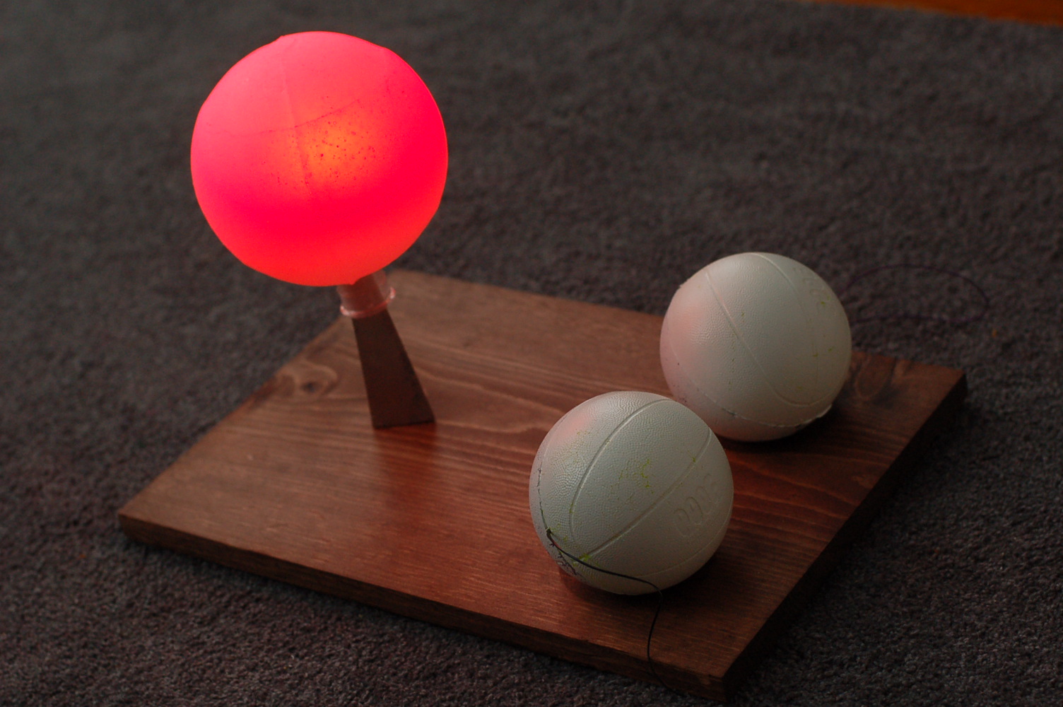
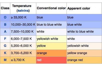
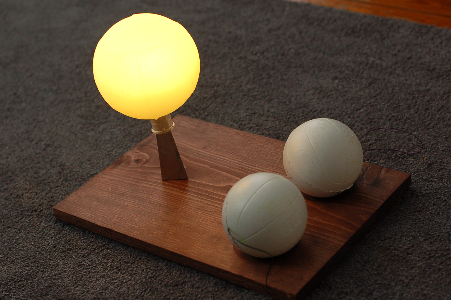
Stars in the night sky burn at different colors.
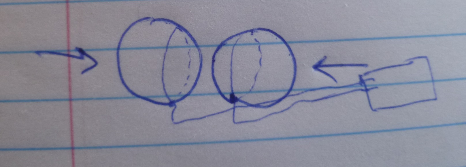
There is a relationship between the color / temperature at which a star burns, and the amount of pressure fusing atoms together in the star's core. My project puts these atoms in your hands, allowing the user to physically experience this relationship. The harder you mash the two white "atoms" together, the hotter (read: bluer) the "star" glows!
During Inputs Week, Neil described how it's possible to place a squishy material between two electrodes, and using step-response, effectively create a type of force-sensor. I realized I could place the two electrodes inside some squishy "atoms", and using the step-response values, control the color and brightness of an RGB LED inside a translucent "star". (I've looked, and I don't think anyone has made something like this before. Though I wouldn't be surprised if they had.)
This was a good challenge for my making abilities and interests. I love the physical challenge of making something: how to identify and navigate the various constraints, and how to make it as cleanly and aesthetically pleasing as possible. Coding, on the other hand, is a foreign language that I only began to understand in this class. As such, the coding for this project, while non-trivial, was far simpler than some of the coding being done in other class projects. I just had to translate some step-response data to control some LEDs. I mostly got there, as you'll see. I was happy to devote more energy to the physical presentation of the thing.
My project involved basic functionality and simple shapes. How hard could it be to make?
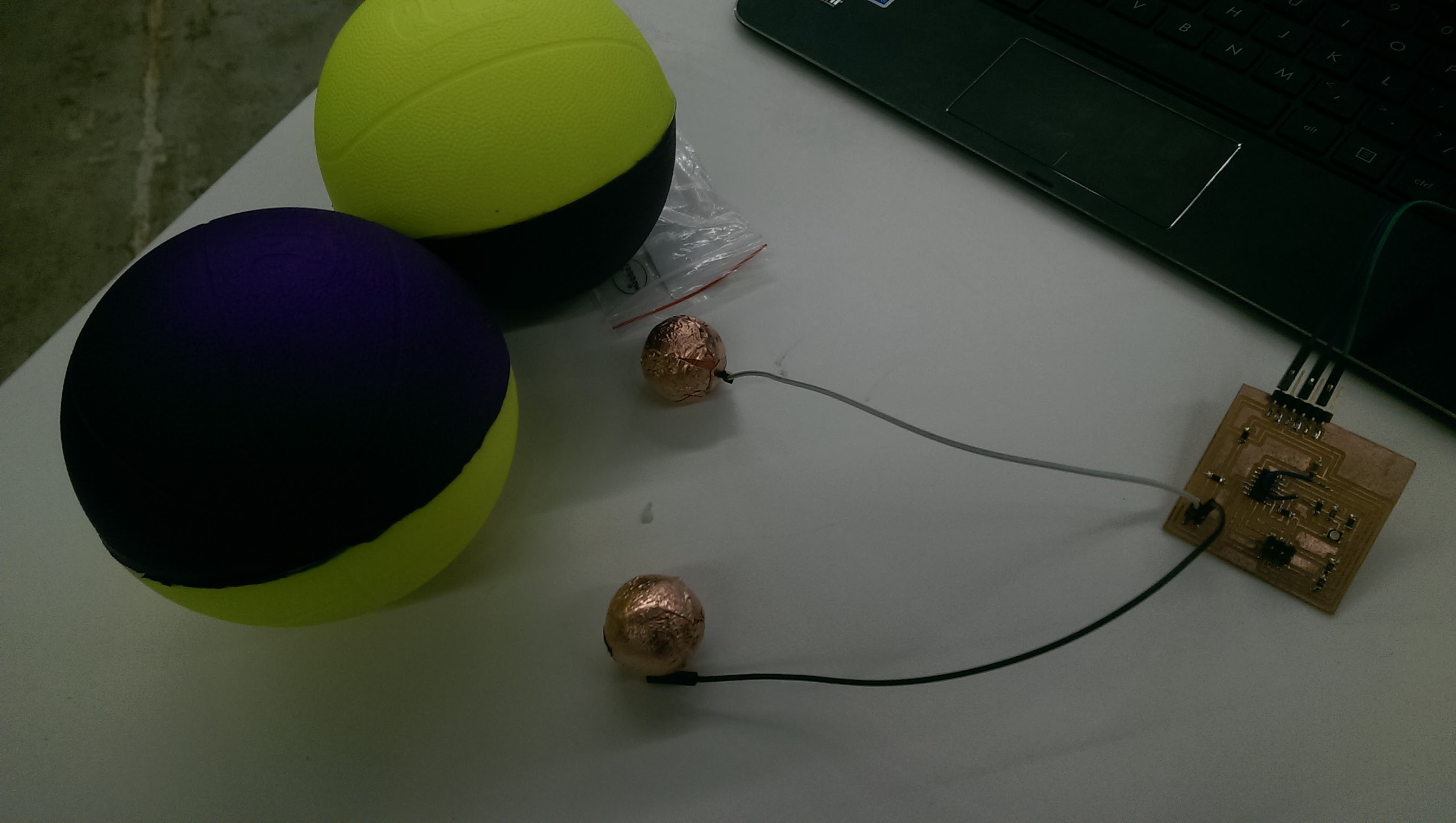
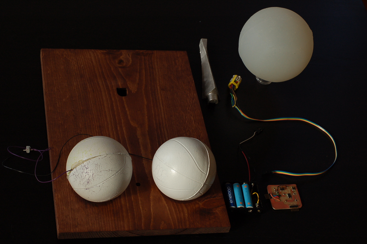
4" Squishy foam balls with a copper-coated, 3-D printed core. Spray-pained with Krylon ColorMaster
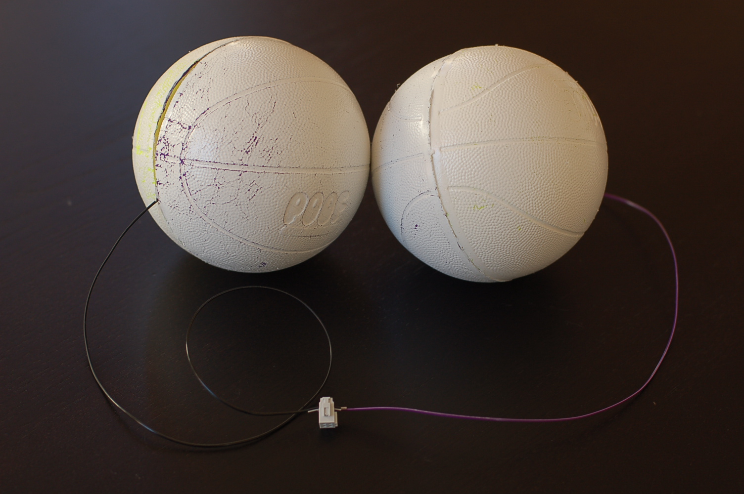
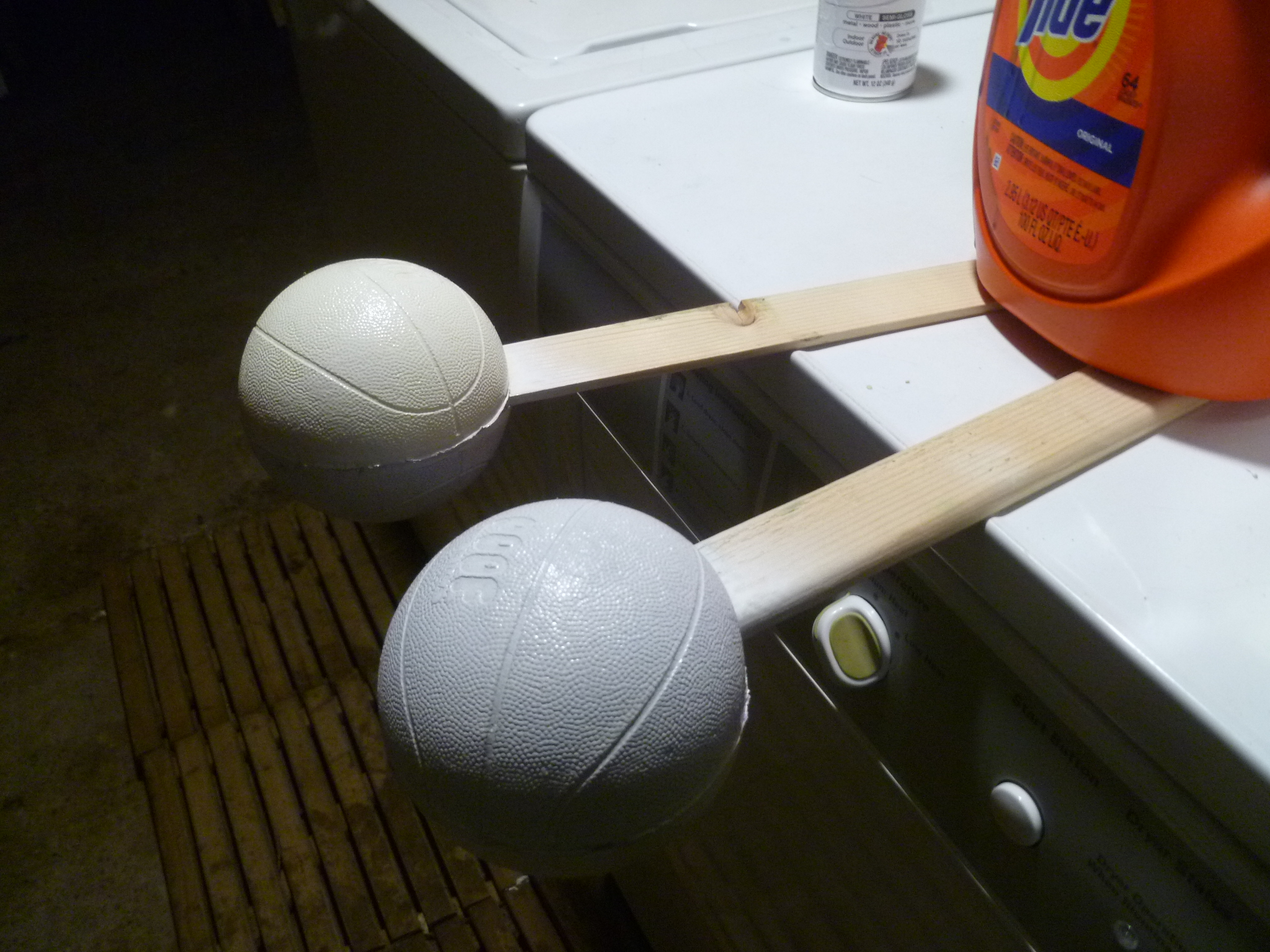
Admittedly, I didn't make the atoms, I bought them. I wanted a material that was squishy but firm, such that you'd have to exert a non-trivial amount of force to squish them as closely together as possible. I wasn't sure what material to use, whether we'd have access to it, whether I could mold with it or would need to carve it out (like from a block of memory foam?), etc. I wanted the spheres to be perfectly round, I didn't want them to look hand-made (i.e. imperfect). I remembered an old Nerf football I had that was exactly the right amount of squishy. I ordered a few sizes of a few squishy balls I found on Amazon, and the 4" POOF balls were the winner.
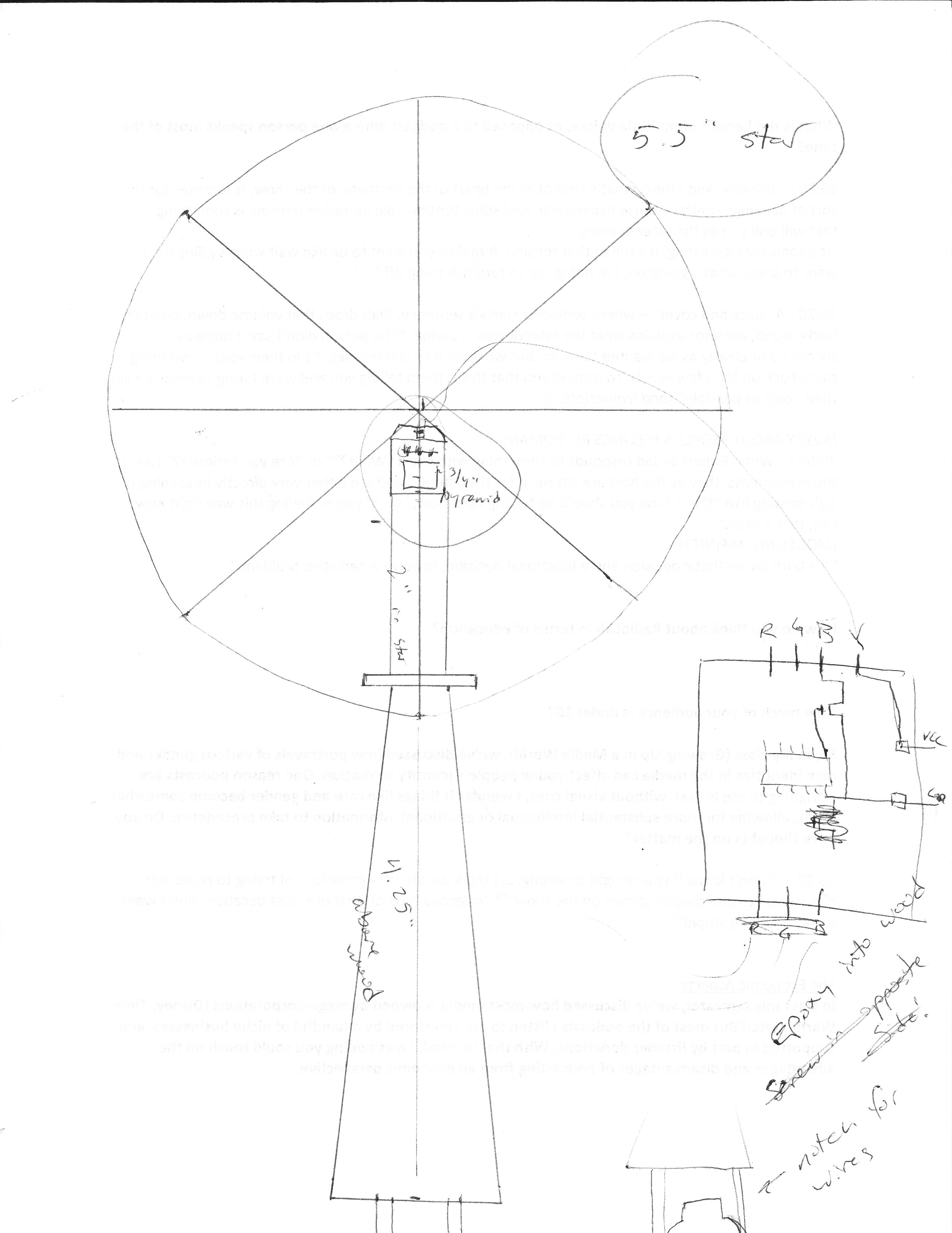
This 4" measurement determined the scale of the rest of the project. The Star had to be bigger than the Atoms, and the pedestal the star would sit on would be best if it could be milled out of one piece of 1.5" x 3" x 7" machineable wax. A 5.5" star felt like the right size, but proved to be a challenge to make. (More on that later.)
I 3-D printed a couple spheres, sliced deep into my foam balls, and found the 1" printed core to be the right fit. I hand-wrapped it in copper sheeting, soldered some wires on, and called them Atoms during Week 12. They then got spray-painted white, the traditional model color for hydrogen. The paint will crack, and they're still clearly textured to look like toy basketballs, but I'm okay with that at the moment.
The step-response works by measuring the capacitance between two electrodes (the copper-plated atomic cores). PROBLEM: When it came time to program everything, I discovered the capacitance between the wires themselves was being measured, rather than that between the copper cores. I needed to somehow sheild the wires from interference. Wrapping the wires in tinfoil and electrical tape did nothing. I tried running a ground cable up to each electrode, but that didn't seem to help, either. I ended up running the wires in opposite directions and out from under the board, to keep them as far apart as possible. While this meant I now had a hole milled in the middle of my board for no good reason, it at least works somewhat better now. (Tinkering with code also helped, see below.)
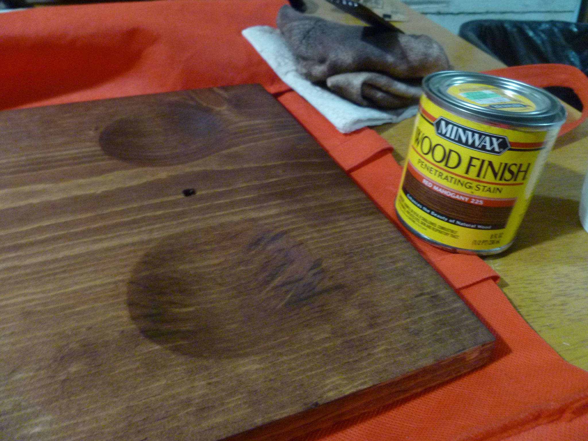
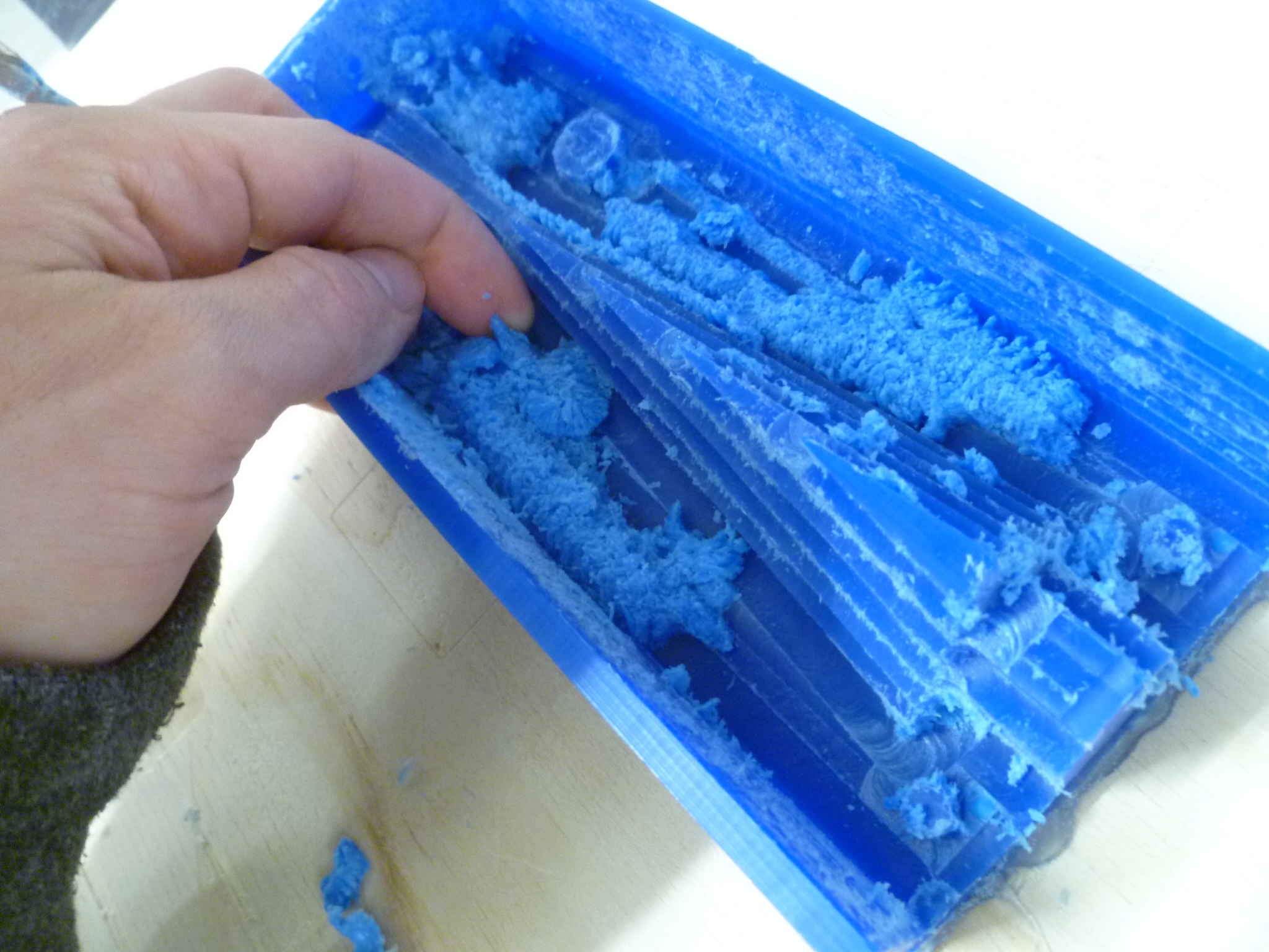
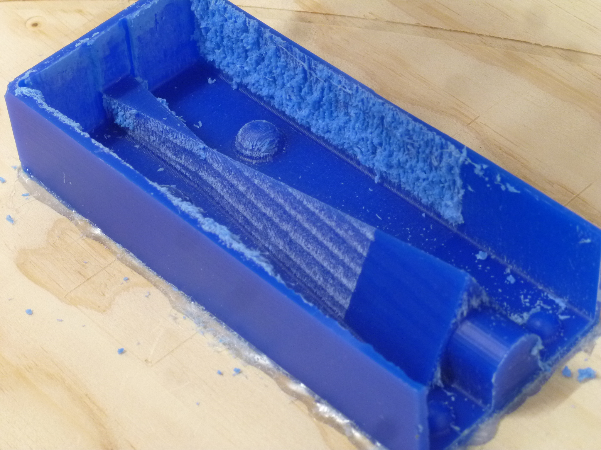
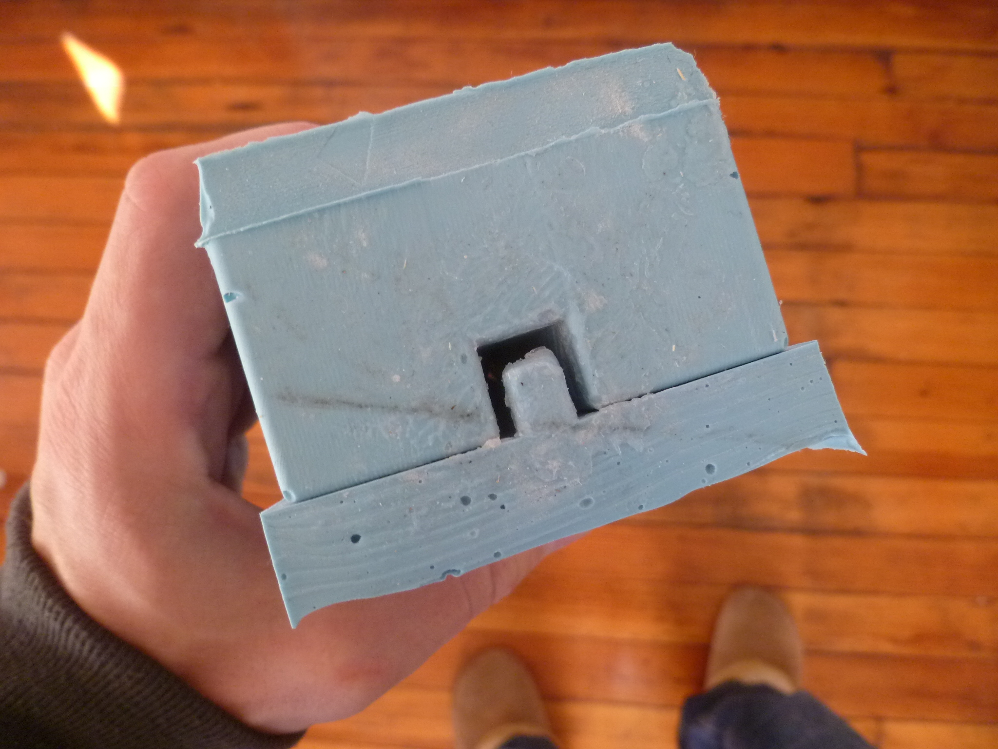
Milled pine, stained with Minwax Red Mahogany, sealed with polyurethane
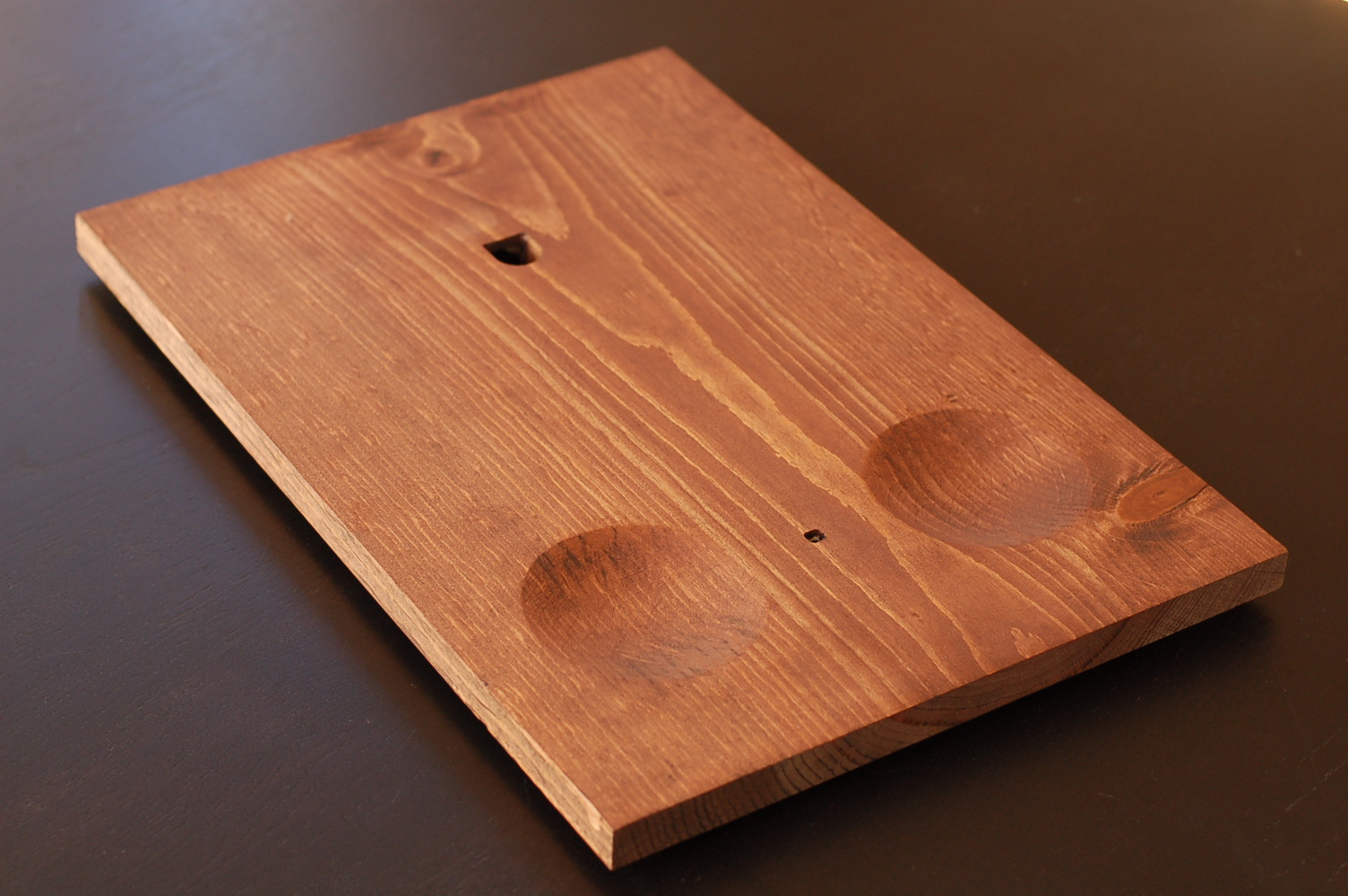
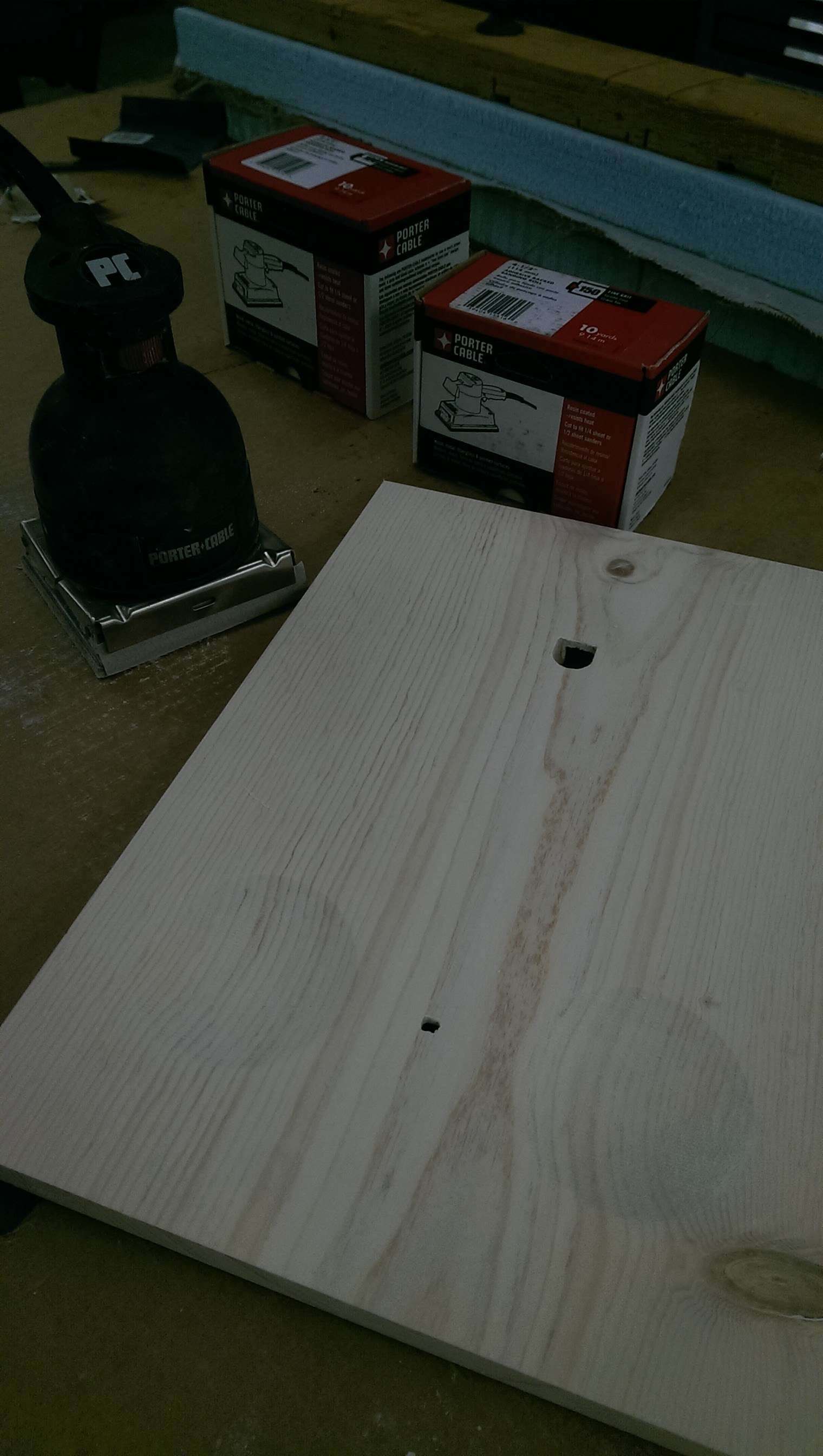
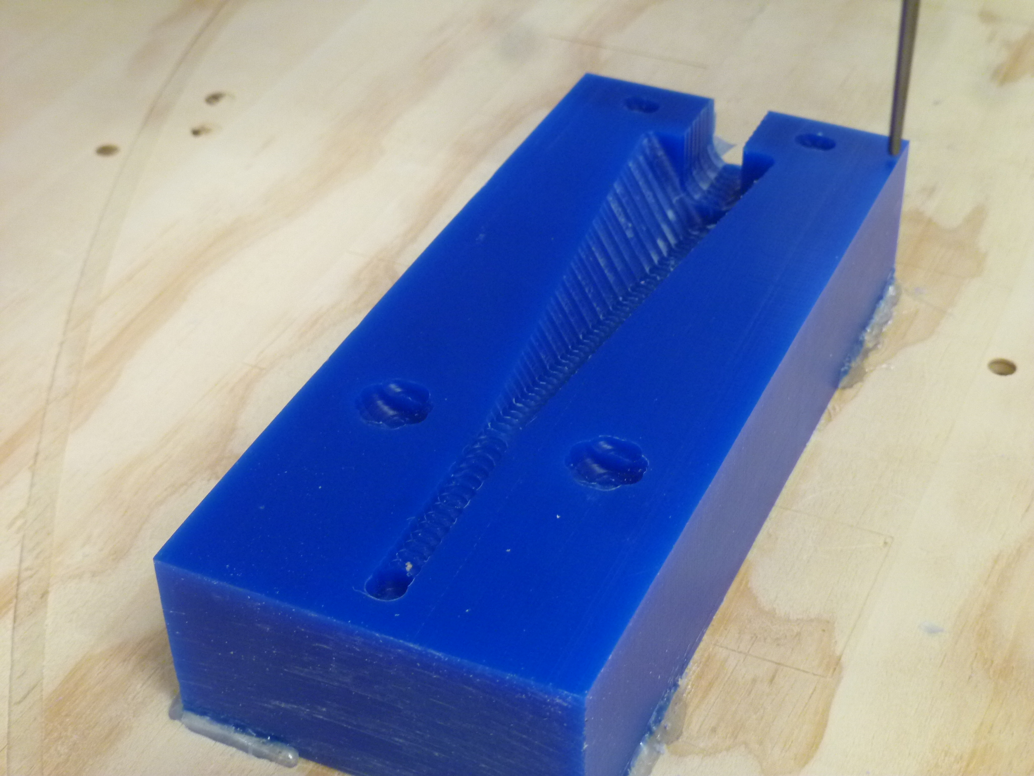
The base board was the second physical thing I acquired. I got it for about $5 at the local hardware store. They didn't sell by the foot, only in longer planks, but offered to sell (and cut to length) a piece of remainder .75" x 11" stock. This width worked perfectly with my 4" atoms. #meanttobe
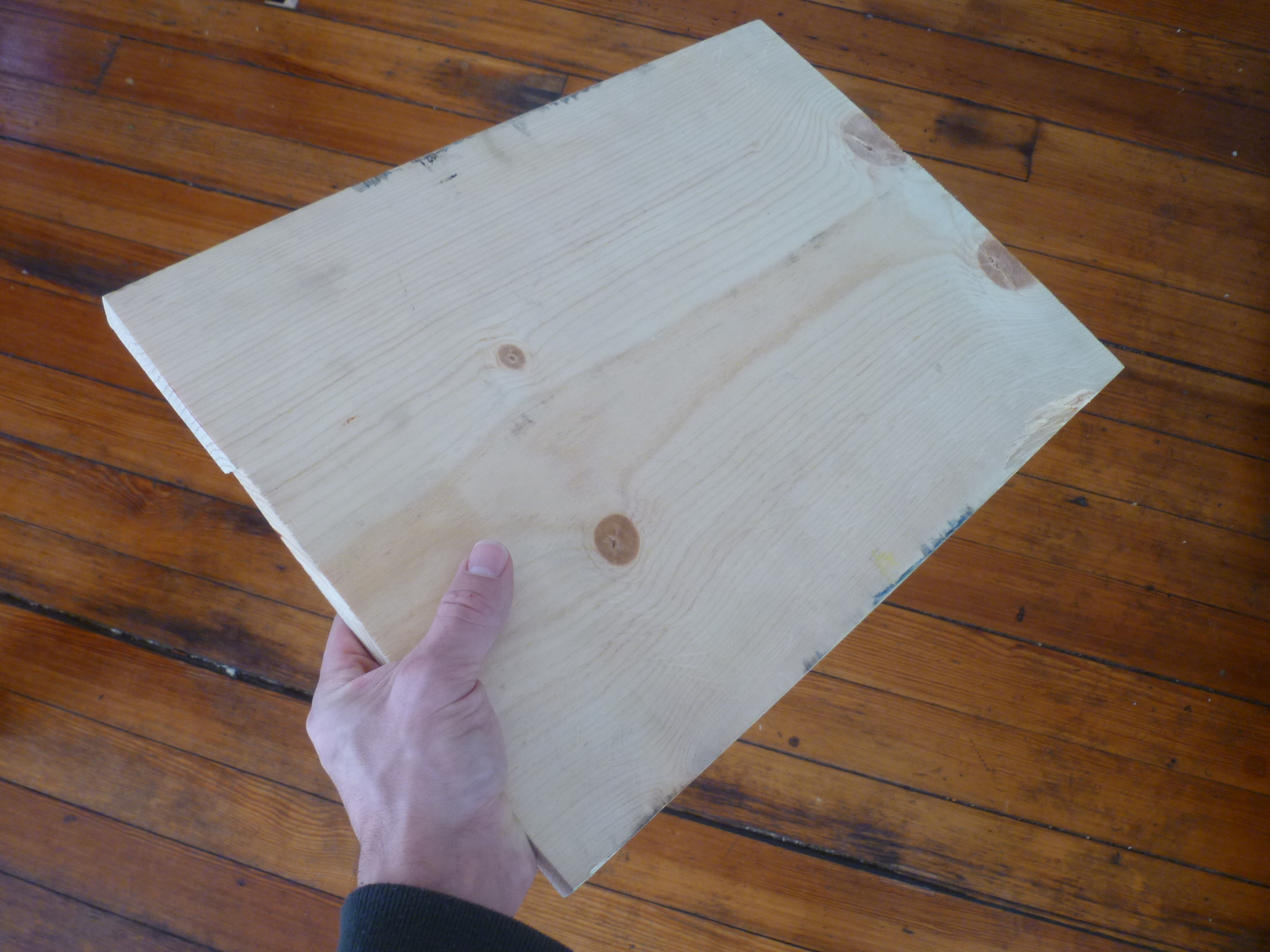
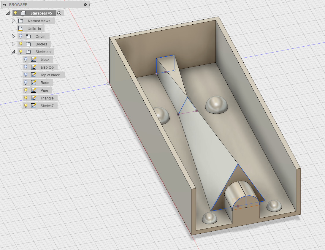
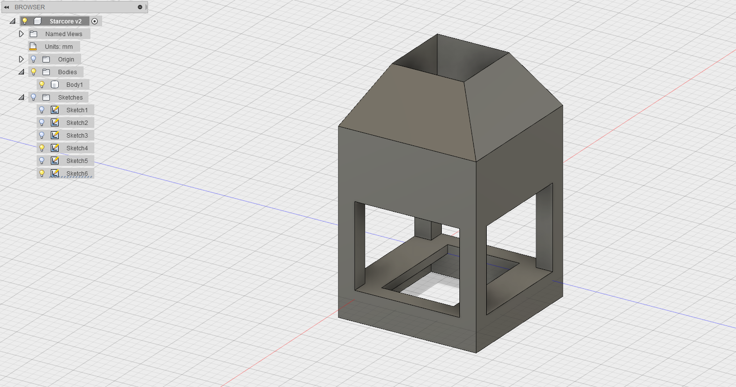
I designed the top and bottom in Fusion 360, ensuring that the divots milled out of the top didn't interfere at all with the room for the circuitry milled out of the bottom. It was pretty close at points, and I had to finagle the design accordingly. I exported the board as an STLs, and generated the tool path for our desktop ShopBot using PartWorks 3-D. The top's rough cut was done with a .25" downcut endmill, the finishing pass a .125" tapered ballnose, both at a feed rate of about 2" / sec, a plunge rate of 1" / sec, and a spindle speed of 12k RPM. I don't know if those were the right figures, but they did the job.
(seen here with Pedestal, which was made before the board was designed.)
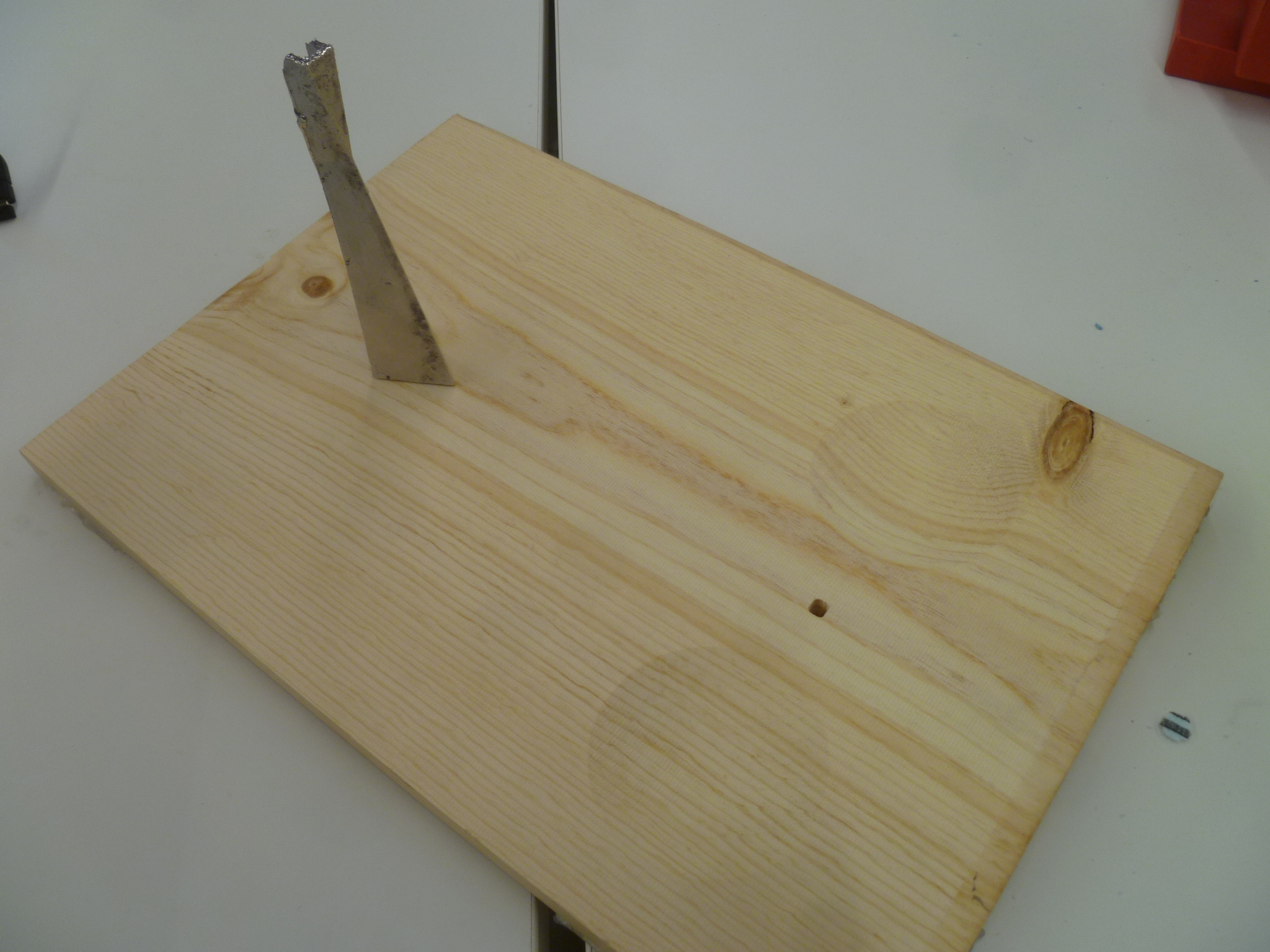
I was about to mill out the bottom (after the D-shaped hole for the pedestal had already been milled out from the top) when I caught a potential issue. I had to remove and flip my board over to mill the bottom, and in doing so, I had to reset where the XYZ zero was set for the ShopBot. If I calibrated the XYZ zero incorrectly the second time, or if the pedestal hole was off-center (in my design (it wasn't) or in reality (it was – I told the ShopBot my piece was 11" wide, when in reality it was 11.125" or so), the hole would be milled out twice in slightly different locations, resulting in a giant hole where I needed a snug fit for the pedestal. I went back into Fusion, plugged the hole on the bottom, and recreated the tool path. It's a good thing I did, because lo and behold, it would have been about 1/8" off in both the X and Y directions.
I knocked out the little piece between the wire trough and the pedestal hole with a hammer and chisel. I had used a 1/8" tapered ballnose as my finishing endmill, which left a regular series of ripples on the top surface, distracting from the lovely wood grain. I sanded it down with a power-sander, getting into the divots by hand.
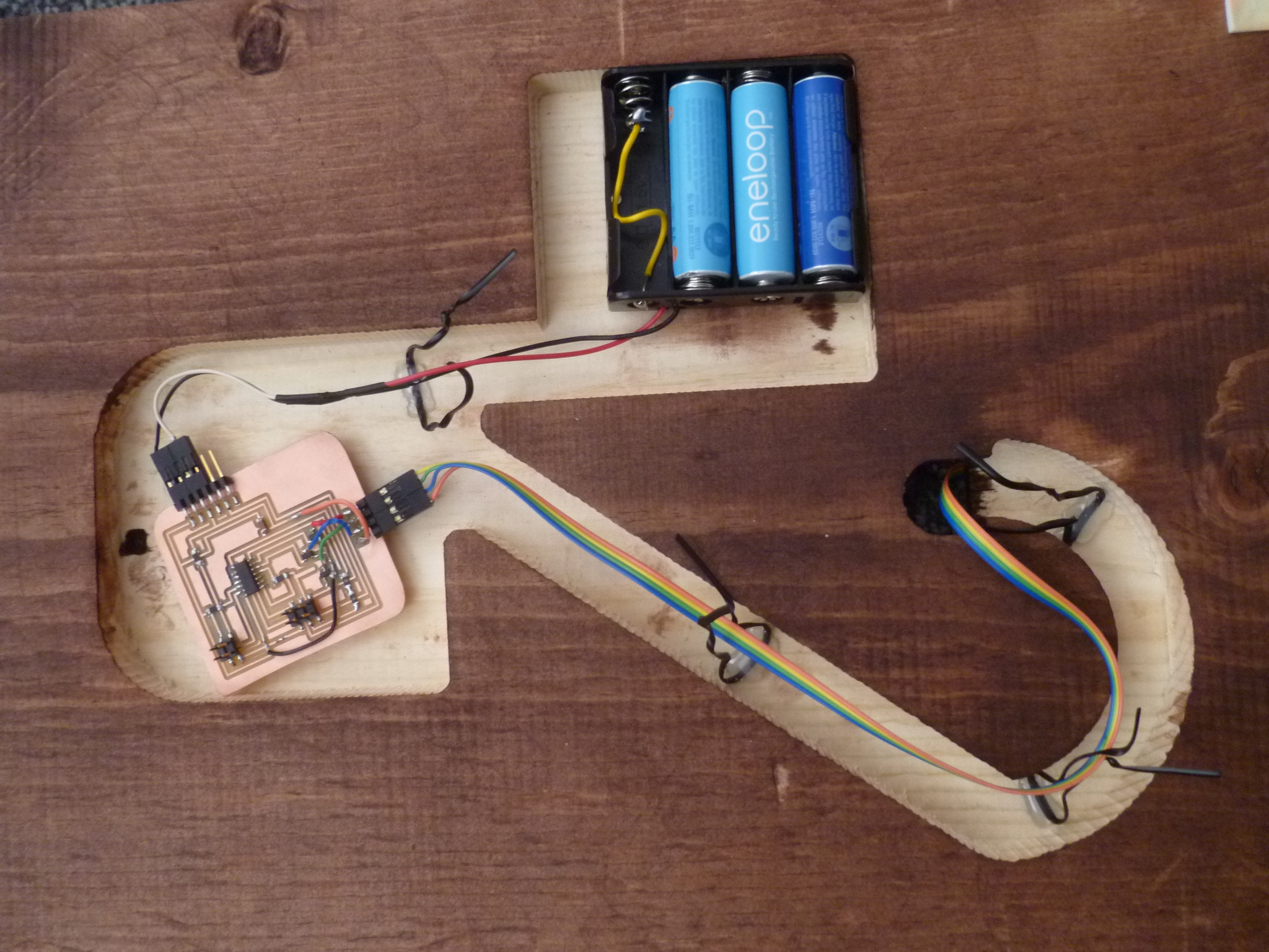
I wanted everything to disassemble for easy transport, so the battery case and AVR board are held in with velcro. Some rubber footpads, thickened with foam tape to give components enough room underneath, finish off the base board.

A 4-AA battery holder modified for 3 AAs, found in Harvard shop
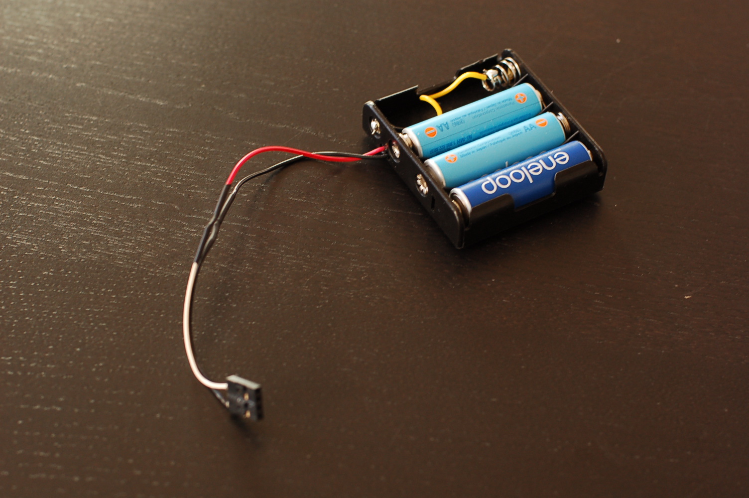
Rob Hart in the Harvard shop helped me talk through my power needs and solve them. I wanted a clean look, which meant no power cables snaking out from under the board. I wanted onboard power. I also wanted enough to power 4 RGB LEDs to shine through an as-of-yet undetermined thickness of MoldStar 20T, my translucent silicone of choice for the 5.5" star. Long story short, after consulting some datasheets over some concern about cooking the ATTiny44 controlling the whole thing, we determined that 4.5 volts coming from 3 AA batteries would work. By included some transistors on my board, to handle sending power to the LEDs, I could bypass concerns of cooking the ATTiny44 entirely, because that power wouldn't be going through it. Or something to that effect. But Rob seemed confident.
I wanted to use the Voltage (VCC) and Ground (GND) pins on my AVR board for both power and the option of FTDI serial communication, so I could tell whether my step-response was working or not. (I got that working during Week 12. So rather than soldering the battery wires to the AVR board directly, I put them in crimp harnesses. This way, I could also turn it on and off by plugging or unplugging power, rather than by uninstalling batteries.
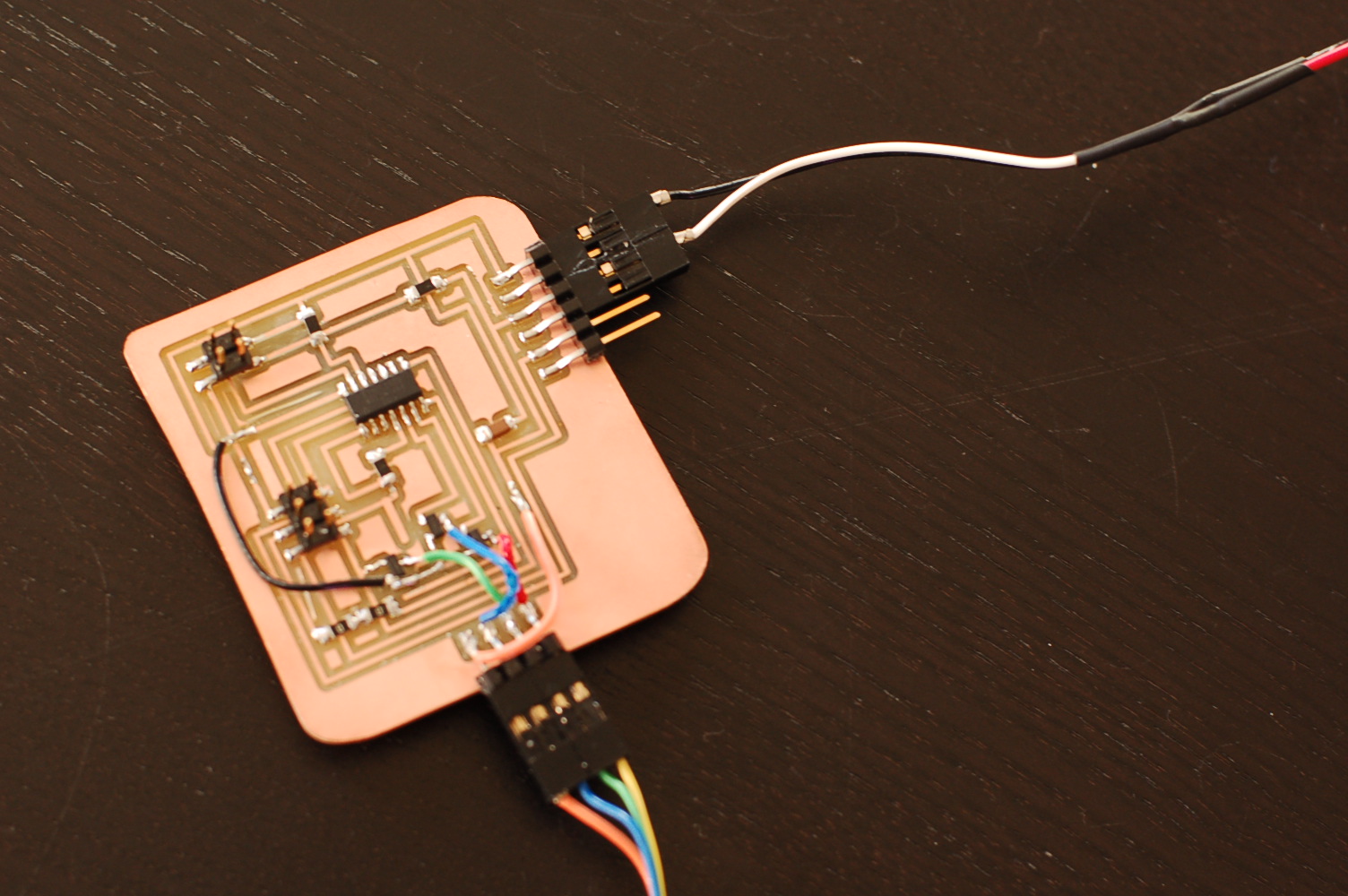
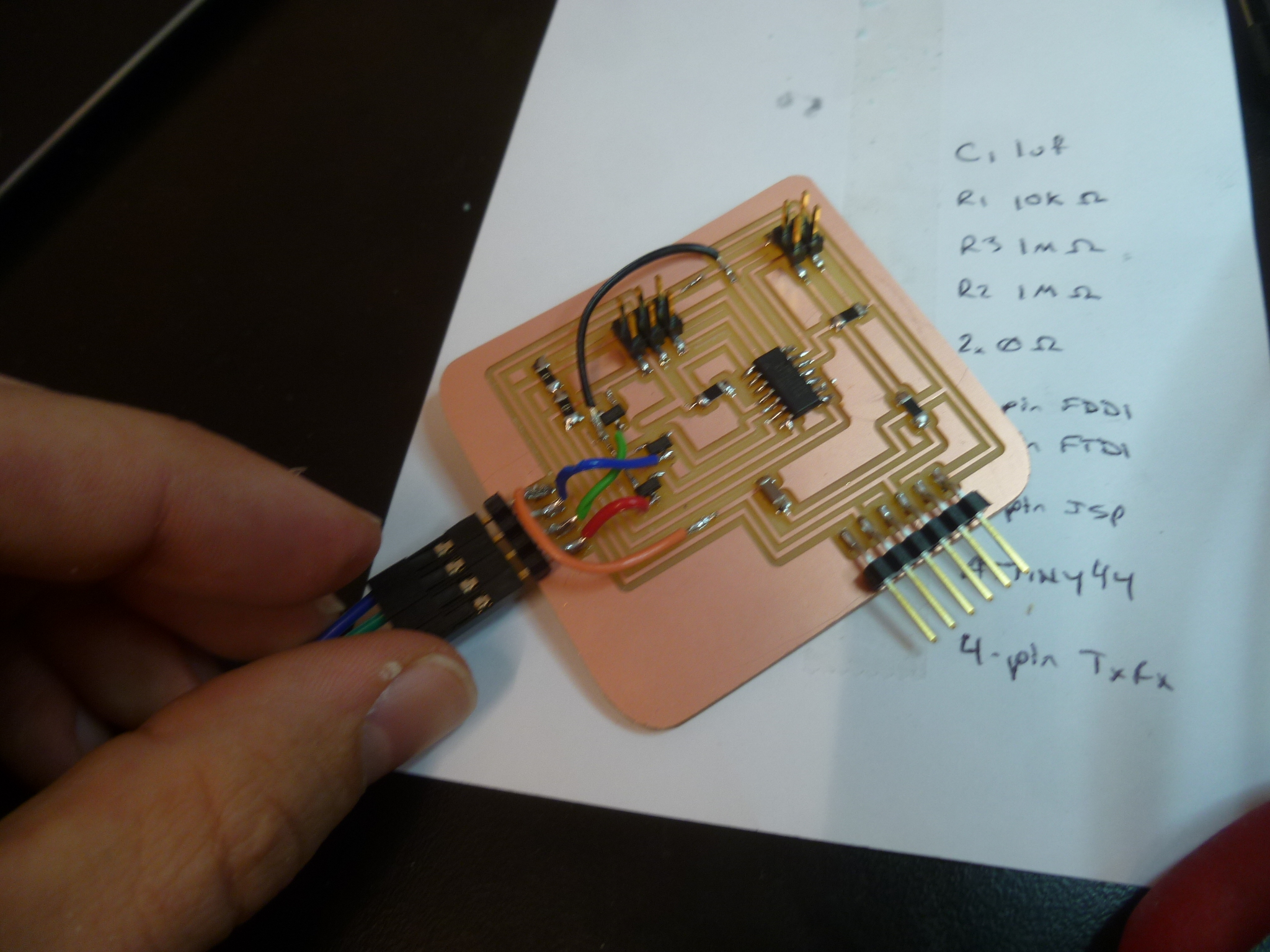
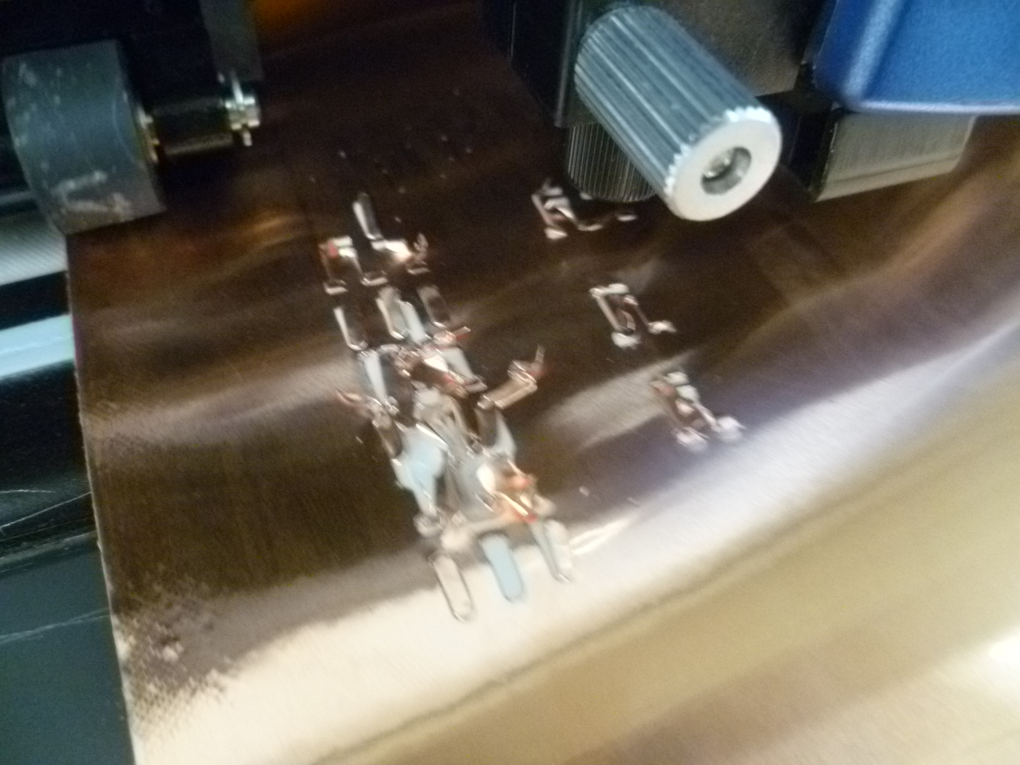
Milled on a Roland MDX-20, stuffed by hand
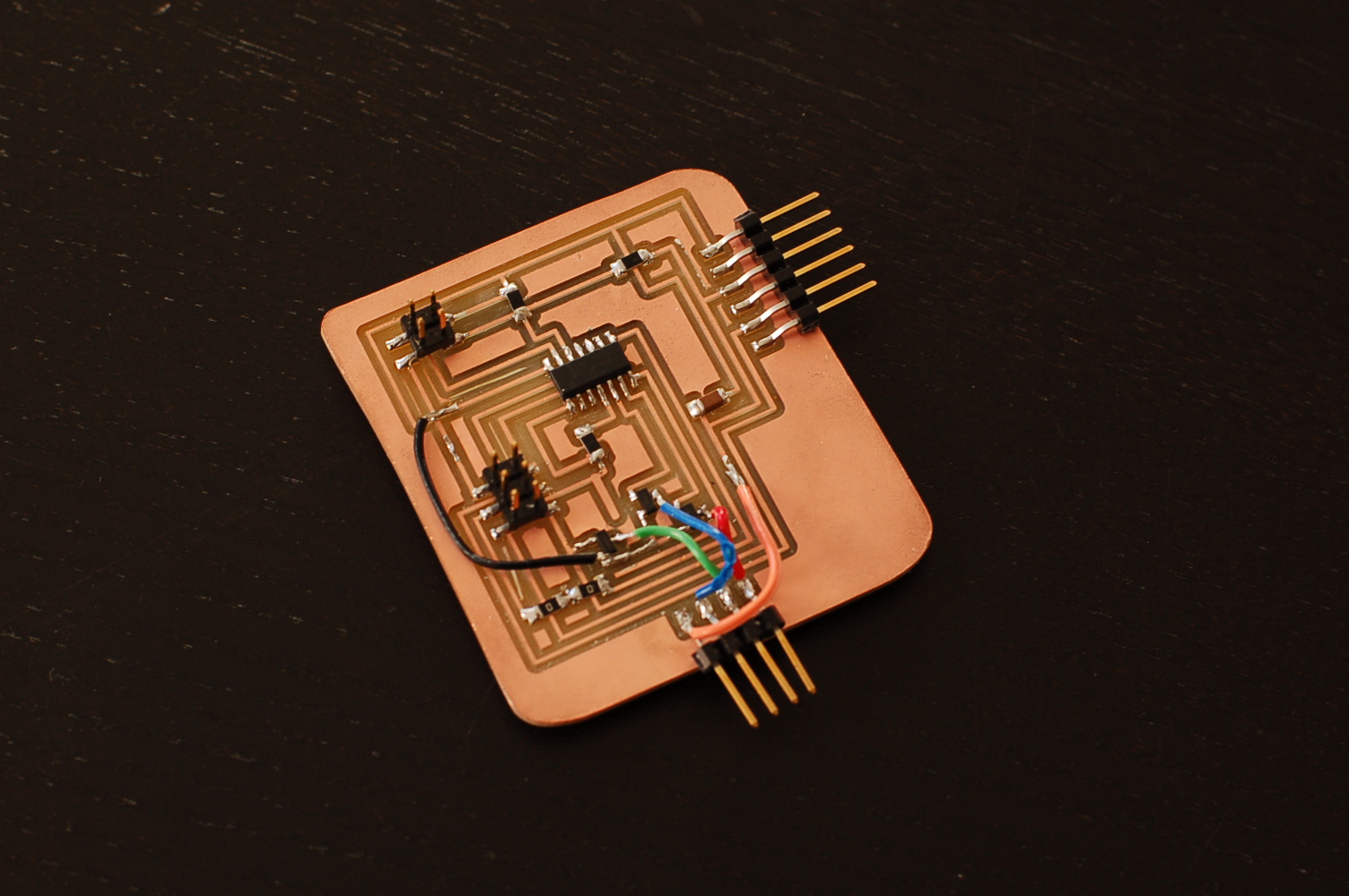
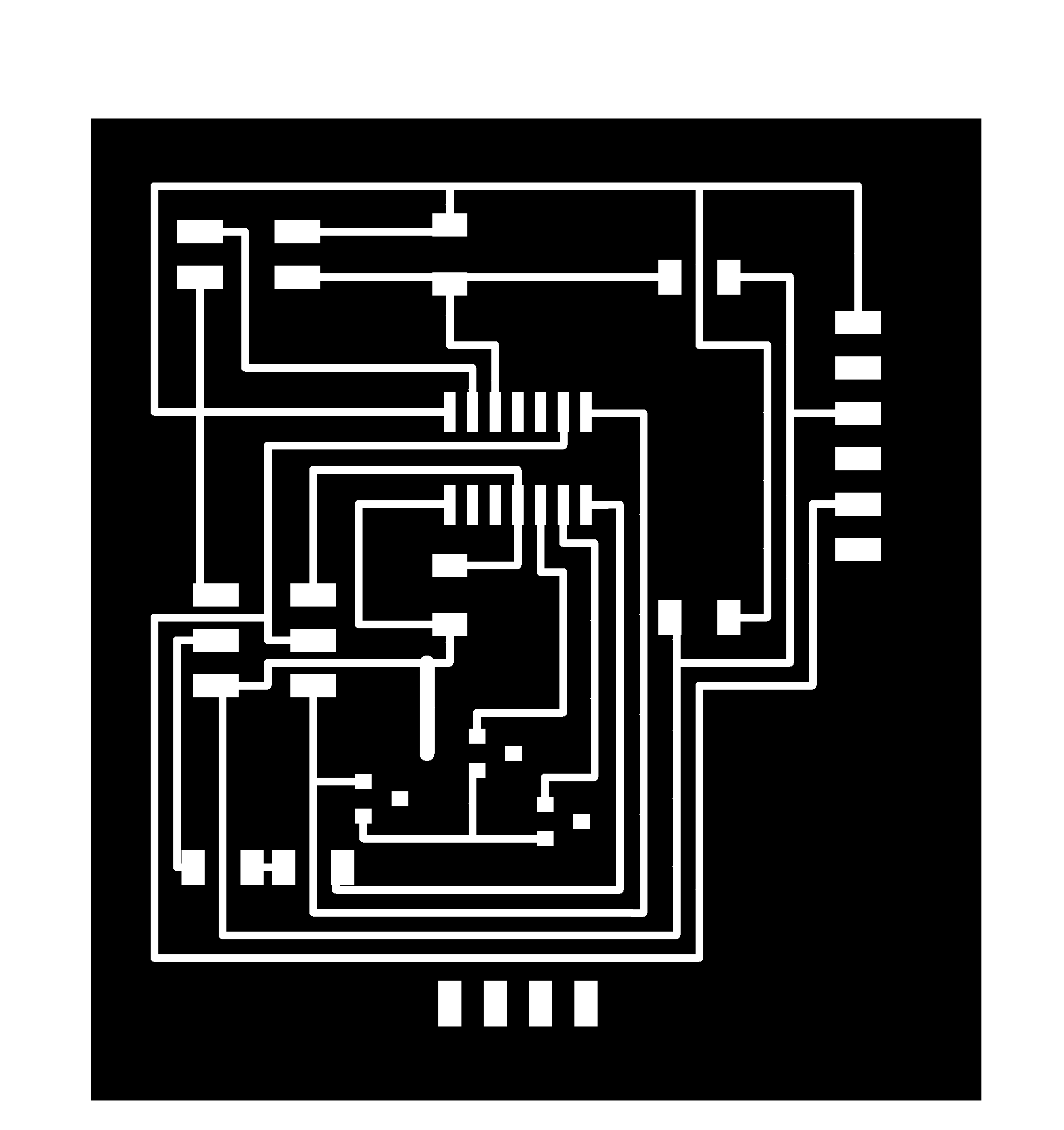
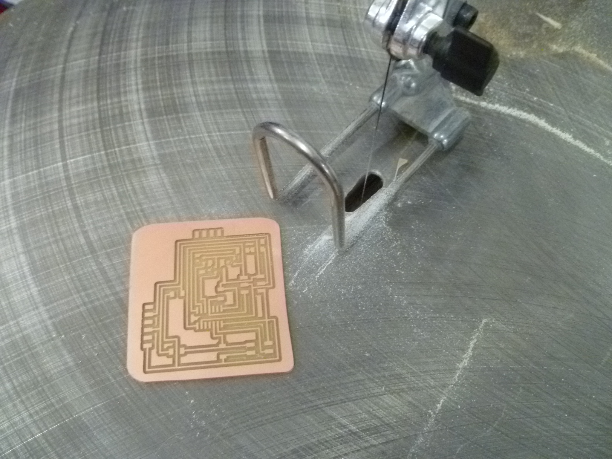
I laid out my board using EAGLE, and milled it out on our Roland MDX-20, using a 1/64" endmill for the traces. I encountered an error when I went to mill my cutout path, lost my XY zero, and ended up cutting it out using a very thin blade on a scroll saw.
The board a modified combination of Neil's Hello World TxRx and RGB boards, further modified from when I combined the two back during Inputs Week. At that point, I knew I'd want to control RGBs with step-response, and had planned accordingly. I had thought it'd be easy to lay out my final board, a simple modification of that board where the RGB and associated resistors are elsewhere. I needed to add a 4-pin header (one each for R, G, B, and Vcc), and incorporate the transistors Rob had helped me decide to use.
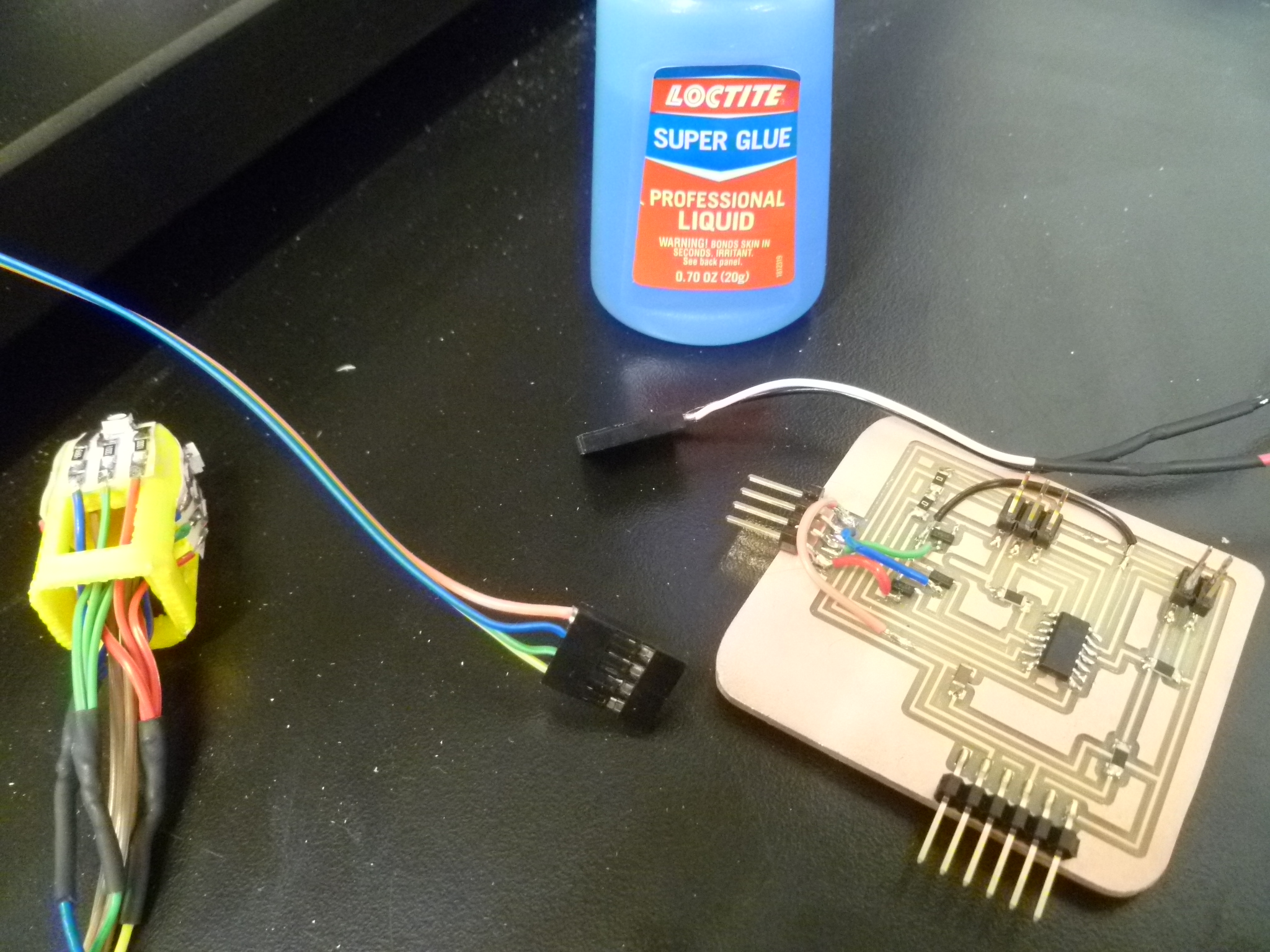
Of course, it ended up being more complicated than a simple rerouting, and I didn't have the time to make it all work cleanly; I instead just opted to use a bunch of jumpers. This is okay, it helped me more clearly identify which color was which (Vcc is the orange wire, as the traditional red was taken by the Red LED). This 4-pin header was apparently under quite some strain from the pressure of the jumpers, and pulled up off the board. I superglued it back down.
The brains of the whole thing is an ATTiny44, a shockingly complicated and capable microprocessor that you can buy for pretty cheap.
in C
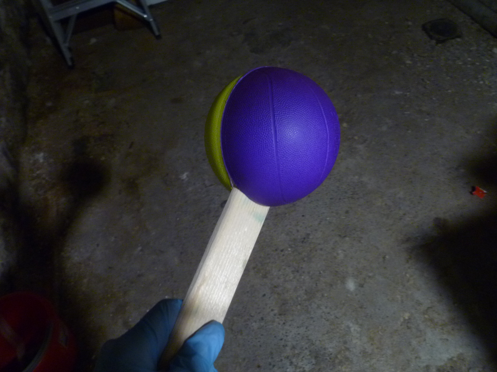
Using Neil's TxRx and RGB codes as a starting point, I first had to gain basic control of my RGBs, which I did to moderate success during Outputs Week. (http://fab.cba.mit.edu/classes/863.16/section.Harvard/people/Krasser/Week%2010/w10.html) I had many modified versions of the RGB where it looked like a certain color was stuck on, but eventually, I figured out how to fade each color in and out. Working from there, I constructed a color cycle that represented the range of star colors: Red, fade Green in to create yellow and orange, fade Blue in to create white, fade Green and Red out to leave us with the hottest stars, blue ones.

With some help from Manar, I connected my step-response data to control my RGBs, using If / else then statements based on step-response value. I figured out how to place the step-response value (srv) in between two values (e.g. "0 < srv < 10" is coded as "srv<10 && srv>0"), and fiddled around with numbers until the RGBs responded to what I was doing with the step-response electrodes. It's at this point that I figured out I was measuring the capacitance between the wires, rather than the electrodes, and did my best to remedy the situation.
After the failed attempts at shielding mentioned above, I reinserted the electrodes into the foam balls, and started playing around with values in my code, seeing if I could get the colors to respond more consistently. I made moderate progress!
I decided, for the presentation, to have it simply cycle through the star colors when the TxRx wasn't plugged in, and to switch in to step-response control when the TxRx was. It's somewhat reliable, and for now, that's good enough for me. (One fun error: when the TxRx is plugged in, touching the metal pedestal affects the reading. There's some odd electrical interference going on that I don't quite understand.) Debugging can be done in due time. My ultimate goal is to figure out how to map the step response data to smoothly change the color using PWM (pulse-width modulation), but because coding is easy to alter at any time, it got bumped down the priority list.
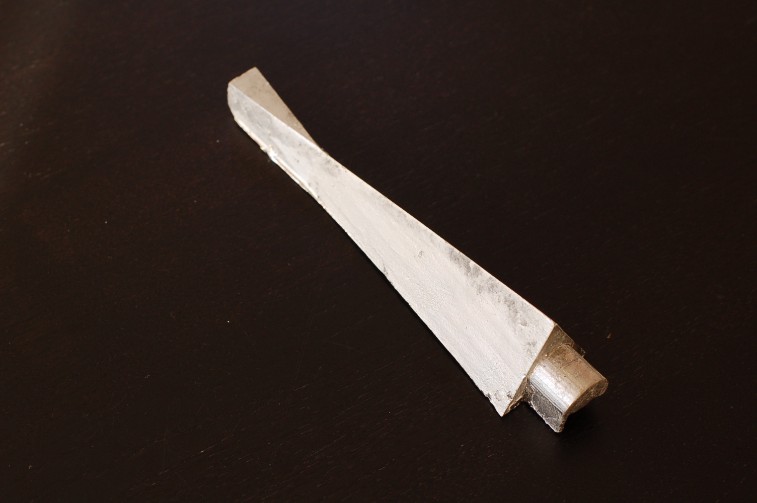
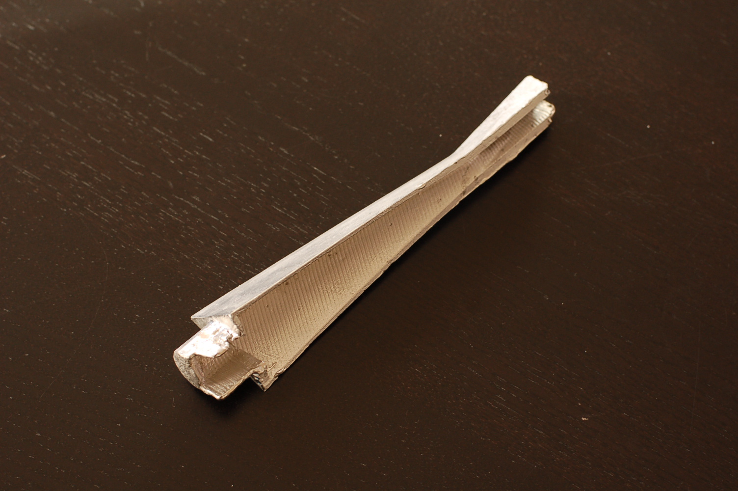
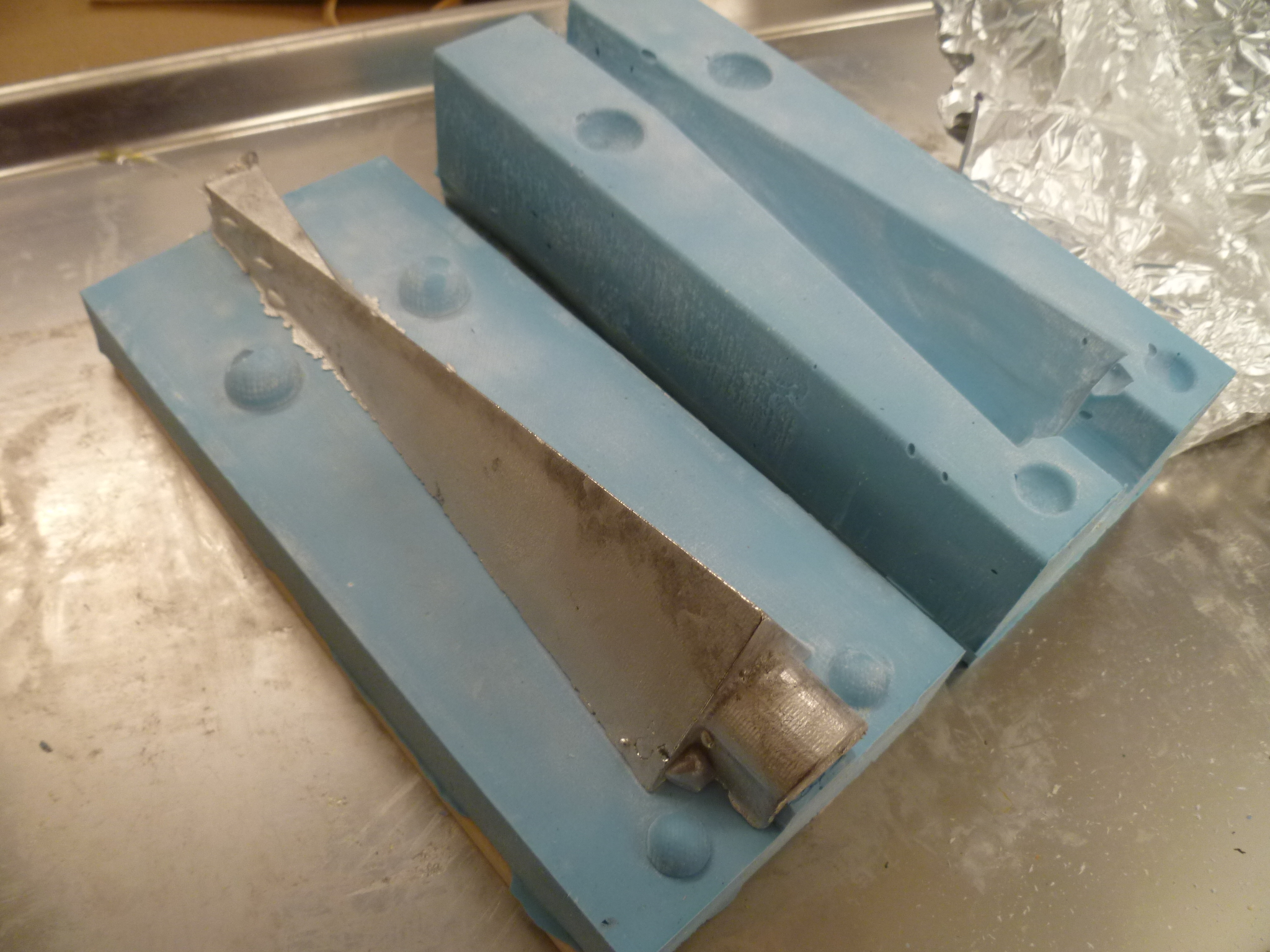
Tin-Bismuth alloy cast in an Oomoo mold
In order for the pedestal to successfully hold the star, it needed to do a number of things:
1. Anchor solidly to the baseboard.
2. Support the weight of a 5.5" sphere of silicone
3. Look awesome
4. Be hollow, to allow wiring to run through it
5. Have a solid purchase on the silicone star
6. Stay perfectly centered while silicone star is being poured into mold
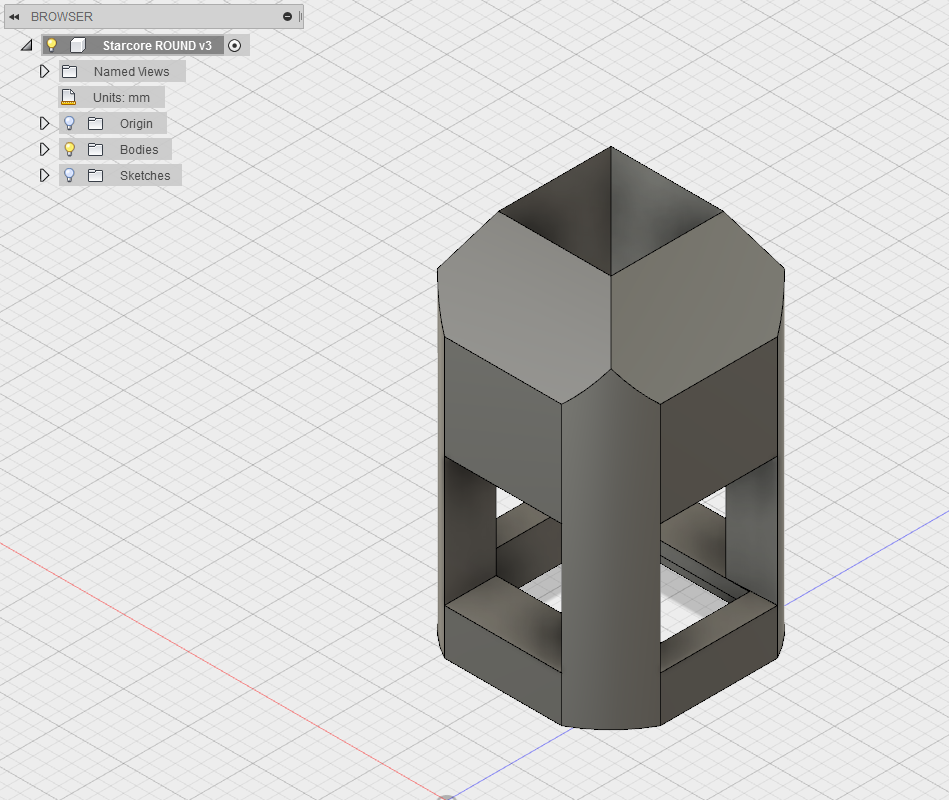
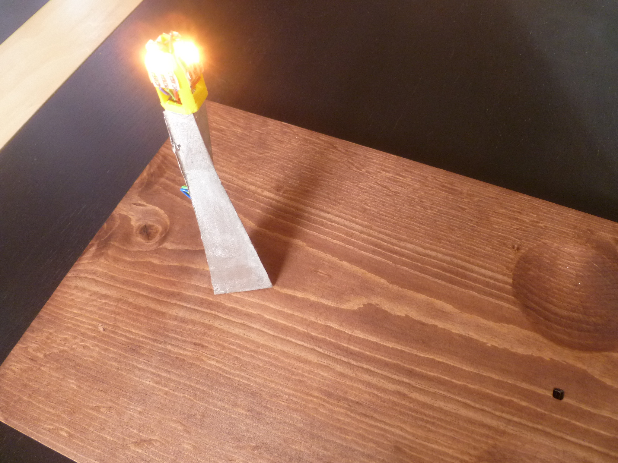
I was going to make it out of a composite or 3-D print it, but I became concerned about the strength and finish texture, and ended up deciding that casting out of a tin-bismuth alloy was the best option. After building many versions of it in my head, I arrived at a relatively simple final design.
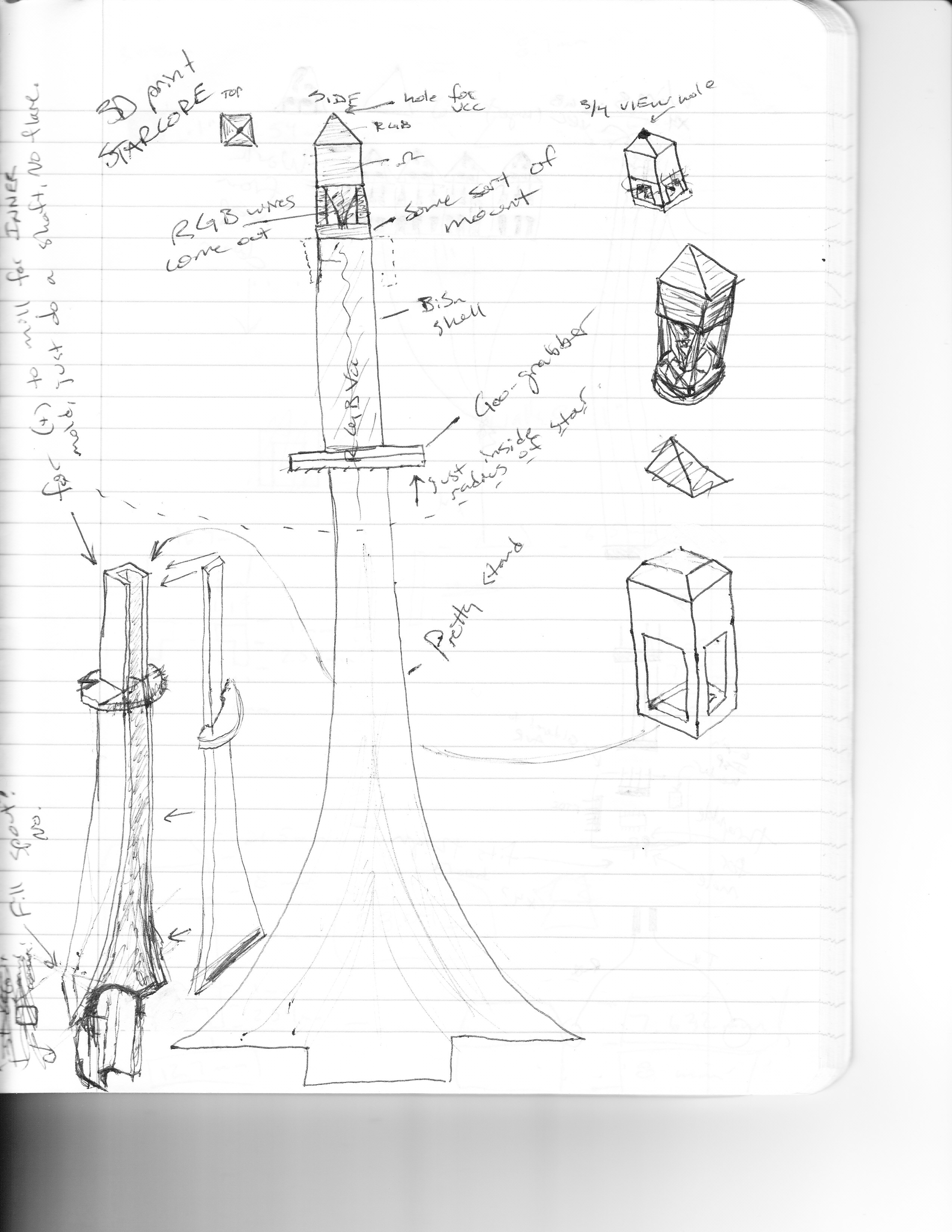
I had considered swoopier things, and flanges or ribs to help it grab the silicone, but I was happy with the final design, and it ended up being pretty straightforward to make in Fusion 360: four profiles lofted together: A D-shaped post, a triangular base, a smaller triangle where it entered the Star, and a square on top, to hold the 3-D printed, LED-bespeckled Core.
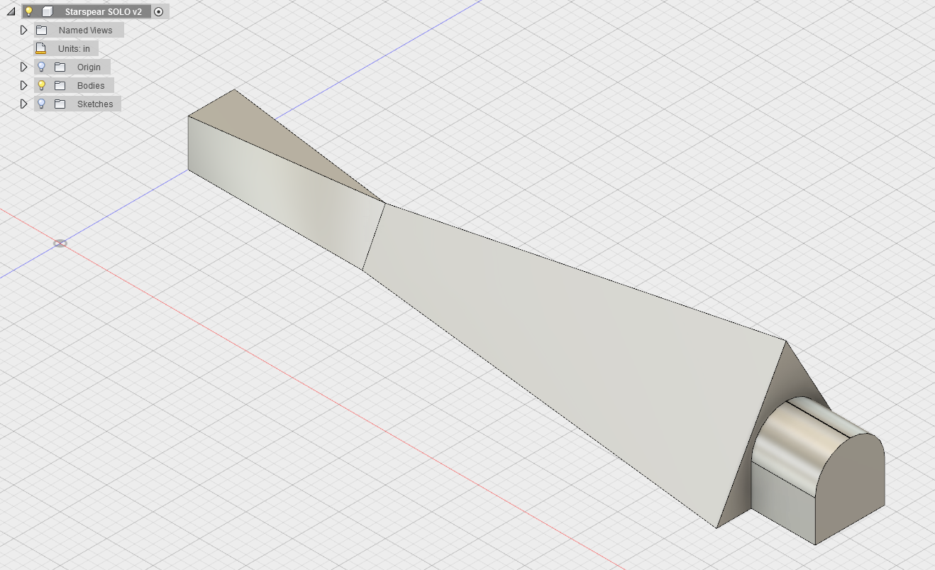
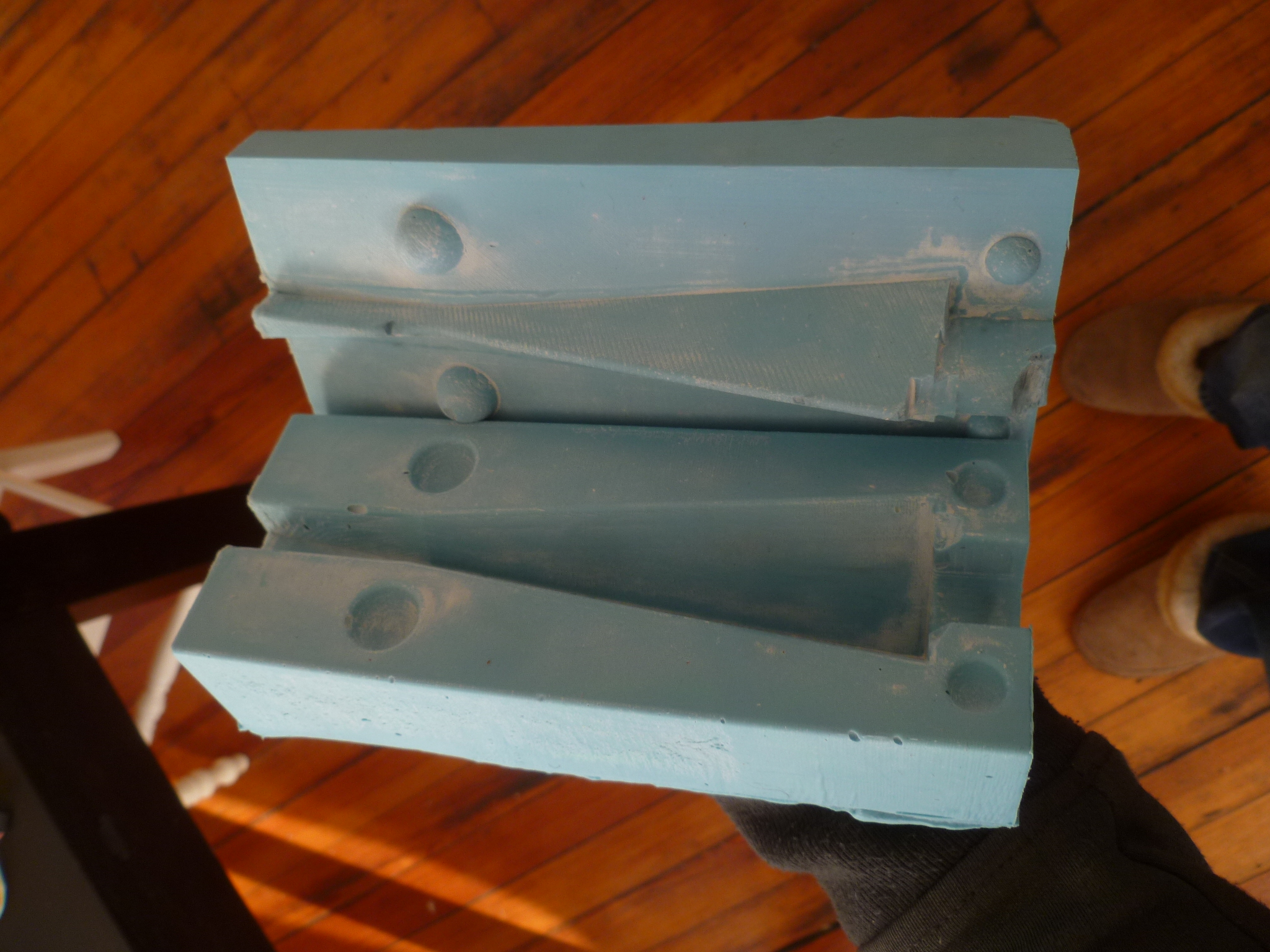
The design was relatively easy. I knew it was going to be milled out of a 1.5" x 3" x 7" brick of wax. (I could've done another size, but I didn't have time or effort to spare to melt and make a different size block, as I had during Molding and Casting Week.
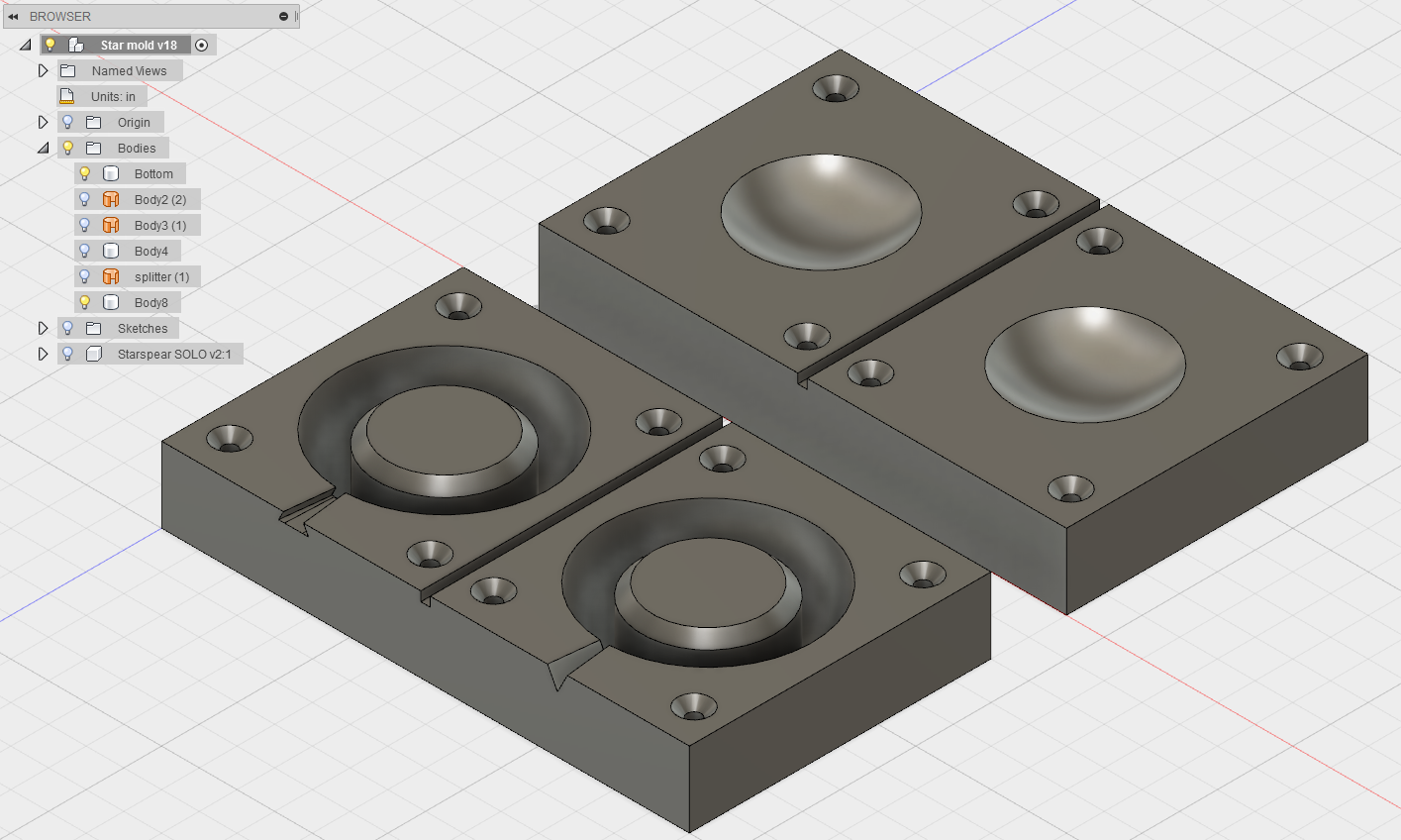
When you're designing something that's going to be cast, you're not actually designing the thing itself, you're designing the mold FOR the thing. And those are not the same thing. Because I didn't want to cast a solid piece, I needed to figure out a two-sided mold that would only create the shell of the thing. I had considered casting a 3-sided piece, but realized it'd be much easier to just have an open-backed pedestal. This would also make wiring pretty easy to access.
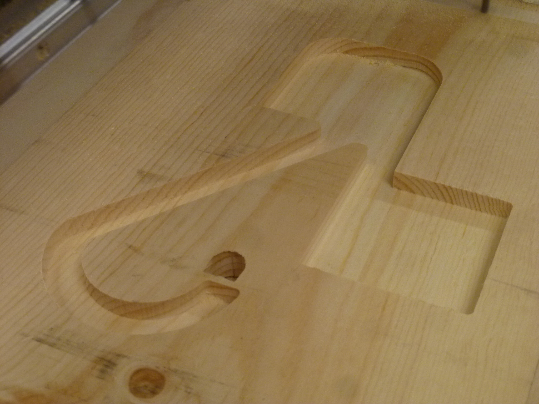
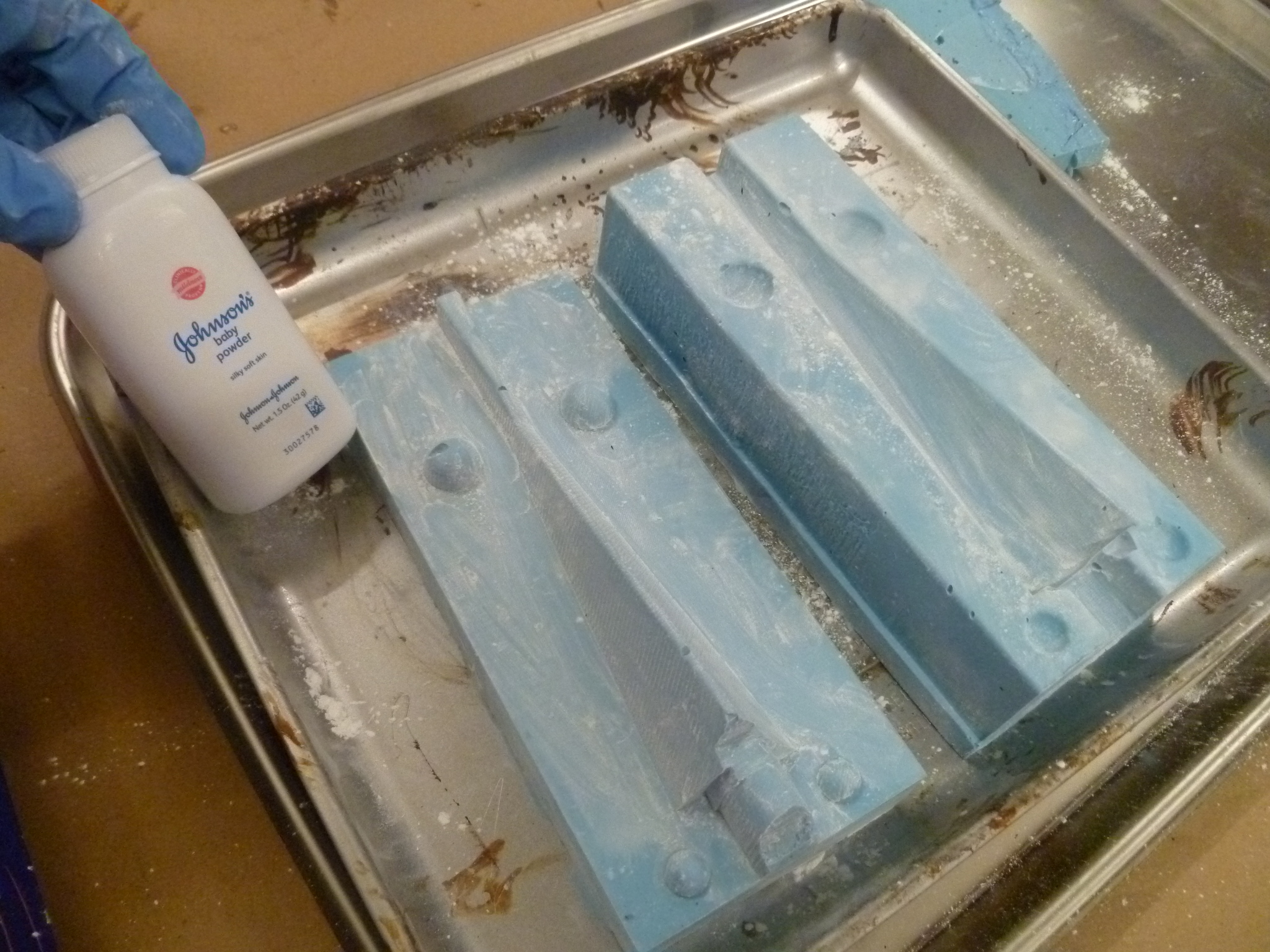
Designing the mold for the shell was interesting. I designed a front-facing positive, the shape and size of the piece the user would actually see. This got milled out of wax. I used a .25" downcut endmill, which made an absolute mess of the wax.
I figured the finishing pass would make quick work of it, but it seemed to gum up the 1/8" finishing endmill.
I ended up sanding the wax positive to smooth it out. I poured Oomoo over it, which made a negative. This negative would be filled with the tin-bismuth to create the positive.
To make the inner portion of the mold, I just redrew each profile .1" smaller, and milled out a negative of that in wax.
When cast in Oomoo, this piece would, in theory, sit .1" away from the other half of the mold. I added registration hemispheres to make sure the two sides lined up exactly. Success!
However, I forgot that I only wanted one side of my mold open for pouring, and had to seal the other end (the bottom) with silicone glue. This left an ugly, uneven top after casting. This had a mildly adverse effect, discussed below.
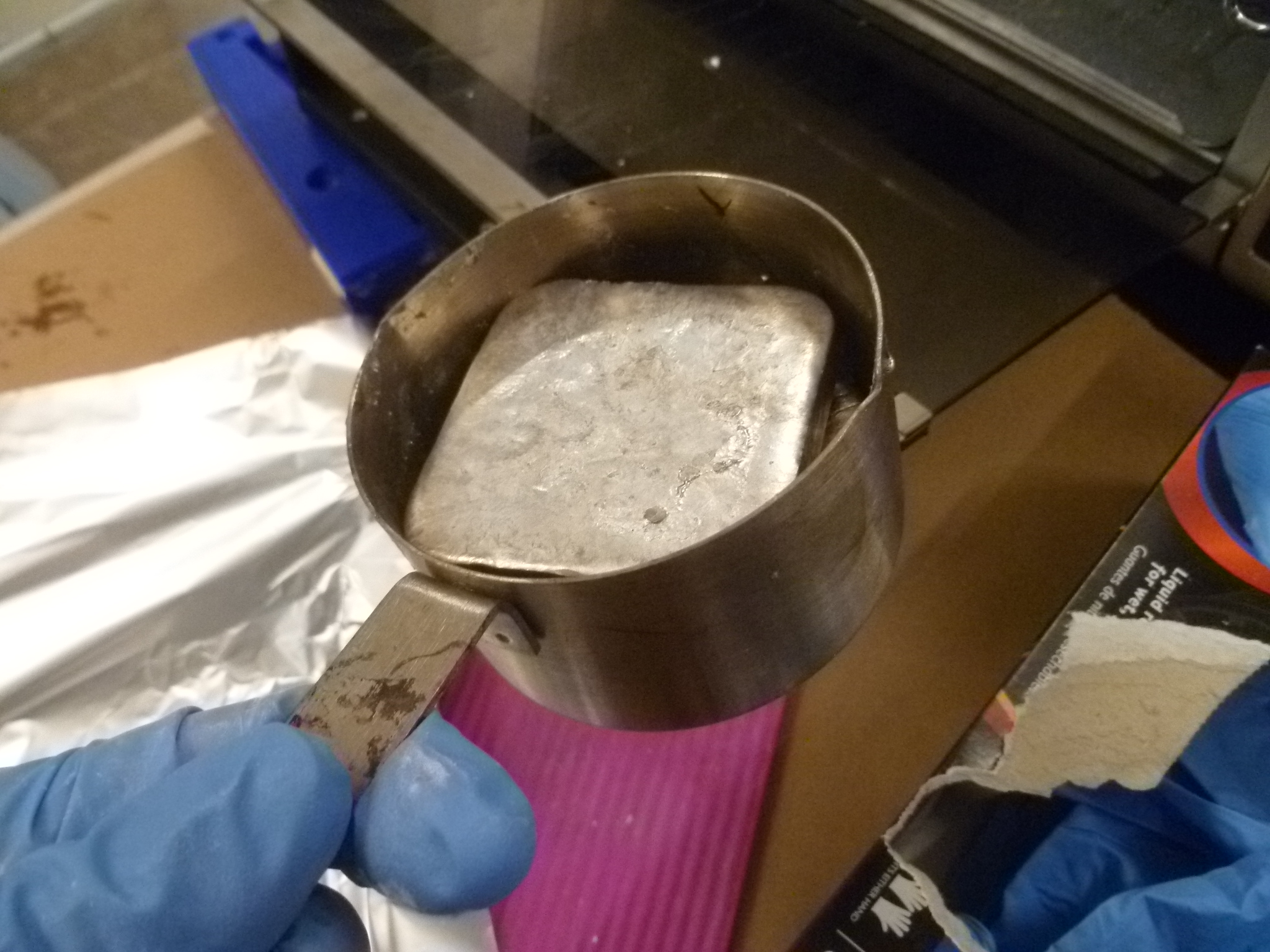
Casting was fun! I melted two ingots of tin-bismuth in the toaster over at 400 degrees F. In the meantime, I coated my Oomoo in liberal amounts of talc, to help the metal wet the surface evenly; this prevents an ugly, pockmarked appearance.
I walked through every step very carefully, ensured that the mold was properly lined up and constrained, and poured. It took way less than I was expecting!
Overall, I was very pleased with how the casting turned out, but the rough top was a bit of a bummer. No one would ever see it, but the RGB LEDs were mounted on a 3-D printed core that was designed to snugly fit over a square top. I had to use a soldering iron to melt and smooth the top, picking out bits of blackened silicone with tweezers.
I also (carefully!) smoothed out some edges, melted away some blobs, and sharpened the angles where the base of the triangle needed to sit flush with the board. Which it does! I'm pleased with the fit, though not 100% sure how best to secure it. I might just epoxy the damn thing, or leave it unattached, a friction-fit only.
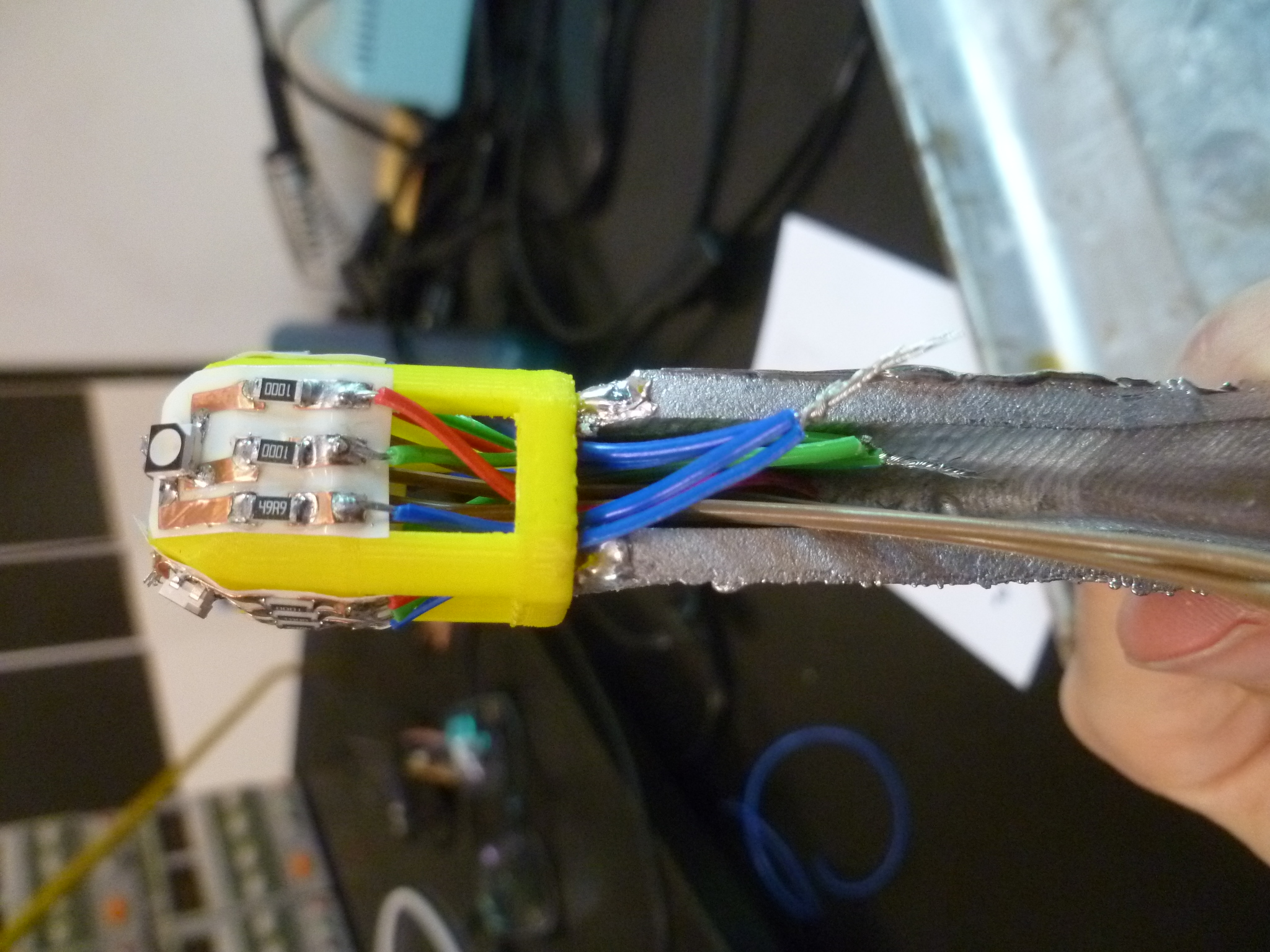
RGB and resistors soldered to vinyl-cut copper traces suck on epoxy film, stuck to a 3-D printed base
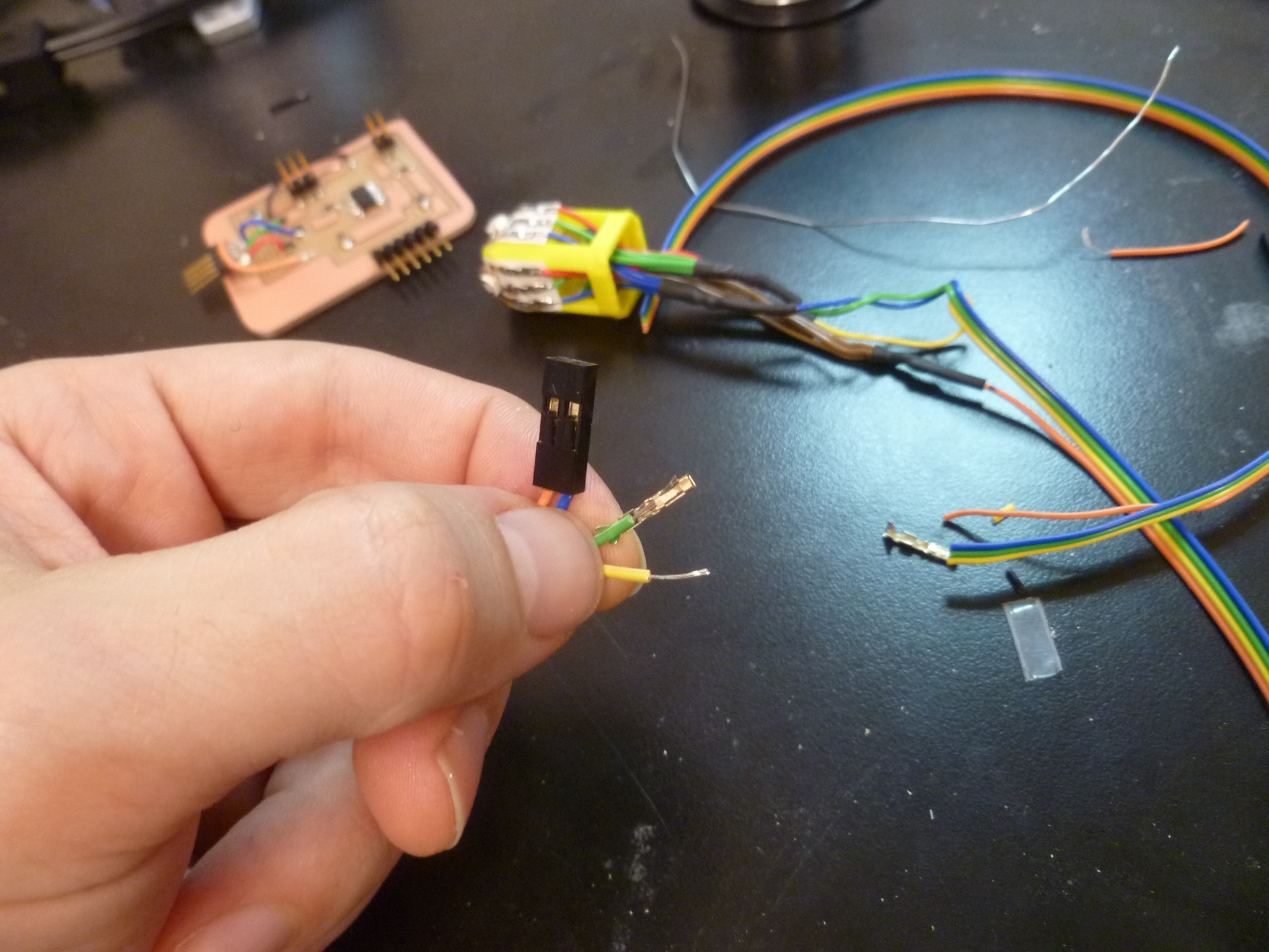
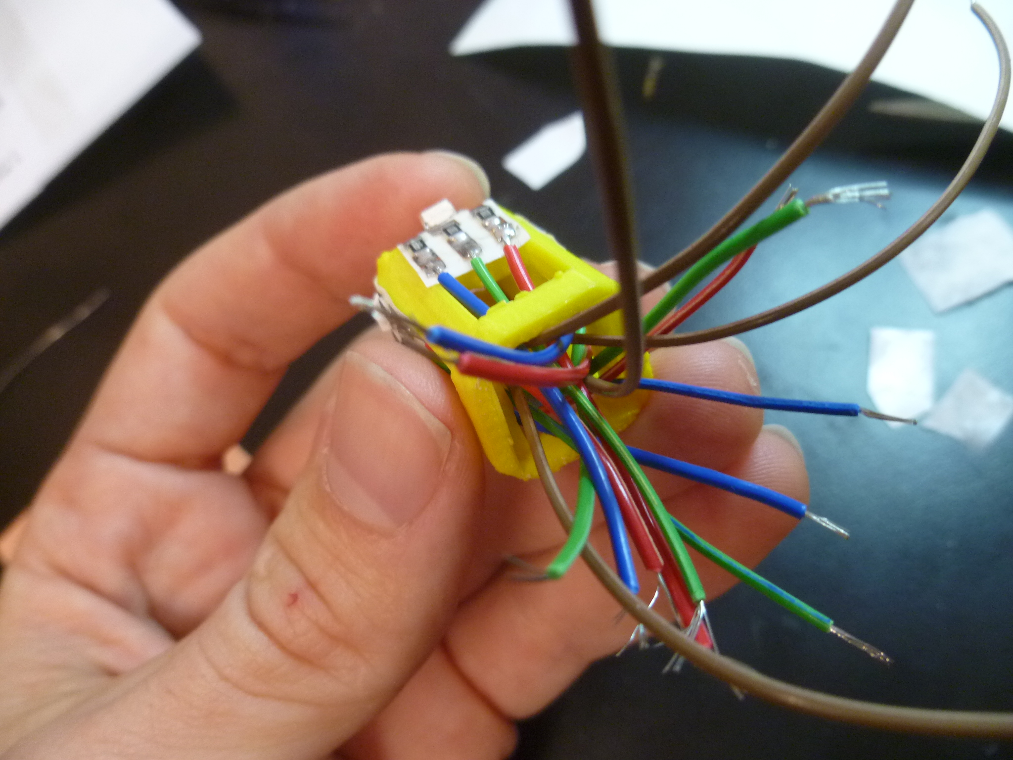
The wiring running up through the pedestal to the RGB LEDs was, again, non-trivial. Each wire had to split into four wires: an R, a G, a B, and a Vcc for each of the four LEDs.
I built it from the top down, so that's how I'll describe it.
The LEDs and resistors are soldered onto copper traces cut out on our Roland vinyl cutter: force 35g, speed 1 in / sec. Too much force / speed made a mess.
Those traces were then stuck onto an epoxy film, which would handle the heat of soldering.
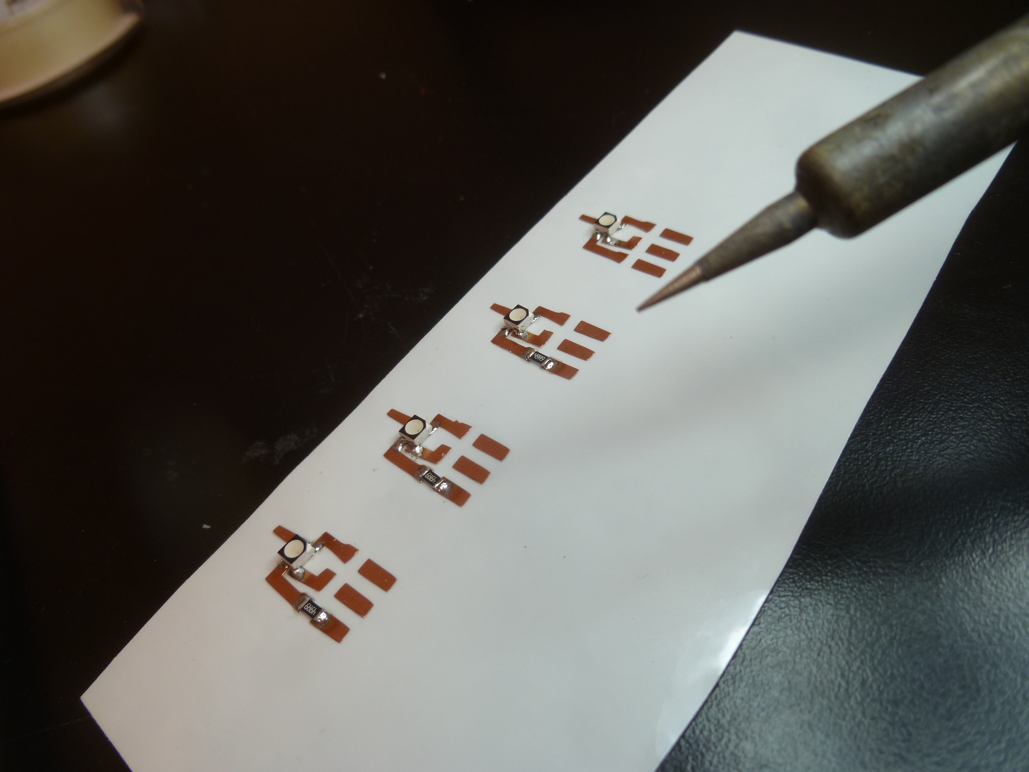
Soldering onto these traces was slippery, as it seems the intense heat melted the glue joining the copper to the epoxy. As such, I wouldn't recommend vinyl-cut traces for any small, intricate boards. I also soldered each wire that would be needed (an R, G, B, and Vcc for each LED) on to the traces.
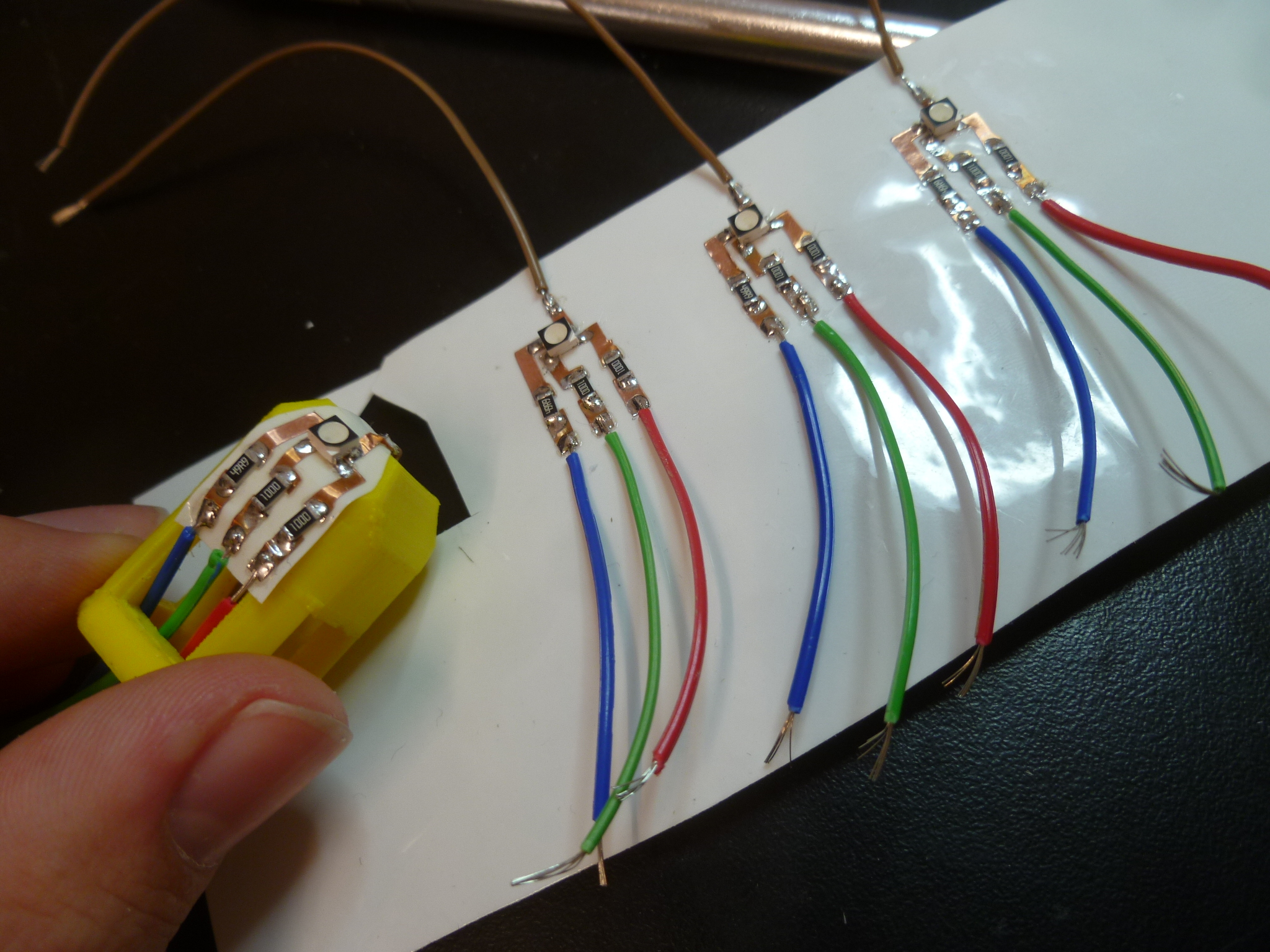
Next, I cut out and stuck these circuit stickers on my 3-D printed core, carefully guiding the wires through their respective holes.
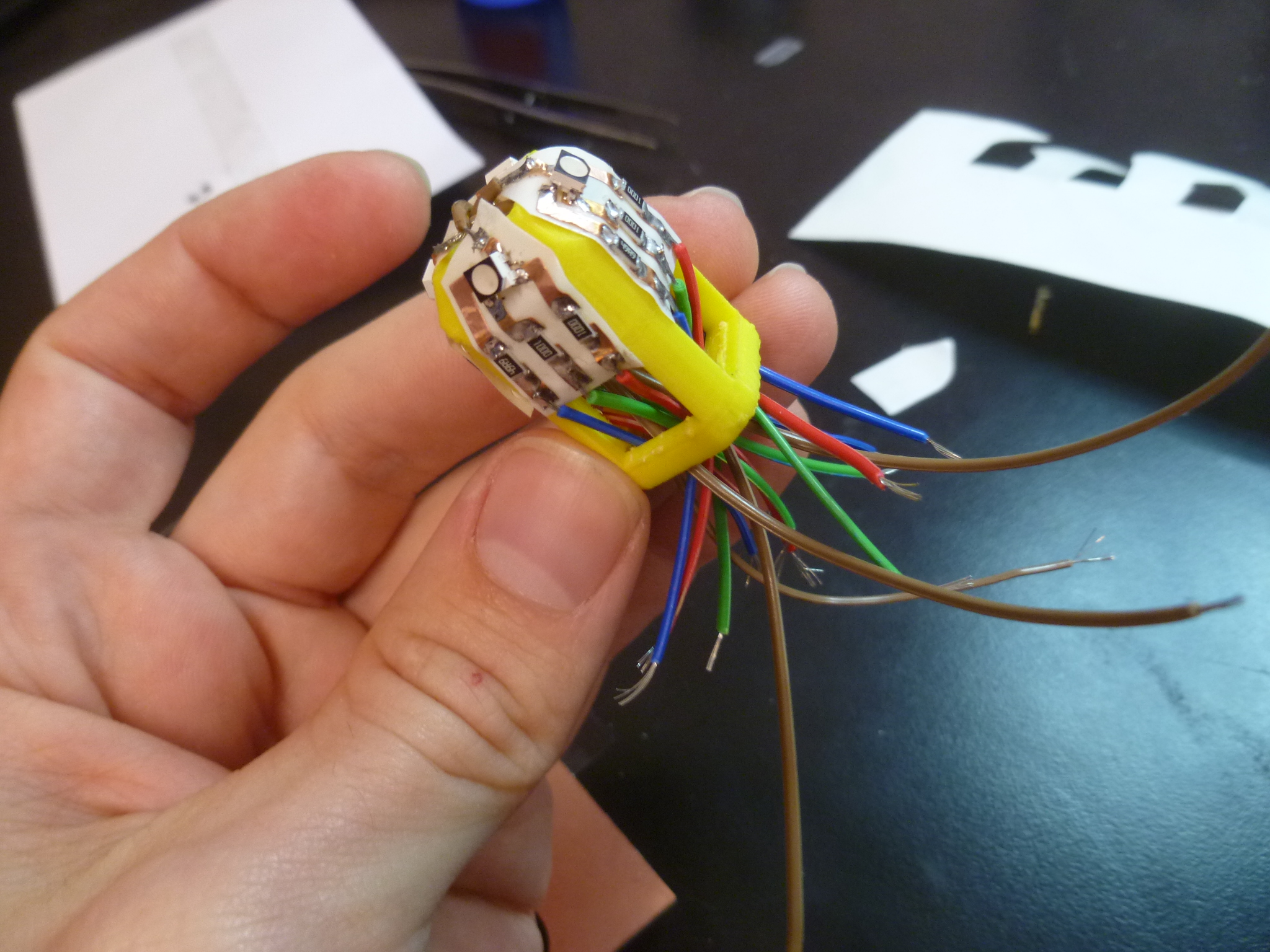
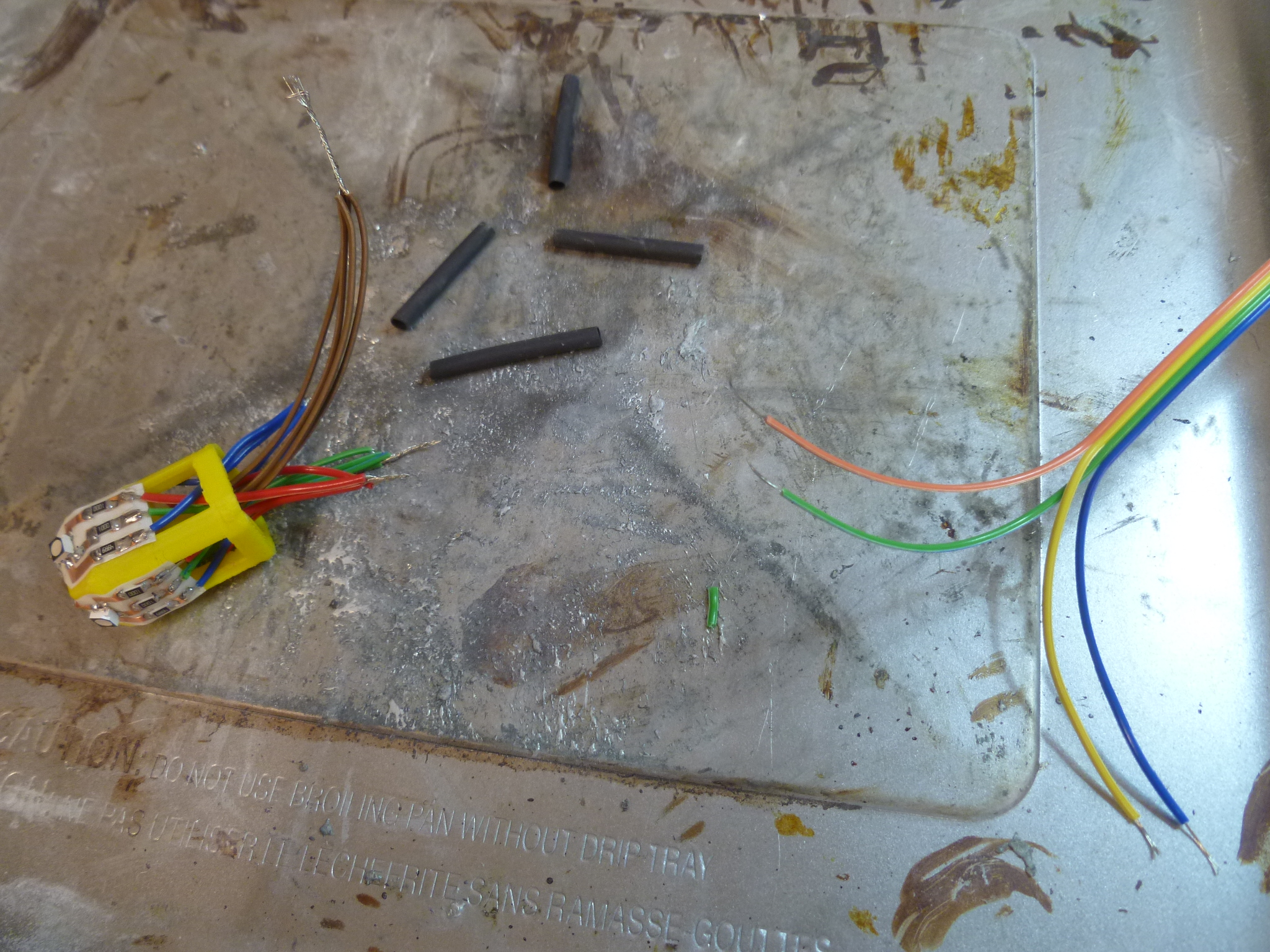
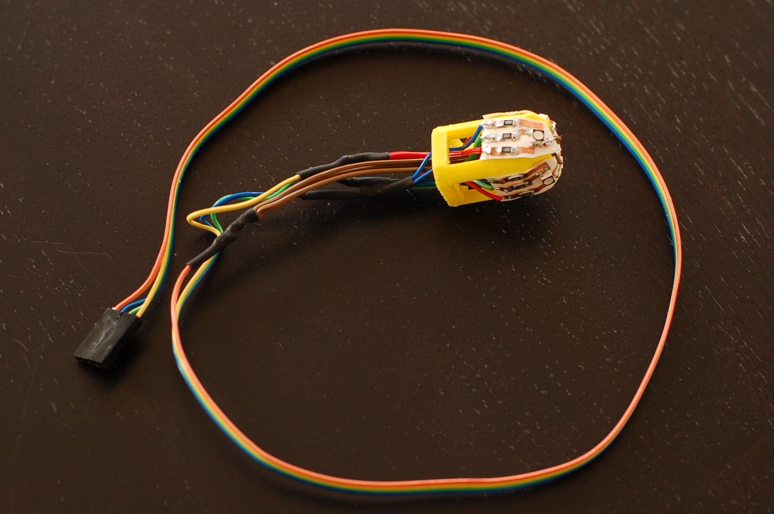
After some quick organizing, I twisted the four Reds into one Red wire, the four Greens into one Green, etc. (I worried about the thickness of a bundle of 12 wires inside my narrow pedestal, and opted to reduce the number of wires to four as close to the top as possible.)
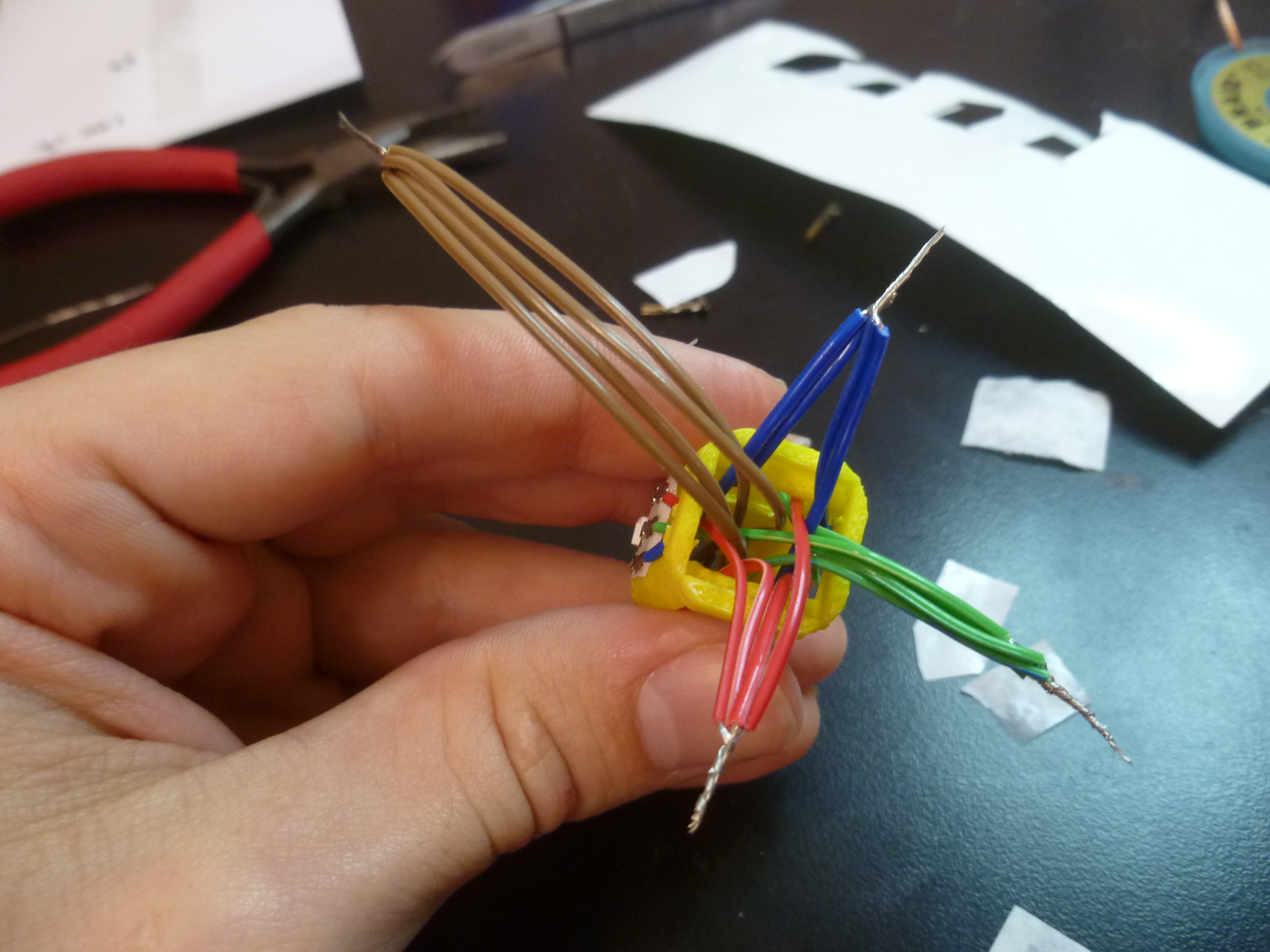
I then soldered these to the appropriate wire coming from the AVR board, and sealed the joint with heat shrink. This soldering was a little tricky, and involved pinning the twisted wires against a pool of solder with my iron, adding more solder, then keeping the wires pinned somehow while removing the heat.
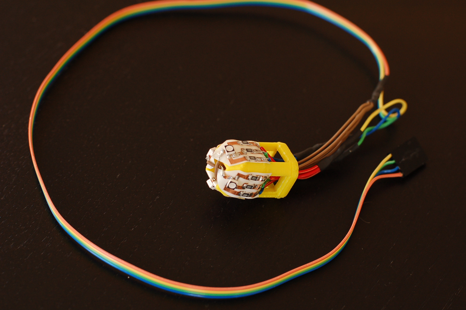
The first design of my core was a nice print, in white (a reflective color), everything felt solid, the holes were a good size to work with, etc.
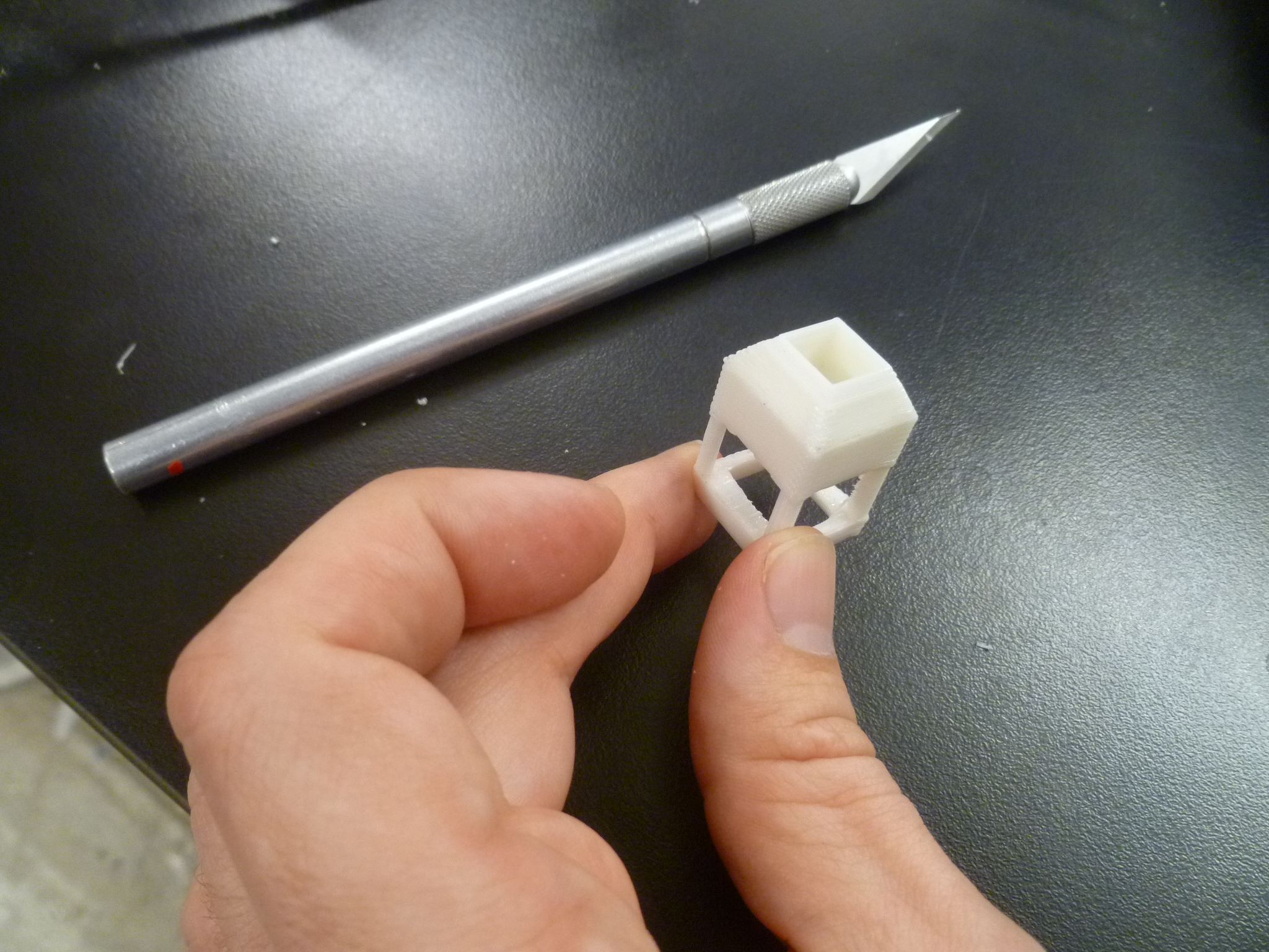
But because of some issues with molding and casting the big star, I had to redesign the core to fit through the narrow neck of a glass beaker. (More on that below.) And of course, my first design was just fractions of an inch too wide. Figuring out exactly how narrow the beaker got was a challenge, solved with a carefully angled piece of wood.
I redesigned the core accordingly (first, with a lazy slice-job that left legs too thin to print, then a more purposeful design with stronger supports and wide enough openings to fit wires through.)
Inevitably, there was a problem. The printed core fit fine, but with the added width of the resistors … too wide. Rather than modify the core again, I opted to get in there and sand the neck to be fractions of an inch (and I do mean .05" or so) wider. I was going to use a file, but Daniel in the Harvard shop told me sand paper is actually harder than steel, and a more effective choice. It worked!
Which brings us to ...
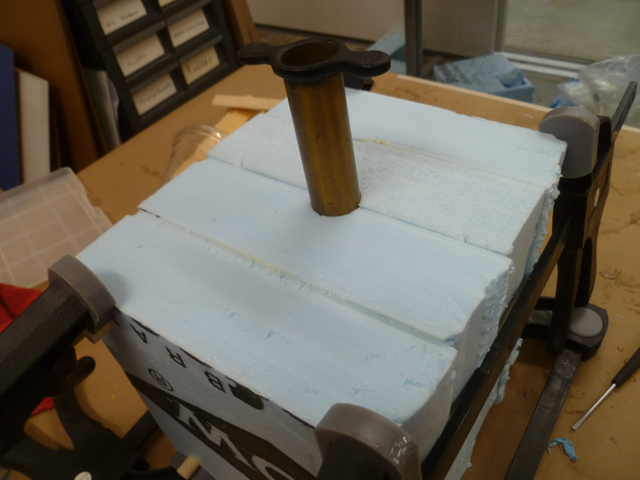
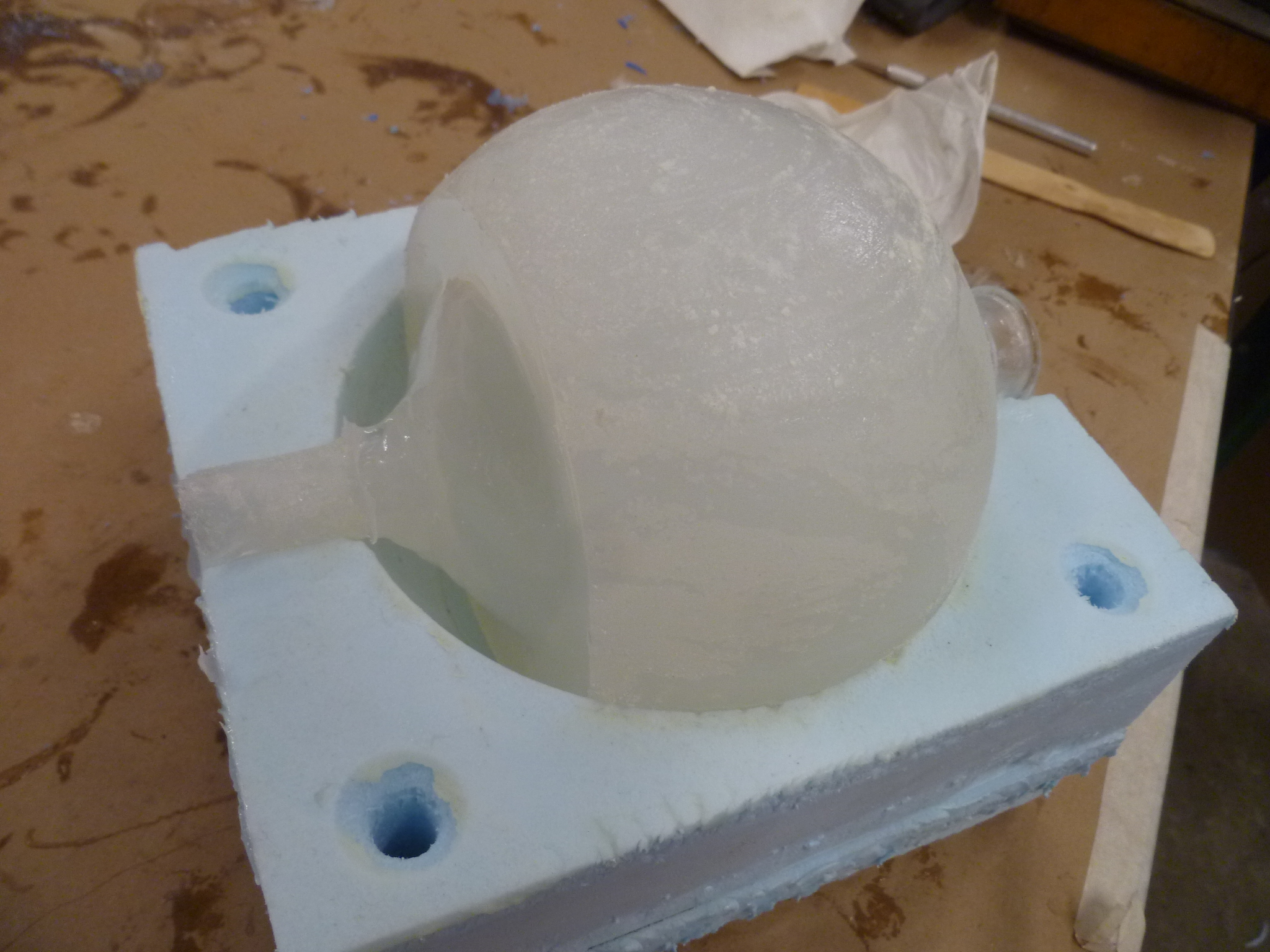
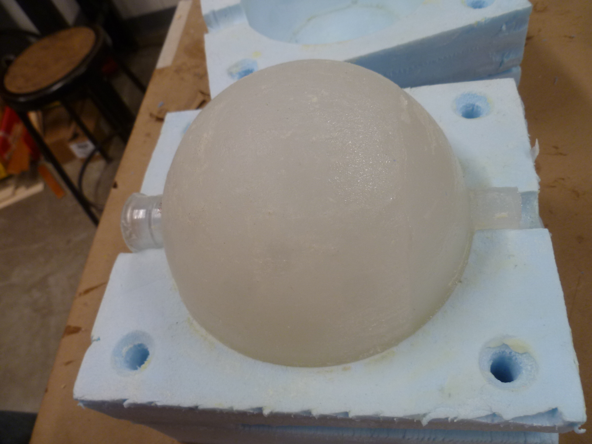
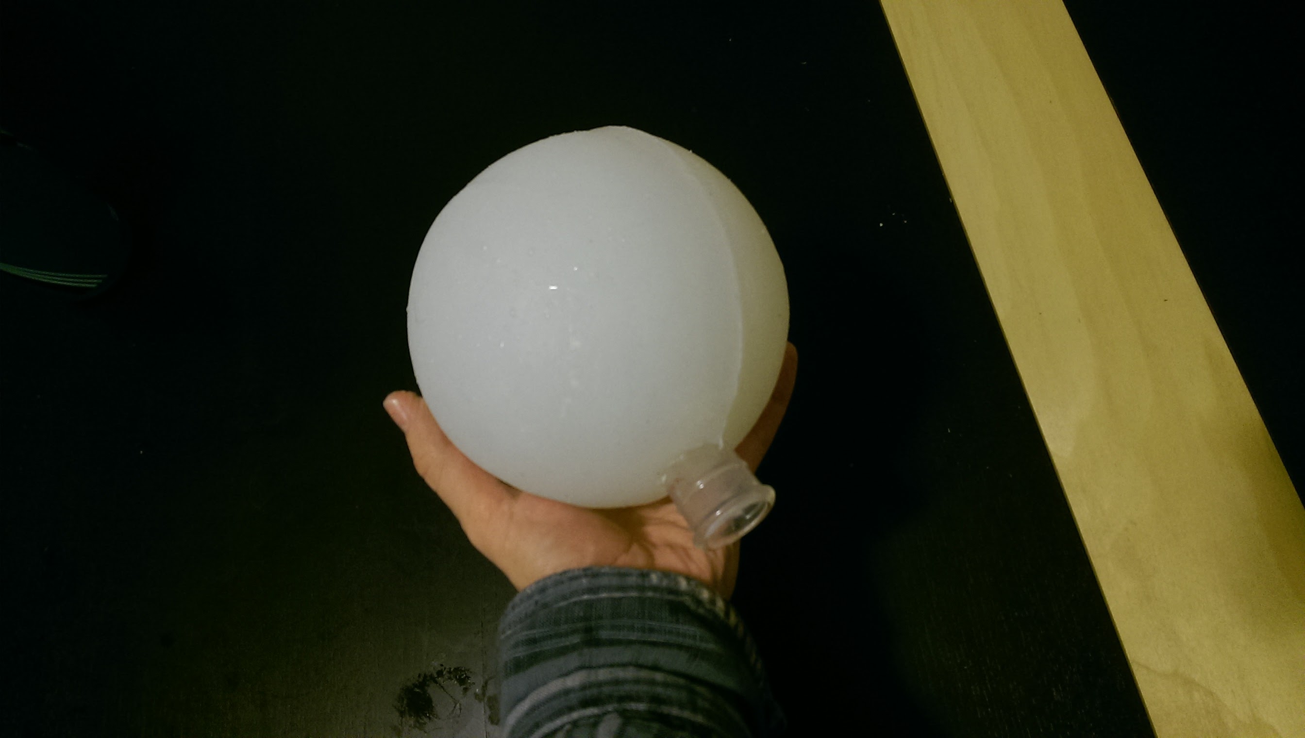
A 500 ml spherical glass beaker encased in 1" of translucent silicone, cast in a foam mold
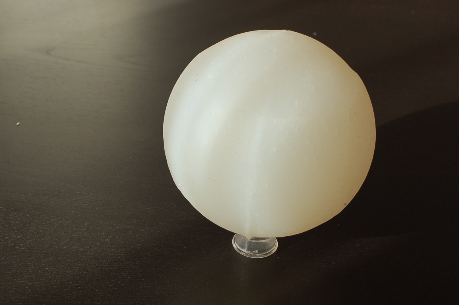
If you had told me when I started that the most complicated piece of my project to make would be a 5.5" sphere, I would've said "A sphere? Really? What's so hard about a sphere?" Turns out, it wasn't the shape, it was the size.
I was originally just going to cast a solid 5.5" sphere of silicone around my pedestal and LED-bedecked core. Simple and straight forward. But, of course, there were complications. 5.5" seemed like the right size, given the constraints that it needed to be appreciably larger than a 4" atom, and to look proportional atop a pedestal limited to a 7" block of wax (including depth below wood and embedded within the star). 5" was too similar to my eye to the size of the atoms, and 6" dwarfed the pedestal. So, 5.5" it was.
Talking with Rob, and a few other people in the lab, I got the sense that a solid 5.5" sphere was a bigger thing to cast out of silicone than most (sane) people would consider reasonable, and that I should seriously consider some sort of hollow core. He helped me think through other options, like slush-molding (where you keep the mold in motion, rolling the material around the inside of the mold until it sets, creating a shell). I was skeptical that a silicone shell of that size would grab the pedestal effectively, and be able to support its own weight without collapsing in on itself. (As much fun as it might be to model a black hole, that's another project for another time.)
However, what solidified my decision to seek a hollow core was when I tested how well RGB light cut through MoldStar, the translucent silicone. Using a trial piece that was about 3" thick, it looked to me like the light propagated through only about 1.5". Okay, fine, I was already worried about light making it all the way through (see earlier discussion with Rob re: power and LED brightness), so I went home and tried to figure out how to get a solid, translucent core in there.
Easy. We had translucent filament for our Makerbot. I'd 3-D print a translucent 3.5" sphere, leaving one inch of silicone all around. I'd design some spokes into the center of the sphere, so it would attach and center itself to the starcore mentioned earlier.
Of course, our Makerbot had been acting up, and couldn't be trusted to make it successfully through even a small print, much less two 3.5" hemispheres. I didn't bother designing the print. Our FormLab printer, which could also do translucent, was out of service. And our Ultimaker and 3D Wox (the most reliable printer in the lab) wouldn't take the translucent filament. Because of course they wouldn't.
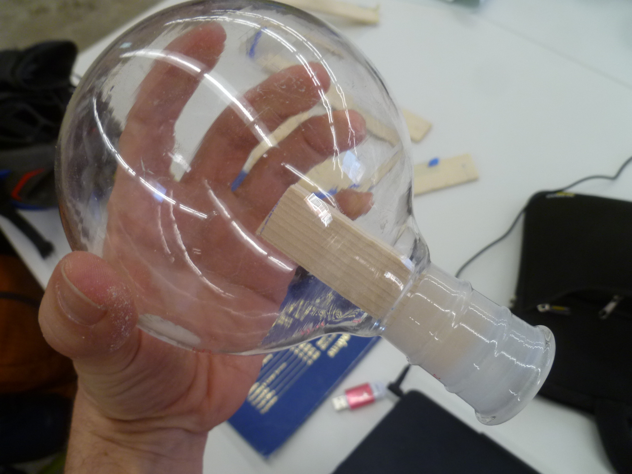
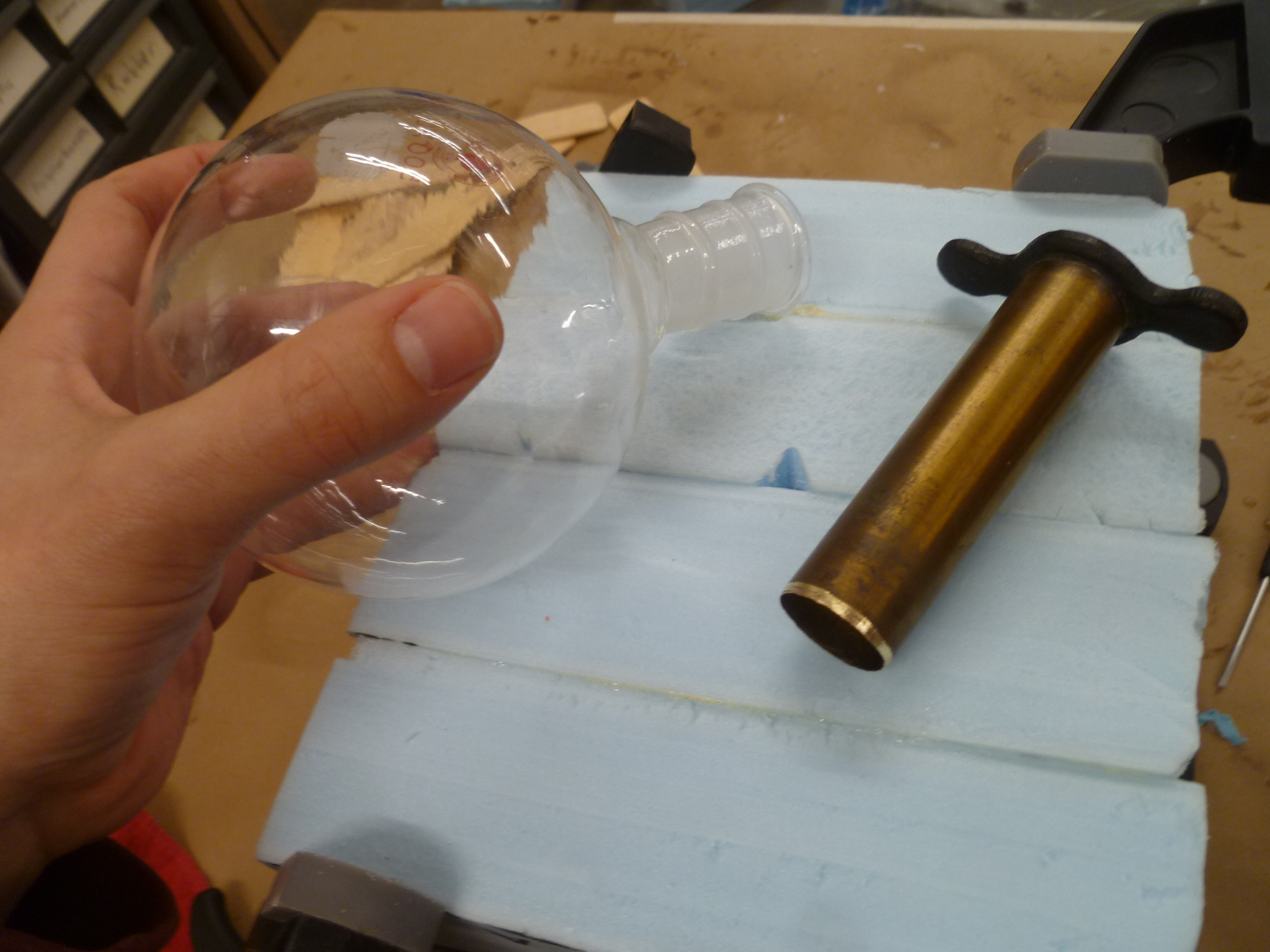
After a panicked morning trying to figure out how to form my own translucent core to live inside silicone - could I slush-mold an epoxy shell? - Rob arrived with a potential solution: a vase with a nearly spherical, 3" bulb on the bottom. However, it had a very long neck, so we approached Daniel about how to cut the neck to size. He was hesitant to cut glass, and led us on a scavenger hunt into the annals of the Harvard chem prep room, where, amongst ancient-looking chemistry equipment, I found a 500 ml beaker, a spherical one 3.5" across with a stubby neck on it. Perfect.
It wasn't actually perfect, of course. That neck, inevitably, was slightly too narrow for my extant 3-D printed LED-studded starcore, as mentioned earlier. Also, the neck would end up sticking out of the bottom of the star, killing the imagery I was going for: a silver shard launching into this glowing orb. Instead, it would look like a balloon-butt made out of frosted glass. I wasn't thrilled with the aesthetic compromise (I did think of solutions, including moving the stem around to the back, 3-D printing a scaffolding to reach in to the sphere, and wiring running along to the pedestal, now encased in silicone rather than inside the neck of the glass beaker), but I preferred an extant final product to a perfect one. So the beaker it was.
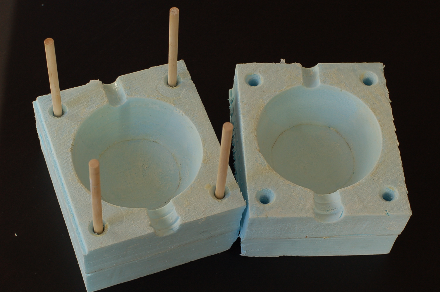
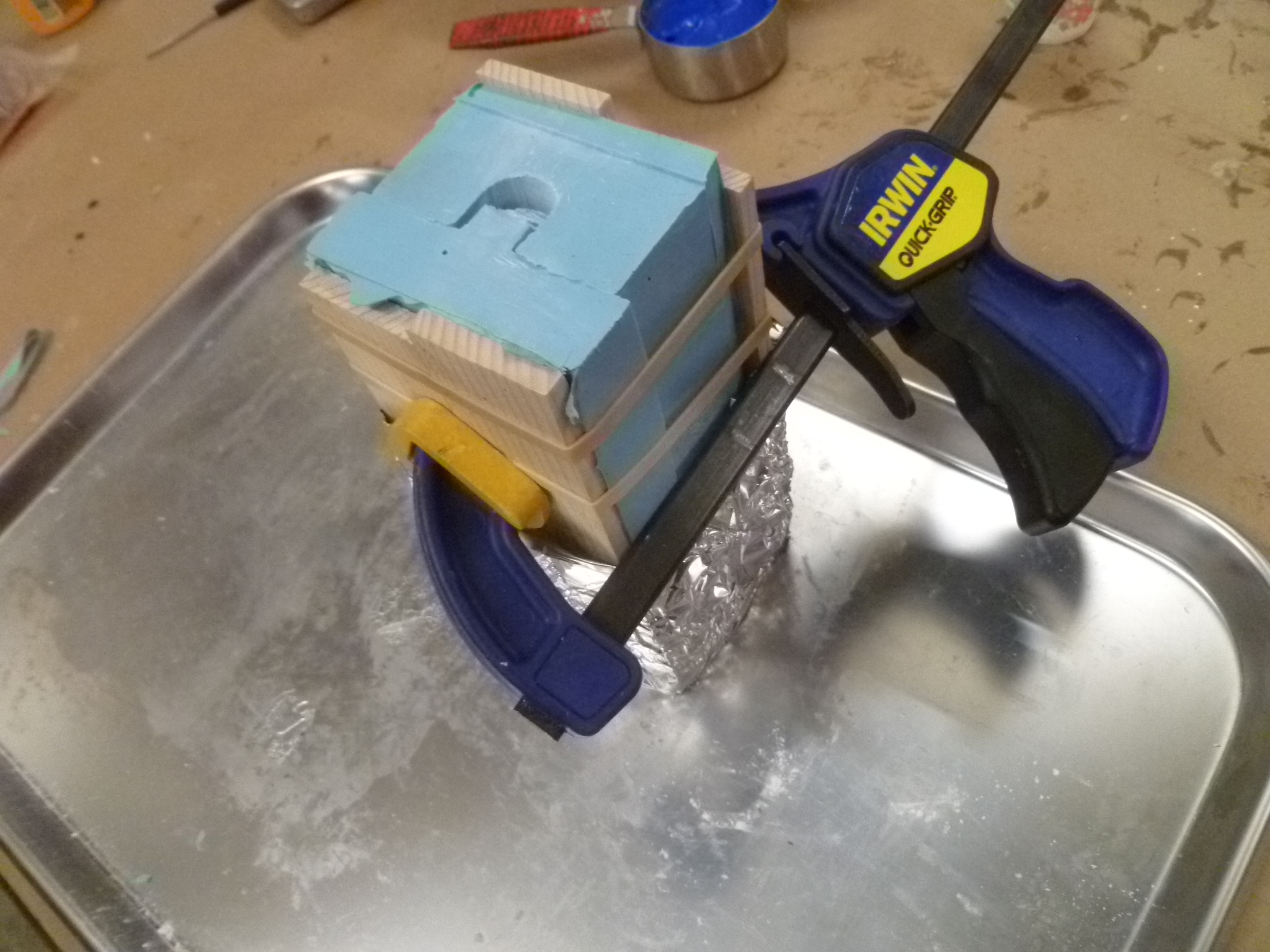
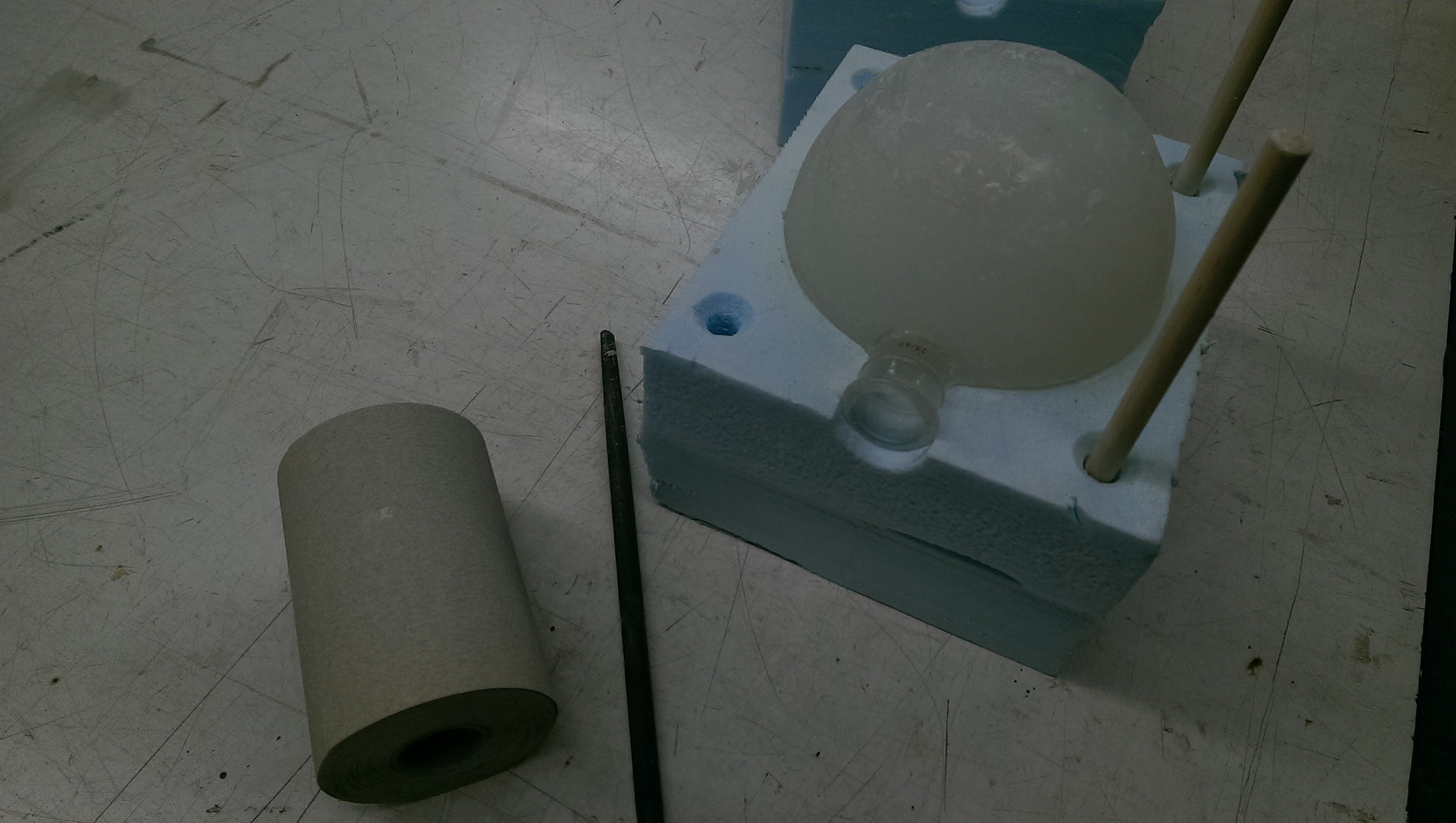
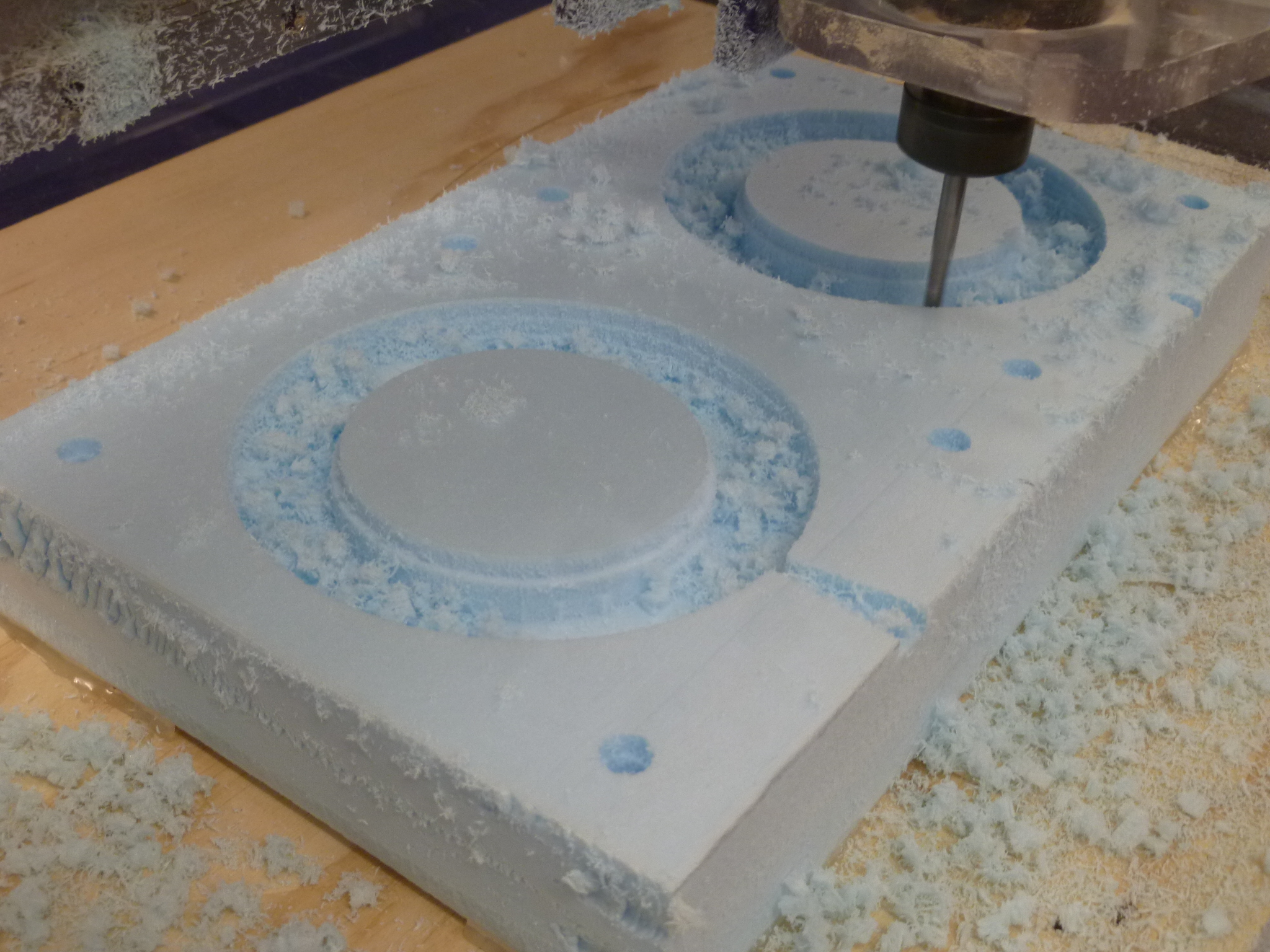
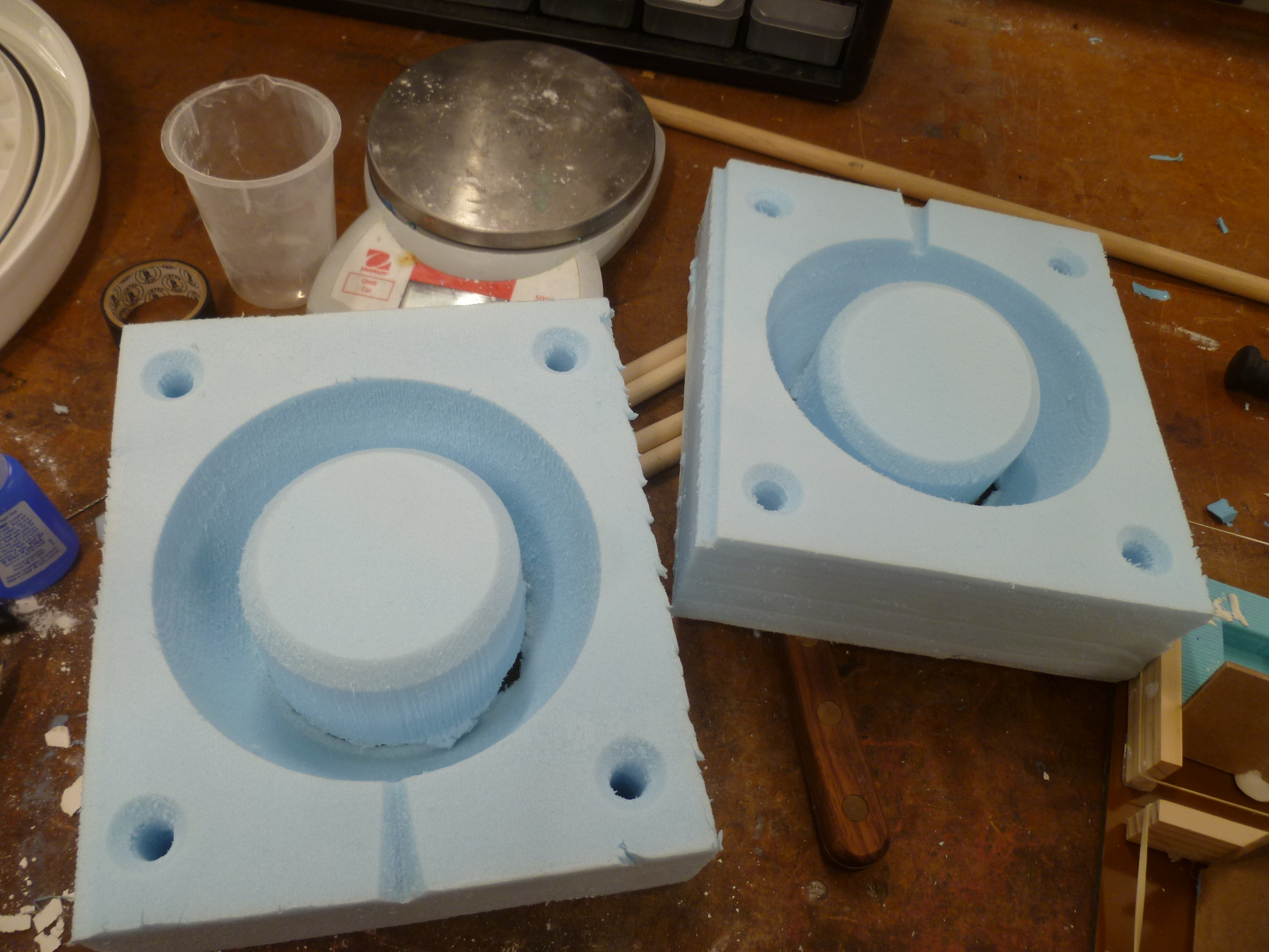
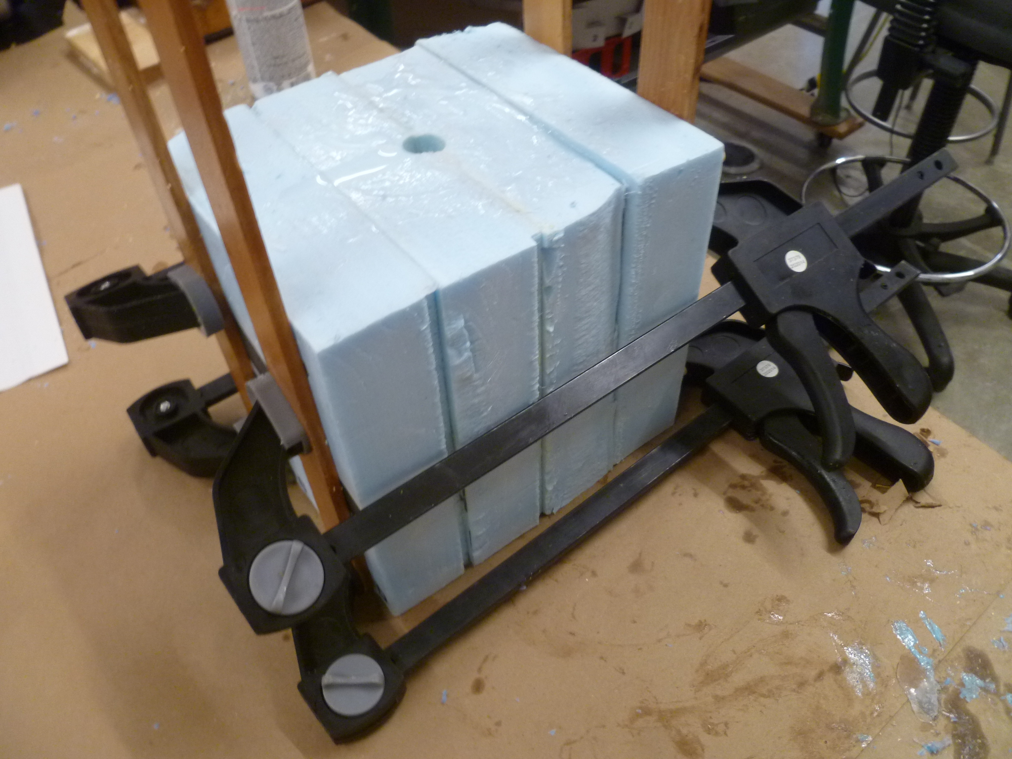
Which brings us to the mold itself. In order to mill out two halves of a 5.5" sphere, I needed two 2.75" deep hemispheres. Too big to easily mill out of wax. Foam it was! Since our foam was only 2" thick, I needed to glue two together (with Gorilla glue) to get the needed thickness. Our big ShopBot could mill down 4", but, of course, it was out of service. Our upstairs desktop ShopBot could handle 2" at a time. Fine.
I sliced the star into four layers, which I would glue together after milling. I added some holes, so I could slide some dowels through as registration pins.
Milling was relatively uneventful. In fact, having to cut only 2" slices at a time actually saved some time. I could just cut out a puck from the inner mold, which, if I were milling it all in one go, the endmills would have to have turned into dust.
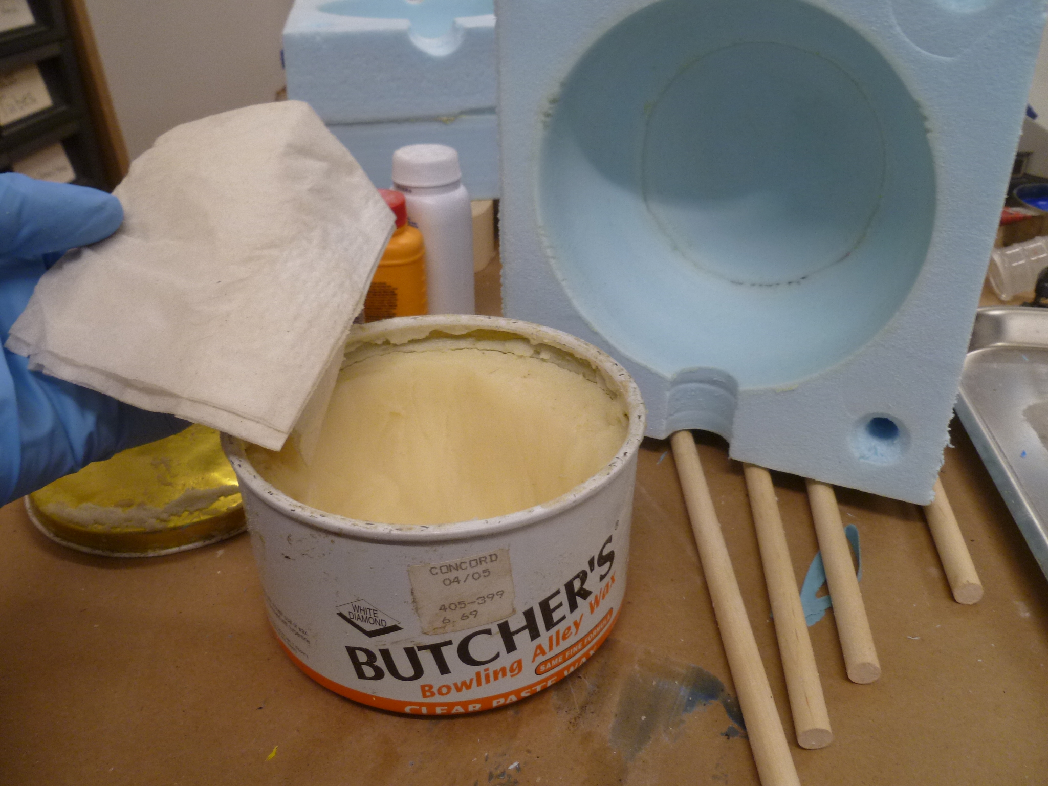
Next challenge was how to get silicone to release from a large-pored foam like the polystyrene we use. I was told at Reynolds that a simple acrylic wouldn't fill holes that size. I decided to use epoxy to fill the pores, and to use ample mold-release. In talking with Daniel, however, he recommended bowling alley wax, which we had in supply. The stuff is applied with a damp cloth. It smells like menthol and, well, bowling alley. I don't know that it ever hardened such that I could "polish" it, as the tin suggested, but a test smear with silicone on it released just fine. It would do the job.
I next needed to cut a hole in the mold to make room for the beaker's neck. I had originally designed a slot to hold my pedestal perfectly centered in the mold, but this became moot once the beaker entered the equation. To widen the hole, I was gonna use a drill bit, which would have torn the hell out of the foam. Daniel instead took me back into the Room of Requirements, where we found and sharpened some antique cork-cutting tool. It worked beautifully! Always use the right tool for the job.
I cut a second hole opposite the beaker neck, and set about actually casting the damn thing.
Mixing and pouring MoldStar for something that big was ... an ordeal. Admittedly, I should have done the math earlier. A 5.5" sphere has a volume of roughly 1500 ml! Thank god for my 500 ml beaker, I only had to mix and pour a full liter of MoldStar. I finished up one kit, and ended up using an entire additional kit. All that we had barely added up to a liter. I was worried.
But, with time running short, I had to work with what I had. I didn't have a big enough cup / bowl to mix it in (my fault: always prep!). 500 ml of A and B combined essentially filled my red Solo cups to the brim. Putting mixes in the vacuum chamber creates a frothy top layer for a little while, and I didn't have any goo to waste. I had to use every drop I mixed if I had any shot of filling the damn thing.
Because I knew it set relatively quickly (just a few minutes), I didn't want to mix the second half until the first half of goo was already poured. I poured the first mix into an open half of the mold, then inserted the beaker, then clamped it shut, then turned the mold upright, prayed the beaker plugged the hole (it did), and continued pouring through the hole I had cut on top of the mold.
I then mixed the second half in a hurry, worried the first half would set forming an ugly separation line between the layers (maybe wouldn't've been an issue). It was difficult to get a thin stream going while pouring from such a full cup, and I ended up with glops of silicone all over the top, plugging up the fill hole, and generally making a mess and not going anywhere I wanted it to. It congealed while I was still trying to pour, leaving me panciking and shoveling a mucelagenous mass into a gummed up fill hole.
After an ulcer-inducing wait while it set (about 30 minutes), I tried to open the mold. I had seen other people's molds end up stuck together by excess flashing, and waxed the non-sphere parts of my mold as a precaution. Fortunately, they worked, and the sphere came out without hesitation. However.
I didn't get it full. Fortunately, a good friend lives near Reynold's Molding and Casting, and picked up another MoldStar kit on her way to visit. I finished the pour, and am overall pleased with how it came out.
At the moment, I have the pieces configured for maximum ease of transport. The atoms are wired together, but separate from the AVR board. The battery case and AVR board are velcro'd to the bottom. Wires running under the board are held in place by twist ties hot-glued to the bottom.
The pedestal just sits in its hole, wires run up the back to where the star core sits atop it ...
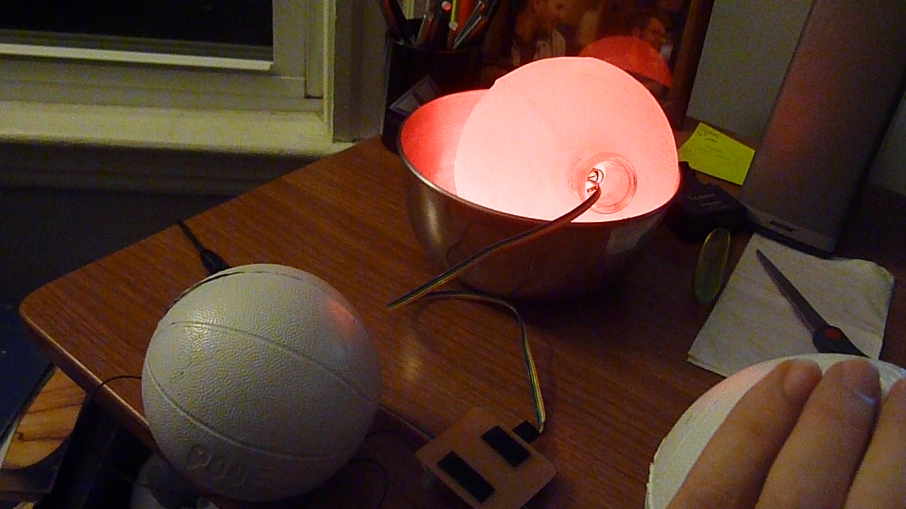
... which just barely fits through the neck and into the silicone star. While the step-response may be glitchy (see above embedded video), it glows beautifully.
There are some relatively small changes I'd make on the second iteration, but for a first stab at it, I'm pretty happy with how it came out overall. (Problems for Future Alex: debug and more precisely calibrate the code, chop the glass neck off that's sticking out of the bottom of the sphere, permanently attach the pedestal to the sphere and to the base, and maybe mill out a new base without the hole between the atom divots.) I have to admit, I was sometimes skeptical of the you'll-figure-it-out-just-ask-for-help pedagogy of this class, but I can now confidently say that I've learned quite a bit this semester.
I've learned that knowing how to make almost anything is very different from actually making it. It takes far more than just designing something on a computer and telling a machine to make it. There are an astounding number of constraints that stand between your vision and reality - equipment constraints, material constraints, sourcing constraints, timing constraints, physical constraints, mental constraints - which all must be factored into your design if things are to proceed smoothly. And even then, you'll miss a few things, and you'll find yourself having to think creatively within a multi-constrained context. And every tiny alteration you make to the design has unseen ramifications that ripple through the rest of the design process. It's thrilling and maddening, but if you can succesfully navigate it, you might just end up making a cool thing.
But these are not obstacles to making almost anything. Knowing how to navigate these constraints is an essential part of knowing how to make almost anything. And after this semester, I am much more aware of those constraints than when I began. I can't say with confidence that I could make almost anything tomorrow, but I'd at least know where to start.