SCROLL
finalProject 0000 0001 CAD 0010 cutting 0011 programmer 0100 3Dprinting 0101 elecDesign 0110 makeBig 0111 embedProg 1000 moldCast 1001 inputs 1010 outputs 1011 networks 1100 machine 1101 interface 1110 wildcard 1111 notes0100
3D Scanning and Printing
Group assignment:
Test the design rules for your 3D printer(s)
Individual assignment:
3D scan an object (and optionally print it)
Group Assignment
Characterise your lab's 3D printer(s)
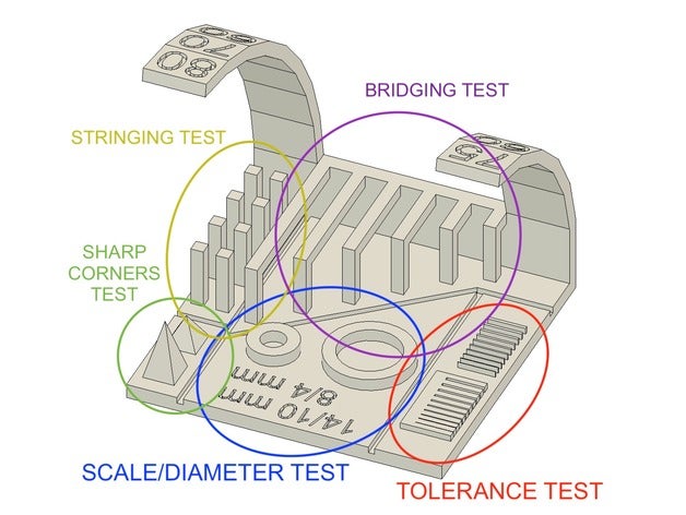
First we used a pre-made test file from Thingiverse. It tested bridging, stringing, scale/diameter, tolerance, overhangs and sharp corners.
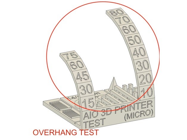

I was very impressed by the printier's ability to print overhangs up to 80 degrees from vertical when incrementing by 10 degrees every 5mm. That being said the print became a bit messy after the 40 degree section on the larger overhang and after the 45 degree section on the smaller.
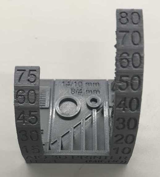


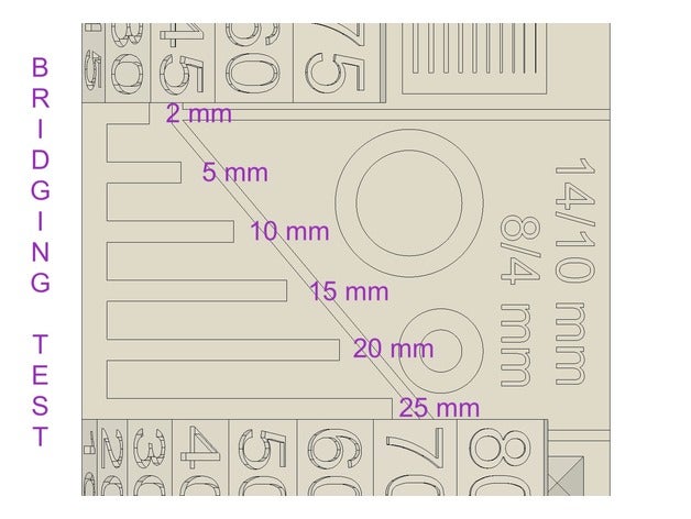
Horizontal bridging was successful all the way up to the 25mm bridge
The diameters of the circles were spot on.
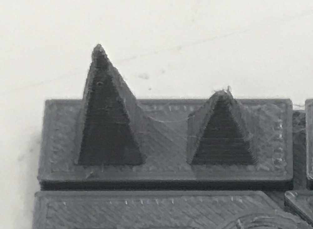
All of the towers were printed successfully with some light stringing, but nothing that couldn't easily be removed by hand.

The 4mm sharp corner test was frayed and messy at the top. The 7mm wasn't much better.
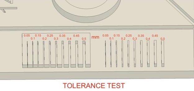
The tolerance test is where things didn't go as well.

The slots were printed pretty decently, save for the end bulging of the medians. The 0.1mm slot I'm not sure I would call successful and the 0.05mm slot was printed completely fused. It seems to me that with our Prusa MK3S it would be best to avoid going smaller than a 0.5mm slot
The protrusions didn't fair nearly as well. Only the 0.5 and 0.45mm blocks were printed. The printer didn't even attempt the smaller ones.
Neil's Test Files
Found under supports and unsupported here


![]()

![]()


Individual Assignments
Design and 3D print an object (small, few cm3, limited by printer time) that could not be made subtractively
3D scan an object (and optionally print it)
Design and 3D Print
Brainstorming an object to print
When thinking about what kind of object can be made by a 3D printer but not subtractively I came to the conclusion that an object inside another object would be the way to go.
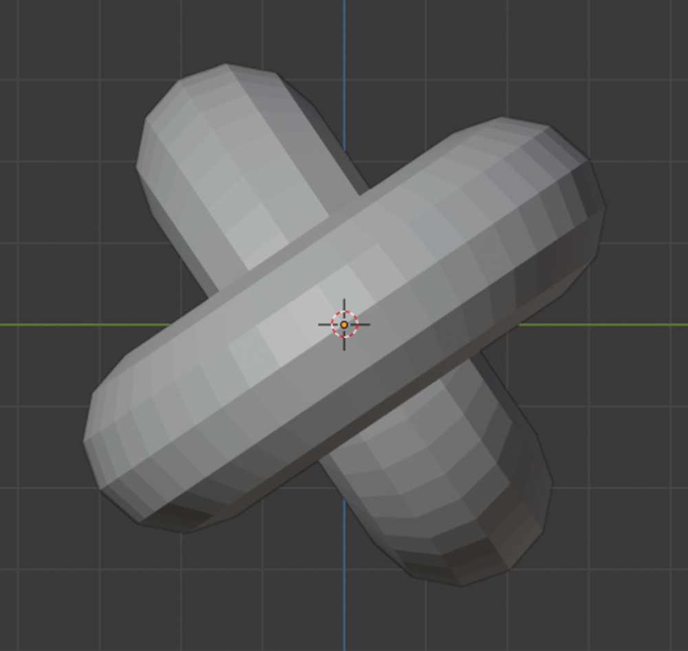
That being said, I did want to try out Blenders sculpting tools. I played with trying to sculpt a squirell head without a reference.

It was amusing at first but due to my unfortunate scultping ability It quickly became frustrating.
For my print design I'm considering chain links, ball and socket joints, hinges and objects inside cages.
During our section Jeremy Guillette (what a name) showed us an octopus with articulating tentacles. I am curious to see how it was made so I'm going to deconstuct it in Blender.

My 3D modelling skills (the lack there of) in tandem with time are going to be the limiting factors of this project. That being the case, tackling a relatively simple challenge will be most prudent... The chain it is.
Chain Modelling
First, I am going to change the units to mm and the scale to 0.001.
This Blender hotkeys reference will be useful.
Beginning with a torus, I am going into "see-through mode" using alt + Z and viewing along the X plane pressing B and dragging to select the right half of the torus.

I am pressing G to be able to move the selection and X to constrain movement to the X axis. I am dragging the right half out until happy with the shape.
Using alt + s I am able to adjust the thickness of the link. This is something I will need to tweak later when I add more links.
Pressing N I can view an objects dimensions


With one link drawn and correctly sized time to make more and inter-link them.
After trying to make this chain by hand for too long I am going in search of a more efficient way to do this.
This tutorial to the rescue!
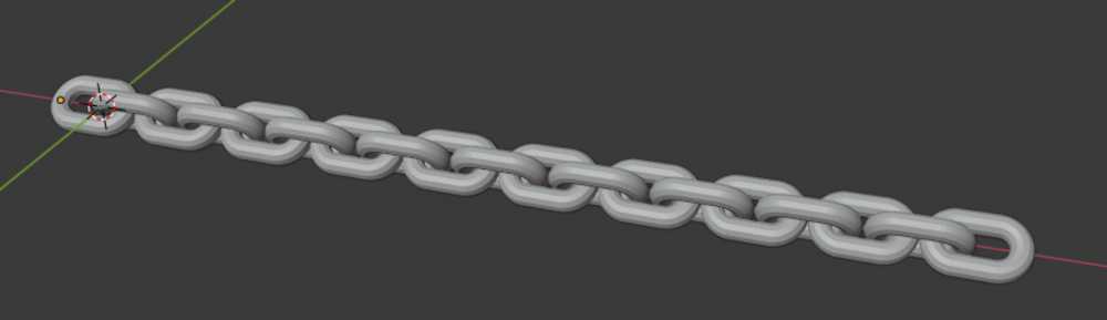
Following the above I was able to create this (array modifier will prove very useful):
The offset between links is determined by the distance of an "empty object" I created and the original link. This is described in the aforementioned tutorial.

Exporting the file as an STL (I will later test OBJ).
Downloading the Prusa Slicer and importing my STL file.

I am ticking the box for auto generated supports.


I am clicking slice now
Inserted an SD card into my Mac and am exporting Gcode to it.
Ejecting SD card from my Mac and inserting it into the Prusa MK3S
I'm selecting my file on the LCD display and away the printer goes.
Chain Printing
Went without an issue


Longer Chain Modelling
Since the three link chain came out satisfactorily, I am going to try to make a larger, cyclical chain.
Back to Blender to draw.
I'm going to use the same techniques as before except this time I'm going to set the array modifier by absolute length of the array rather than unit count. I'm also going to decrease the size of the links.
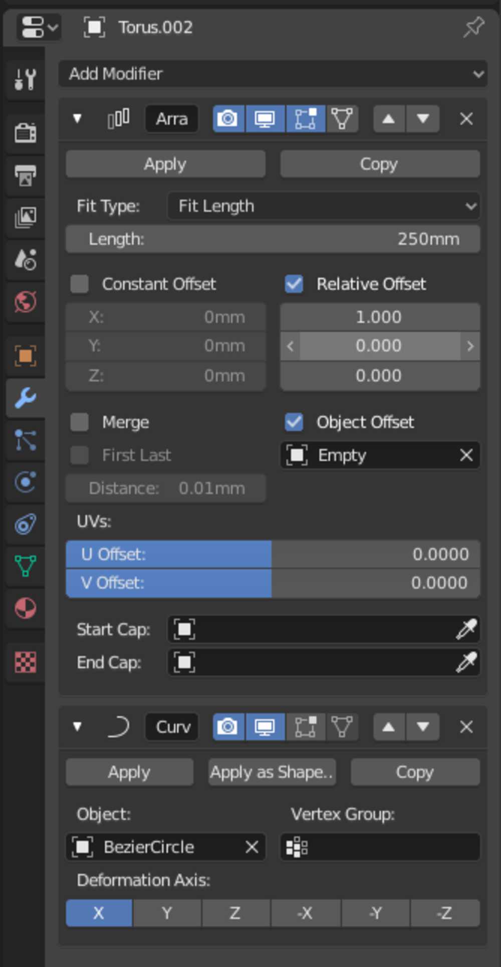
The rotational offset is based off of the relative rotation of the empty object I created to the first link.
I have two options for the rotation of the links:
I'm going with the 90 degree rotation for simplicity's sake.
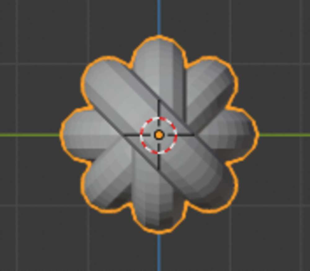
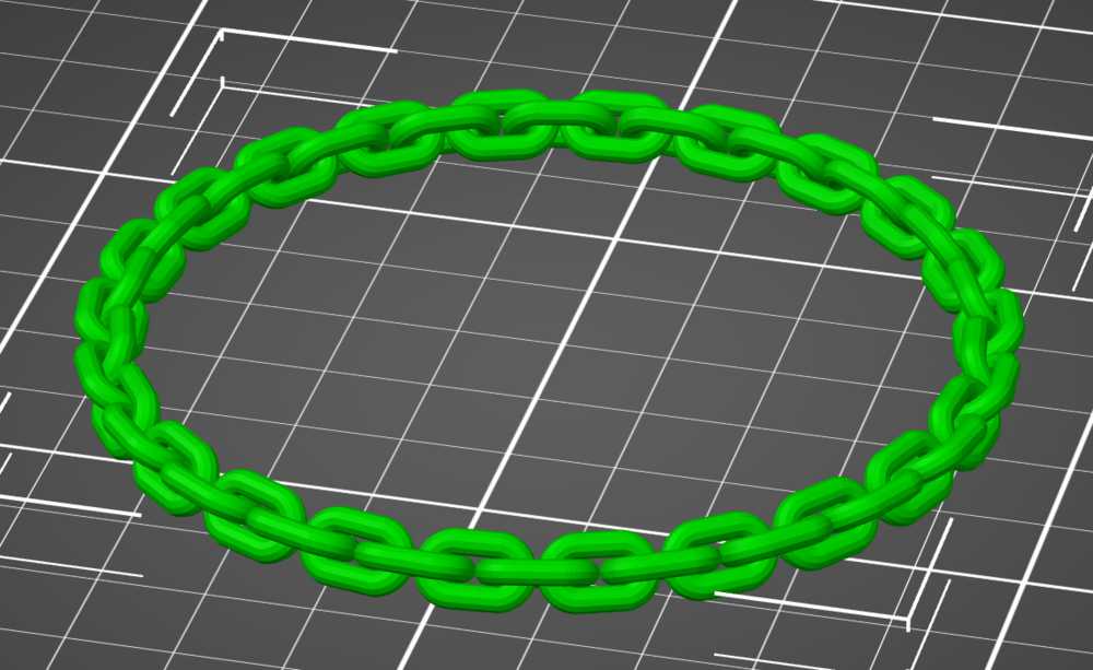
This is the scene:
![]()


I want the edges of the links to touch ever-so-slightly to provide a little extra support
Time to import into Prusa Slicer
Longer Chain Printing
Importing into the slicer
Adding support material
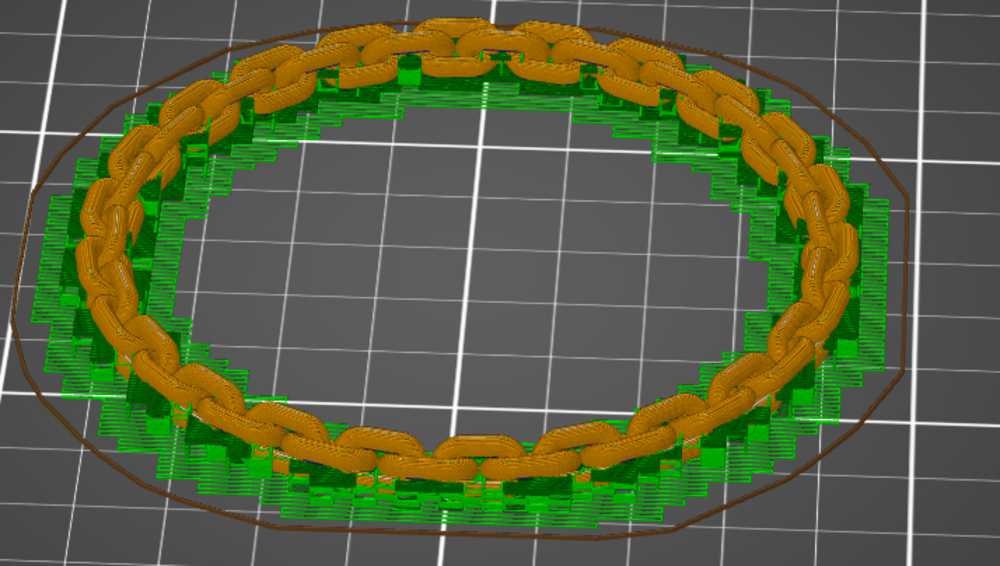
Clicking slice now
Exporting Gcode to SD card
Inserting SD into printer and commencing print.


After removing the support material, the whole thing was still pretty stiff. After a day of it living in my pocket it loosened up.
3D Scan
Jeremy Guillette was kind enough to bring his Artec Space Spider (~$25,000) to the Harvard Lab for us to use.
We are using a lazy Susan to turn our objects once we start scanning. This will allow us to smoothly scan all sides of our objects without having to move too much.
The lazy Susan is topped with an intricate print of flowers. This helps the scanner recognise and track the surface the object to be scanned is sitting on.
I placed my tub of corn starch on the lazy Susan for scanning.
Initially, the scanner was not picking up the blue lid of the tub. We were unsure as to the exact reason. One hypothesis is that the scanner has trouble recognising that shade of blue. I don't know why that would be, but it is the only thing I have seen the scanner be unable to pick up so far.
I added chalk powder to the lid in an attempt to give the scanner something non-blue to pick-up on.
Then I flicked the thumb switch on the Space Spider (love that name) up once to preview. Everything looked good.
Flicked switch up again to start scan. I pointed the scanner at the base of the object so that half the view was of the flower pattern and half of the object. This helps the scanner register the horizontal surface the object is on.
I then slowly turned the table, raising and lowering the scanner to cover the object top to bottom on each side.
Once I had covered all sides of the object and then some I flicked the scanner switch down once to stop it scanning.
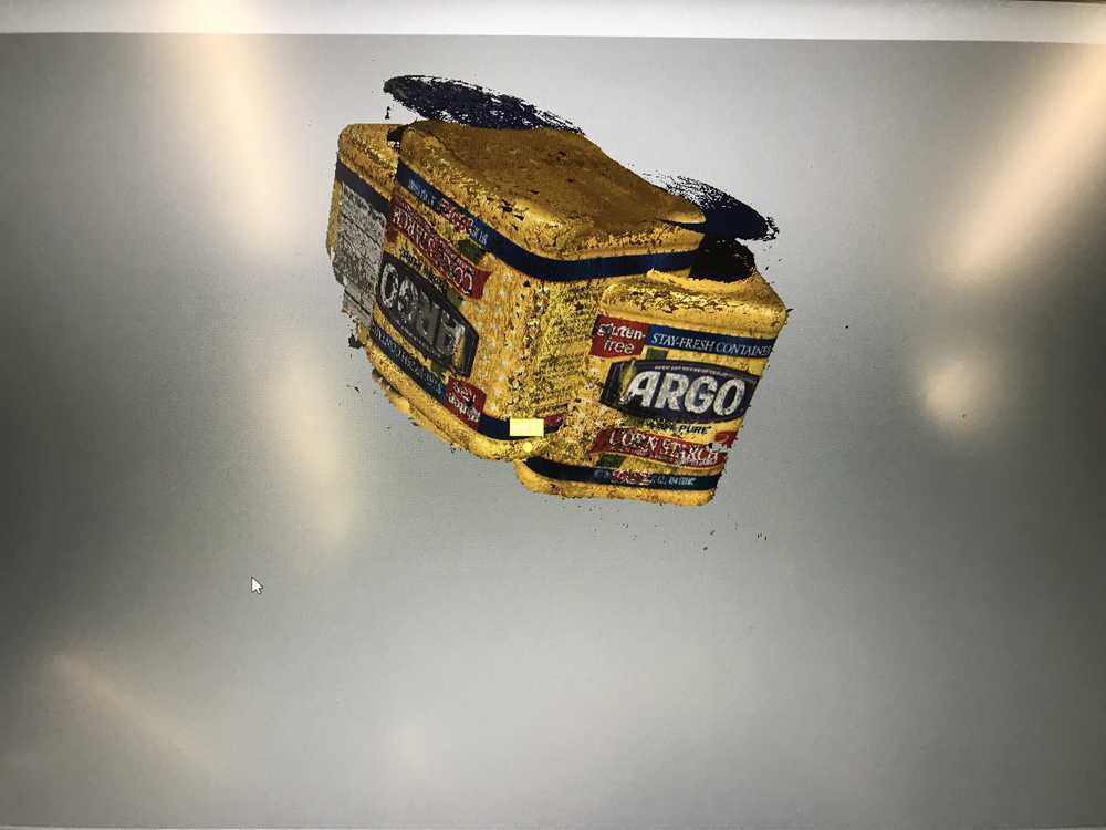
Below is what the display showed post scan. You can tell that the scanner could not pickup the sides of the lid (they were not coated with chalk)
Auto-align - this shape is simple so I was confident the software could align the data without my help.
Next initiate "Global Registration"
Outlier Removal - cleans up the scan noise. Messy pieces around the object disappear.
Sharp Fusion - - this converts the data from a point cloud to a more continuous geometry.
Lastly, 'Fill Holes' - this does what it sounds like. Will be interesting to see how it fills in the sides of the lid.
Pre-'fill holes':
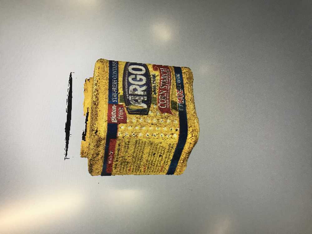
Post-'fill holes':
The algorithmic hole filling did a pretty good job. The lid is definitely misshapen, but for how much data was missing I can't complain.
Here is the final render
Further Notes
The STL file is 149 MB... How do I compress that for uploading here?
The Allston ceramic studio has a 3D printer for clay... I want to try it.