SCROLL
finalProject 0000 0001 CAD 0010 cutting 0011 programmer 0100 3Dprinting 0101 elecDesign 0110 makeBig 0111 embedProg 1000 moldCast 1001 inputs 1010 outputs 1011 networks 1100 machine 1101 interface 1110 wildcard 1111 notes0010
Computer Controlled Cutting
Group Assignment
- Characterise your lab's laser cutter.
Individual Assignment
- Create a cardboard, press-fit construction kit that can be constucted in multiple ways (extra credit if it includes a non-flat surface).
Group Assignment
Characterise your lab's laser cutter.
Speed and Power
I thought it best to make a matrix of squares in the thunder laser software where the power would decrease along the X axis and speed would increase along the Y axis.


Each colour of square is set to be cut at a different power and speed, depending on its position in the matrix (as shown below). Rob told us that when cutting carboard he finds that setting the power at 100% and speed at 50mm/s does the job satisfactorily.

Rob's ideal setting of 100% power and 50 mm/s speed does seem to be hitting a sweet spot between a good cut and a quick job (higher speed lowers chances of burning).
As the last two columns weren't cut through well, I am creating a second matrix that will more aptly test the bounds of the laser cutter. See below:

On this go round, I had to gently tear out the square that was cut from the 100% - 50 mm/s square. Hence, I believe that a setting of 100% power and 45mm/s speed would be ideal for cutting cardboard on this machine.
Focus
I created another series of rectangles to test the laser cuts at different focuses (heights of the laser mouth above the material). These are 5mm heigh and 4, 3, 2, 1 and 0.5mm wide, respectively.

Below is the cut with the laser at the manufactures suggestion of 6mm above the surface you are cutting. This is measured by dropping the laser head down to the plastic tool pictured below as it sits on the substrate.


I incrementally raised then lowered the laser head for each series of cuts.

The most obvious failing came at the 18mm height. The cuts were curved at the corners and burnt a larger surface area.
Cuts from heights of 6mm and lower seem very similar to me. It looks as if there may be some curving around corners at the low extreme.
Kerf
I created another series of squares: 15, 10, 5 and 2mm in width. The two smallest of the squares were sucked down into the the bed of the machine by the vacuum and were rendered unrecoverable. No matter, the larger two will do just fine.

The squares ended up being roughly 0.15mm thinner than designed. This would mean the laser is cutting about 0.075mm extra off each side. It is possible the laser is centered over the tool path, and has a diameter of 0.15mm, but I don't know if that is true. I should test the dimensions of the holes the cutter leaves in the cardboard.


I designed another shape to test the dimensions of the cuts left in the cardboard.


The cuts are also off by roughly 0.15mm. At this point it is reasonable for me to conclude that the laser is centered over the lines drawn on the computer and at 6mm high off the surface of the material, has a diameter of around 0.15mm.
Rate
I cannot figure out how to change the pulse rate of the Thunder laser in the lab and as I'm the only one here at this point, I don't want to mess up any settings for the next person who uses it.
Joint Clearance
I tested this in the interation process of my press-fit construction kit (documented below). The ideal joint width for me was 4mm wide with the cardboard being just under 5mm in thickness. For a different project 4mm may be 0.5mm too wide, but the construction of my design benefitted from the ease of joining pieces. Having less clearance would have exacerbated the construction issue of mishaping thorugh man-handling. While a 3mm wide slot can be fitted over the cardboard (the width of my original slot design), that width ended up forcing one side of the joint outwards- not ideal.
Individual Assignment
Create a cardboard, press-fit construction kit that can be constucted in multiple ways (extra credit if it includes a non-flat surface).
Goals:
- Make something both decorative and functional
- Use a living hinge
- Don't bite off more than I can chew!
Ideas
- Zepplin
- Tree shaped jewelry holder on a cylindrical base

I am going to make a tree because it fulfills more of the above goals.
The customisability will come from the leaves and other add-ons that can be attached to the main frame.
Pieces
- Two inter-locking pieces for the main body of the tree
- A long living hinge strip for the base. Similar to this cup holder:

- A circle to wrap the living hinge around and to put the tree on

Plan B: make a cuboid base
Dimensions:


Easier solution wins! I'm going with the circular clamp. Occam's Razor or something, right?
Drawing 1:
I am fairly unfamiliar with all of the software available to me, but I have used Adobe Illustrator a couple of times. I'm going to use that for the drawings. This is is a low-fidelity draft to test out sizing and fit.

Time to cut!
Cut 1
The dimensions I have the pieces scaled too were too large for the bed of the laser cutter - scaling down by 40%

Successes:
- The leaves work well - could consider chamfering corners of slot
Issues:


Drawing 2
- Increasing length of linving hinge to 378mm (was 377mm)
- Increased width of trunk slots to 4mm (was 3mm)
- Adjusted height of slots so that they meet exactly half way
- Made the trunk tabs 7mm long
- Chamfered leaf slot
Cut 2
Successes
- Trunk slots fit well
- Trunk tabs fit well
- Slightly chamfered leaves work better that the non-chamfered
Issues:
- Living hinge is still too short
Just realised I can stretch the living hinge enough to make it fit. This discovery solves too problems:
- The hinge now fits around the circle
- Due to this elastic property, I only need to anchor the ends around the cirlce. This is more elegant than the proposed clamp solution and takes far less time than the interlocking gear-like solution.

Drawing 3
Added tabs and slots for living hinge anchoring (as per above sketch).

Cut 3
Successes:
- the hinge anchor works (as long as there is both a base and top cirlce to anchor to)
- whole thing feels pretty solid
Issues:
- Top circle falls in pretty easily
- Tough to assemble without damaging the living hinge (left side of middle photo)
I might make the hinge a tad longer so I don't have to stretch it as far


Draw 4
- Making support struts (and neccessary slots) for base circles
- Making hinge longer

Cut 4
Hooray! It basically worked! There are a couple fine tunings to be done.


Issues:
- Slots are about 0.8mm too thin - this is something I was ignoring earlier, but with the finicky assembly involved in adding struts it is worth fixing
- Tabs on struts are about 0.5mm too long
- Branches could be redesign to better hold jewelry
- Only need the tree slots on the top circle - omit from bottom circle
- Maybe add a little bush at the bottom of the tree?
Draw 5
- Widened slots
- Shortened tabs
- Redesigned branches
- Added off-shoot branch
- Removed excess slots in base
- Added a little bush

Living-hinge design files from Obrary
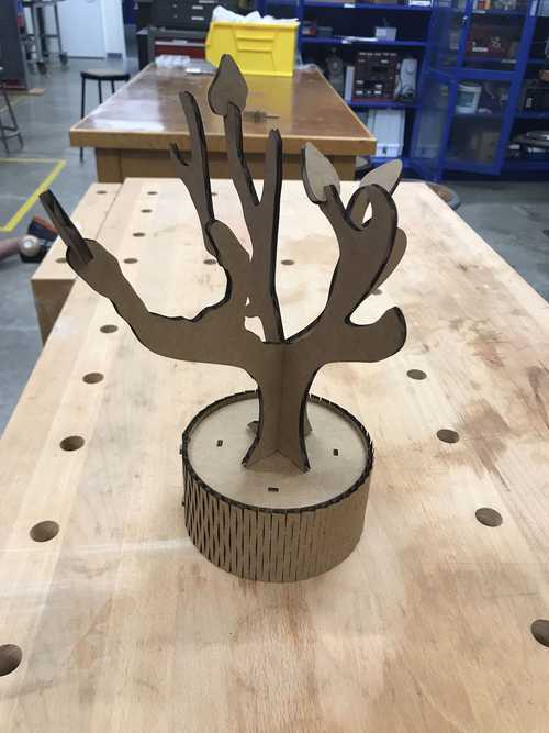
Cut 5
I think we have it folks!

Reflections
If I were to contiue working on this piece, which I might, I would:
- Add another secondary branch and branch slot to increase customisability
- Add a little squirrell or two - similar to the bush, but maybe in the tree
- Make the base a box for other jewelry
For future projects I would like to make a miniture photography studio with a roll of white paper as the back drop so I can keep the photos more consistent and cleaner
Vinyl Cutter
Assignment:
Make anything on the vinyl cutter
Goals:
- Make something for my friends
Idea
A sticker saying "The Foolishness"
When we had to pick our rooming groups freshman year each group was required to come up with an appelation for their group. My roommates and I called our group "The Foolishness"
The Process
Design
I used an online text-to-png converter to create a png file out of my chosen text and font
I wanted the sticker to be the negative of the letters so I added an outer rectangle from which I would take the letters out post cut.

Next, I uploaded the png to mods where I edited the size of the design and defined the tool parameters

I pressed 'send to printer' and waited for the job to be done

Transfer
I cut off a piece of sticky transfer paper and applied to the cut area
![]()
Next, I carefully peeled off the entire rectangle - letters included
![]()
Weeding
Weeding the letters out with a pair of sharp tweezers was very straight forward

Final Application
Stuck it into my notebook

Looks good to me. I might play around with different fonts before making more for my roommates
Reflections
Next I think I will try to make some iron on patches and maybe some t-shirt designs for the labs t-shirt press