SCROLL
finalProject 0000 0001 CAD 0010 cutting 0011 programmer 0100 3Dprinting 0101 elecDesign 0110 makeBig 0111 embedProg 1000 moldCast 1001 inputs 1010 outputs 1011 networks 1100 machine 1101 interface 1110 wildcard 1111 notes
Final Project
THIS PAGE IS A FOLLOW ON FROM 0001
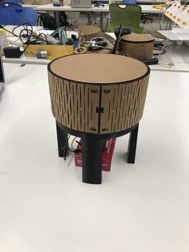
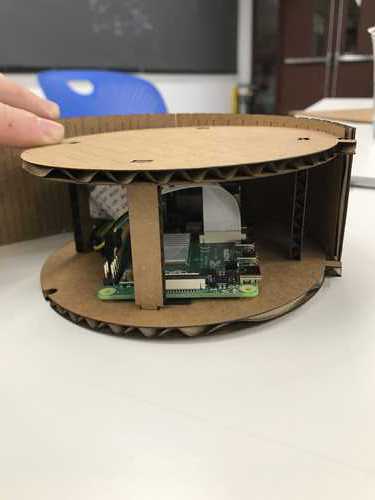
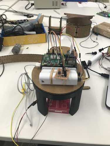
This is where the prototype ended up by the end of the class!
What is supposed to happen:
- When a face is detected by the camera, if the face is in the center of the frame, nothing happens. If the face is not in the center of the frame, the camera rotates to point at the face.
What currently happens:
When the face is in the center of the frame, nothing happens. When the face is not in the center of the frame the camera will rotate past the face and stop.
The issue:
- The face detection program runs rather slowly. It takes a moment for a face to be detected and the appropriate action to be taken. The motor moves too quickly passed the face for the face's new relative position to be registered and the appropriate action taken. I found it very difficult to get the camera to move slowly enough (with PWM), but with enough strength to carry the apparatus.
The solution:
- The next iteration will use some gearing down of the motor to make it move more slowly. This will also allow the motor to maintain its strength.
- I could also look into running this on a more powerful computer that would analyze the video frames at a faster rate.
THIS PAGE IS A FOLLOW ON FROM 0001
This project is a compilation of mini-projects from past weeks' work:
- FOR THE DRUM DESIGN SEE 0010
- FOR ELECTRONICS SEE 0101
- FOR FACE DETECTION SEE 1101
- FOR WIRELESS DEPLOYMENT & VIDEO STREAMING SEE 1011 and 1110
Advancements of the above mini-projects that make up this project are documented below.
Idea Genesis
When my five younger siblings and I were growing up, my parents would sometimes bring us to museums. We hated it. There was nothing duller or more exhausting than following our parents aimlessly around the sterile, life-sucking labyrinths of old paintings. Inevitably, our feet would start to hurt. We would all keep our eyes peeled for benches or chairs to sit in and complain from. However, chairs were always hard to come by in these sparsely furnished chambers. If we did find one, chances are it was occupied by a museum staff member, but sometimes, the good lord would smile upon us and we would enter a new room and there would sit a thriving oasis in this dreary desert of artifacts— an empty chair.
We were not rescued yet. In fact, the real battle had just begun. There were six of us and only one chair. They say blood is thicker than water— chairs are thicker than both. The race to the respite would commence. Soon, a winner would be crowned with an unfurrowed brow and anointed with spiteful words from his siblings.
For my final project I would like to give these children an oasis in the dreary desert of artefacts, but one that is so much more nourishing than a simple chair. I want to give them a trick, a riddle, something that will snap them out of their lifeless daze and spark curiosity and a laugh. I want to give them a chair they, despite appearances, will be unable to sit in.
Project Proposal
This chair will present itself to the room as a willing aid in warding off the plight of weary feet. The chair will sense the location of said weary person as they approach. Once this unfortunate soul comes within a predetermined distance from the chair, the back of the chair will swiftly swivel around to face the approacher. If the approacher attempts to move to the new “front†of the chair, the back of the chair will swivel to follow her, making it altogether impossible to sit in this chair by ordinary means.
An extension of this project could be a second or even third chair, each with a pressure sensor in the seat. If two of these chairs are in a room both unoccupied, one may be sat in with no issue. However, once one chair is occupied, the second’s anti-seat function will be employed and it will forever abuse the weary until the first chair is evacuated.
I would imagine this turning into an unexpected, but welcome riddle the occupants of the room would be interesting in solving.
Implementation
Sensor
Goals
- Sense when a person, not any old object, comes within a predefined distance from the chair
- This project is all about impeding the realisation of an intention. Ideally the chair would only turn when a human intends to sit. Obviously I can't read the mind of the the nearby person (yet). I will need a proxy for intention. I think the direction of the person's face, a proxy for their gaze, could act in turn as a proxy for their intention to sit. I would like to be able to sense when someone is facing the chair.
- When multiple people are near the chair it should default to acting against the closest person.
Options
First I will try to make the motor spin via bluetooth commands.
- If implementing a computer vision system ends up being too advanced for me, I could have a photodiode that would deactivate the chair in the dark (for safety reasons)
Ultra Sonic Sonar Distance sensor
Issues
- Won't detect direction
- Won't detect face
Computer Vision and Facial Recognition
Would need two or three cameras, depending on the field of view of each, to have a 360 degree view around the chair
Could detect proximity by the size of the face . Bigger face = closer person. (Thanks Harnek!)
In the case of the back facing camera, the motor turning the chair could be programmed to work to centre the face in the camera's field of view. (Thanks Harnek!)
For faces towards the front of the chair, the motor could be programmed to work to get the faces off screen left or right (depending on the side) until the back camera could see the offending face and the motor could then work to center it in that field of view. (Thanks Harnek!)
Lazy - Suzan bearing
I would like to 3D print the bearing allowing the back of the chair to turn with the motor. Inspired by Joon's 3D printing project, I think I could do this completely in-place rather than with marbles as shown at the following places:
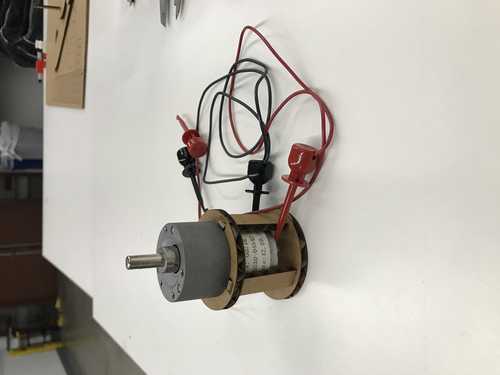
Motor
It seems that I can either use a simple geared motor or a servo motor.
Because I will be getting constant feedback on the chair's position relative to the approaching person from the cameras, a simple geared motor and some kind of "while not in position, turn" loop should do the trick.
Art Stuff:
Politics of my Final Project
My final project is intended to function as a game to spark some excitement in weary gallery or museum guests, namely children dragged along by their parents. The intentions, statement and critique driving the proposed installation run to the extent of the previous sentence. That being said, it is impossible to create an object devoid of the connotations, implications and historical significance of the constituting materials, technologies and related ideas. For that reason, I think it is important to consider the following points in the context of this project:
Initial racism of facial recognition technologies
- There were quite a few issues with facial recognition technologies not recognising faces with darker skin tones. This was due to a lack of testing on darker skin tones before releasing the technologies to the public.
Issues around surveillance, especially that which utilises facial recognition.
The politics of dening a seat or position to a person. Who is being denied and who is doing the denying?
Software and Electronics
For the software and electronics of this project see: 1101 and 1110
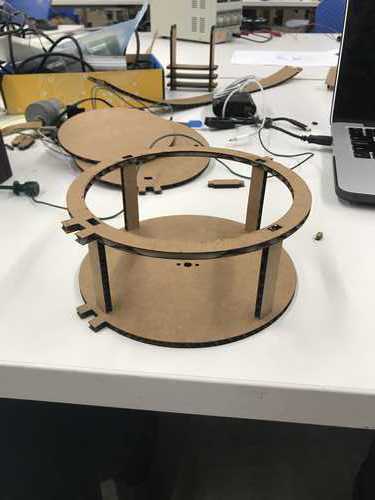
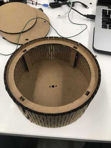
Structure Design
Inspired by Neil's advice to follow a "spiral development" strategy. I will start by designing a very basic prototype that works completely and then create increasingly complex, but complete systems from there.
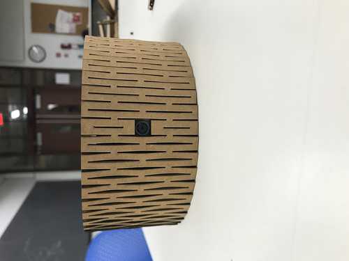
I am using the form I made in week 0001 as a jumping-off point. The drum-base of the jewelry holder is great shape for the seat of my chair. The circular design means it will look normal in any orientation, i.e. you wouldn't be able to tell something was up with the chair even if it ends up facing a different direction than it started.
First drawing:
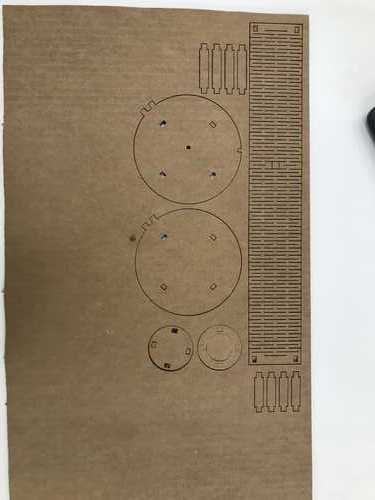
Issues:
- Hole for motor shaft too wide
- Need more room between supports in drum
- The ring for holding the motor need a wider inside diameter
- Tabs are too long- stick out past the cardboard they slot into
Second drawing:
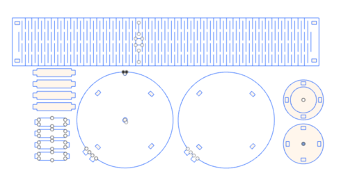
The electronics and interface work!
The motor keeps over correcting, passing my face and then overcorrecting in the other direction:
Issues:
- Hole for motor shaft could be tighter.
- The camera is the only thing that NEEDS to be moved by the motor, however the camera is wired to the Raspberry Pi and the RaspberryPi is wired to everything else so EVERYTHING (except the motor and wall socket powering the pi) needs to turn with the camera. This means there are wires between stationary elements of the system and rotating elements of the system and THAT means TANGLES and snags!
- MOTOR TURNS TOO QUICKLY - the face detection program runs rather slowly, consequentially I need the motor to also work very slowly.
Solutions:
It would be great to get a wireless camera, but that is not feasible to do before the deadline, so I will still have to move the entire Pi. What I can do is find a portable power supply for the Pi. This power supply could then go inside the drum with everything else.
The bigger issue is the wires to the motor. I could find a way to at least manage the tangling wires, but that is not a completely solution.
- I could devise a rotational bearing connection to fit under the motor-- like two circular rails that connect to the legs of the motor. The wires could then always be in contact with the rails, but free to move along them.
- I could keep the power supply stationary with the motor, and connect it via a switch that can be toggled wirelessly. That certainly would be the more elegant option.
I could try to add some PWM to my C code.
- I could also manually reduce the voltage flowing through the battery.
PWM
Added PWM to my C program:
xxxxxxxxxx// Pin to 0// Pin to 1// Check if input pin receiving high signal// Check if output pin not sending high signal// Time on// Time off int main(void) { // Enable change of prescale register and set prescale to divide by 1 (makes timer run at 8MHz) CLKPR = (1 << CLKPCE); CLKPR = (0 << CLKPS3) | (0 << CLKPS2) | (0 << CLKPS1) | (0 << CLKPS0); // Clear PA2 and PA3 output signals then set as output pins clear(PORTA, A2); set(DDRA, A2); clear(PORTA, A3); set(DDRA, A3); while(1) { // PB0 turns on PA2 // PB1 turns on PA3 // While PB0 is receiving AND PA3 is off while (receiving(PINB, B0) && off(PORTA, A3)) { // PA2 on with PWM set(PORTA, A2); on_delay(); clear(PORTA, A2); off_delay(); } // PA2 off clear(PORTA, A2); // While PB1 is receiving AND PA2 is off while (receiving(PINB, B1) && off(PORTA, A2)) { // PA3 on with PWM set(PORTA, A3); on_delay(); clear(PORTA, A3); off_delay(); } // PA3 off clear(PORTA, A3); }}
Center Window
Need to widen the area in which a face is considered to be centered. The motor keeps over correcting so that it just goes back and forth never lingering in the middle long enough to register my face.
I'll increase the window from +/- 30 to +/-50.
xxxxxxxxxx # While face to camera's left if int(round(x + w/2)) > midline + 50: # Fill in cv2.rectangle(frame, (x, y), (x+w, y+h), (255, 0, 0), -1) if ENVIRONMENT != 'dev': # Turn right turn pin off and left turn pin on GPIO.output(24, False) GPIO.output(23, True) logging.debug('left') # While face to camera's right elif int(round(x + w/2)) < midline - 50: # Fill in cv2.rectangle(frame, (x, y), (x+w, y+h), (255, 0, 0), -1) if ENVIRONMENT != 'dev': # Turn left turn pin off and right turn pin on GPIO.output(23, False) GPIO.output(24, True) logging.debug('right') else: logging.debug('center') # Turn off both pins if ENVIRONMENT != 'dev': GPIO.output(23, False) GPIO.output(24, False)
Was testing this code when everything suddenly stopped working... :(
Debugging
Potential fails:
- Something on motor board fried
- Pi GPIO pins not working
I will use a couple LEDs and a bread board to test the GPIO pins
If they work, and I hope they do, I think I will remake the motor board.
If they don't work, I will switch to different RPi GPIO pins.
The LEDs light up, hence the RPi's GPIO pins must be working.
This means that something is awry with my motor board. Chances are my H-bridge was fried earlier when I was testing with the multimeter. I remember bridging two ISP headers and hearing a little beep.
I'll replace the H-bridge, test the whole setup again and if it doesn't work then I'll also replace the micro controller.
I was advised that a 9V battery is not the ideal power source for my motor as it is designed for high voltage low amperage systems. A better choice would be 4 AAA batteries. I'll switch that out.
New 4 AAA battery power supply and motor driver... no dice. The voltage out of the power supply is 4.4V... not sure that is enough juice to run the motor.
- Tested on a table top power supply with as low as .4 V and the motor worked, so not a voltage issue
I tried reprogramming the same micro-controller to see if it was fried and it successfully programed so nothing wrong with that component.
- Wrote a very simple C program to see what the motor driver is doing with a voltmeter.
xxxxxxxxxxint main(void) { // Enable change of prescale register and set prescale to divide by 1 (makes timer run at 8MHz) CLKPR = (1 << CLKPCE); CLKPR = (0 << CLKPS3) | (0 << CLKPS2) | (0 << CLKPS1) | (0 << CLKPS0); // Clear PA2 and PA3 output signals then set as output pins //clear(PORTA, A2); //set(DDRA, A2); clear(PORTA, A3); set(DDRA, A3); //clear(PORTA, A3); set(PORTA, A3); return 0; }
For some reason the H-bridge is outputting out both OUT pins, even though it is only receiving on one IN pin... odd.
After testing many different connections and replacing the H-bridge several times without uncovering anything suspicious, I'm going make a whole new board as a final stand.
I'm also going to use a motor with a larger gear ratio (1:131) as I need the camera rotation to be very slow.
In case of system failure on the day, I figured out how to set up my system with a pre-made motor driver board. It works very well:
Issues and Solutions:
H-bridges are finicky! They must be installed carefully! If an H-bridge is acting up (say outputting on two pins, when it is only getting in put on one IN. pin), REPLACE it!
- H-bridges also need at least 8V running through them for the motor power. Make sure that you have that with a voltmeter.
POWER SUPPLY - this turned out to be one of the biggest issues I faced - but I didn't realize until very late in the game.
Structure
Using fusion to draw up some 3d models:
A toothed cap for the motor shaft:

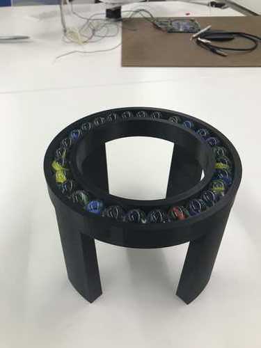
And a base that will hold marbles in a track, acting as a lazy suzan bearing:

Back to circuitry
This is the current circuit. I'm finding that the H-bridges need to be very carefully installed.
The bottom pad should be lightly covered in solder. I have been putting down solder and then using copper braid to remove the excess. Same for the pad on board.

After hours of pulling my hair out because the motor failed to turn, I think I have narrowed my woes down to two root causes.
Messy installation of H-Bridge
- Covered above
Inadequate power supply
- I tried everything from a single AAA battery to three lithium batteries in series, nothing worked. It seems that none of the conventional options could supply enough current to my motor. I did finally find a solution:
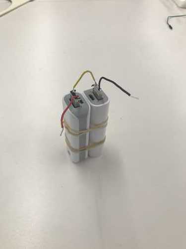
This is two 5V / 1A in series. It was my salvation.
Here is the project so far:
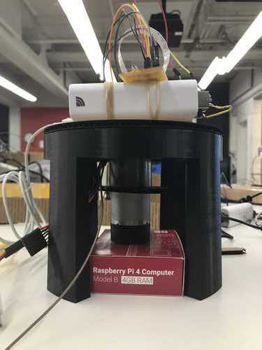
It's messy, too big and lacking a support for the motor. Still much to do.
Now that my power supply problems are sorted out, I'm going to retry PWM to slow my motor as much as possible. I'll use an off delay of 16 micro seconds.
Update: I fried 4 mobile chargers - still unsure why this happened. Maybe I shorted something. Maybe the motor was drawing more current than even the battery packs could provide.
I'm also going to widen the "center window" to +/- 250.
While the +/- 250 ranged worked fine on my Mac, the PiCam does not have as wide of a field of view, I'm going to have to stick with +/- 80 and rely on really slowing the motor down.
In this first test you can see how the motor over corrects each time it sees that my face is not in the center.
I slowed the motor down using PWM, but now it is not strong enough to move the top apparatus.
Annnnd now the batteries are dead.
While I wait for them to charge I'll work on a better housing for the electronics.
And something for the motor shaft to give it some grip (the other geometry from before wasn't great out of the 3D printer).


Assembled