Week 01
Computer-Controlled Cutting
Laser Cutting
For the laser cutting assignment I designed a kit of parts for making reconfigurable baskets. The idea is that from this set of parts you could change their arrangements based on your needs over time. I used Fusion 360 for the design,
creating variables for material thickness, the width of the parts, the outer diameter of the basket and the spacing between horizontal elements. From the one model an infinite number of basket shapes and sizes could be selected. I identified
three spacings and three outer diameters that seemed useful. This 3x3 grid of parameters creates nine possible baskets.
 Basket options in Fusion 360.
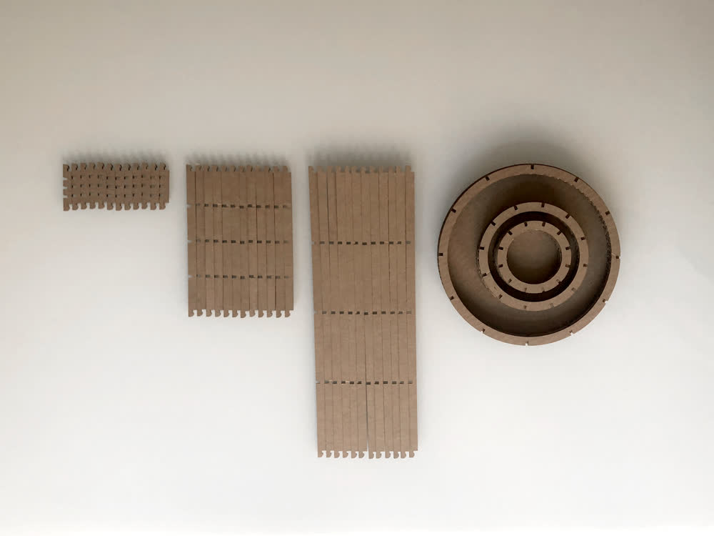 All of the parts.
The vertical ribs and horizontal disks of the baskets all notch together as a friction fit, but an important design feature is that the notching at the top and bottom of the ribs is inverted. This means that the disks in
the middle of the basket all push inwards on the vertical ribs while the disk on the top and the plate on the bottom push outwards. This essentially locks the basket together. It also means you have to rely on the flexibility of the cardboard
to be able to assemble and disassemble the baskets. This would not work with a material that doesn't have some give. Order of operations of assembly is also key. First the middle disks are attached to the vertical ribs before the top disk and
bottom plate lock it all together.
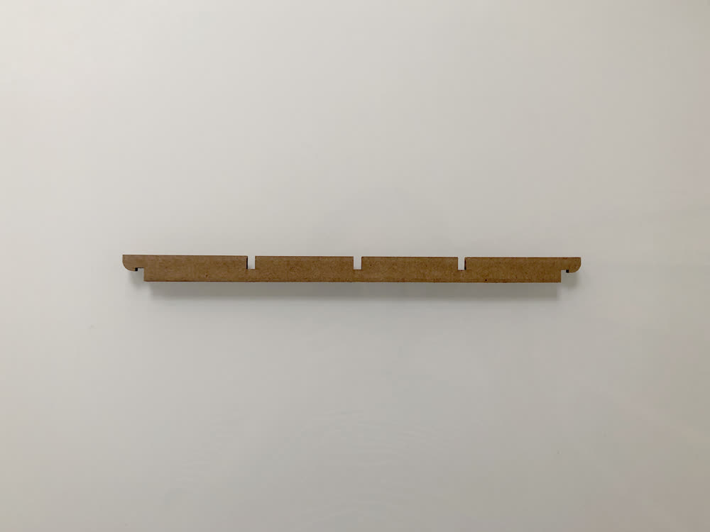 Vertical rib showing inverted notches at top and bottom.
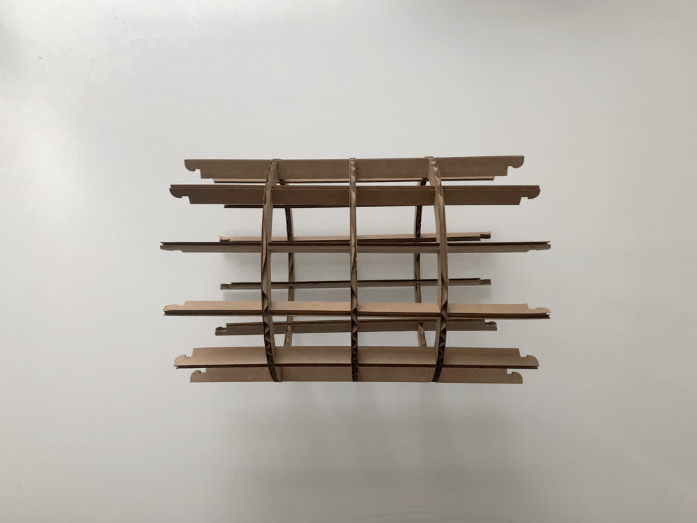 Step one of assembly.
 Basket options IRL.
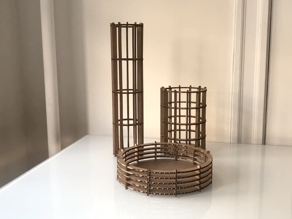 A family of baskets.
Overall this worked fairly well. The geometry of the notches at the top and bottom could use some iterating but they worked just fine using cardboard. If this were going to be developed into a product the durability of the cardboard would
become an issue pretty quickly. I could imagine a material like corrugated plastic being effective.
Vinyl Cutting
I decided I would try to make a window decal that would serve as both a solar clock and compass. Stonehenge in a sticker. The idea is that at a certain time on a specific day, the sun would project the geometry of a window decal onto a
surface to reveal a new geometry that points north.
First I plugged my latitude and longitude into the sun panel in Rhino. Along with a desired date and time this will give you the azimuth and elevation of the sun, which I modeled in Rhino as vectors. The azimuth is the angle from north
(y-axis) and the elevation is the angle from the xy plane. We get direct light in the morning in our kitchen so I started with 8:00 AM on Tuesday, September 15. Next I used my iPhone to get the orientation and elevation of our window.
Getting location data and inputting into Rhino sun.
I roughly modeled this in Rhino along with a table just below the window. Next I designed a simple geometry that points north. I extruded this geometry in the direction of the sun vector and took the intersection with the window plane
creating the decal geometry! I included two perpendicular lines in the decal to help position it on the window. This was removed once everything was in place.
 Rhino setup showing table, window, sun vectors, decal geometry and projection.
Rhino render plan view of table with projections at 8:00 AM and 9:30 AM.
Rhino setup showing table, window, sun vectors, decal geometry and projection.
Rhino render plan view of table with projections at 8:00 AM and 9:30 AM.
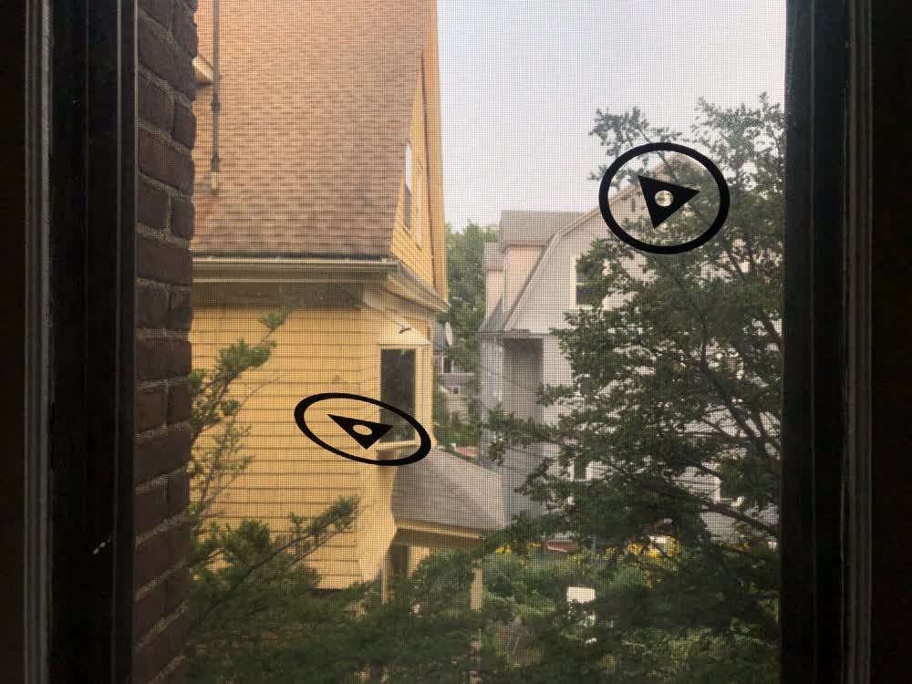 Decals in place.
8:00 AM rolled around and it turns out I made a bit of a misstep and our table does not get direct sunlight at that hour this time of year 🤦🏻♂️. By 9:30 AM, however, there was direct sunlight. The results were...not great. There are a lot
of variables at
play that could be leading to the
discrepency shown, but I'm not totally sure what is at the root of the matter. Likely the build up of several inaccuracies.
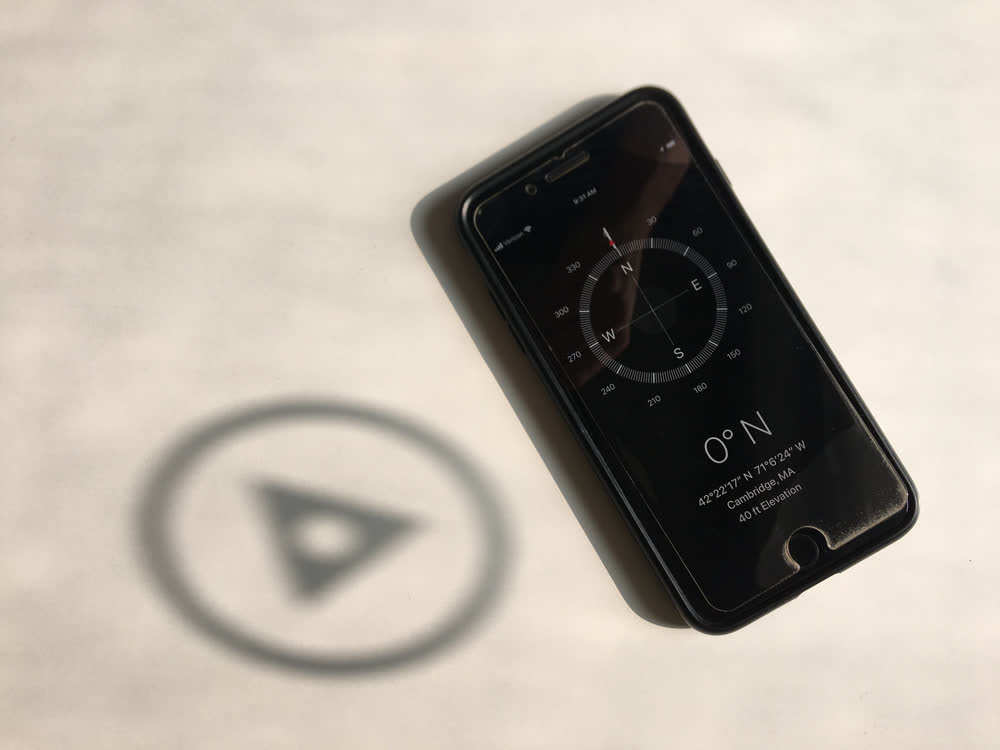 Decal projection at 9:30 AM.
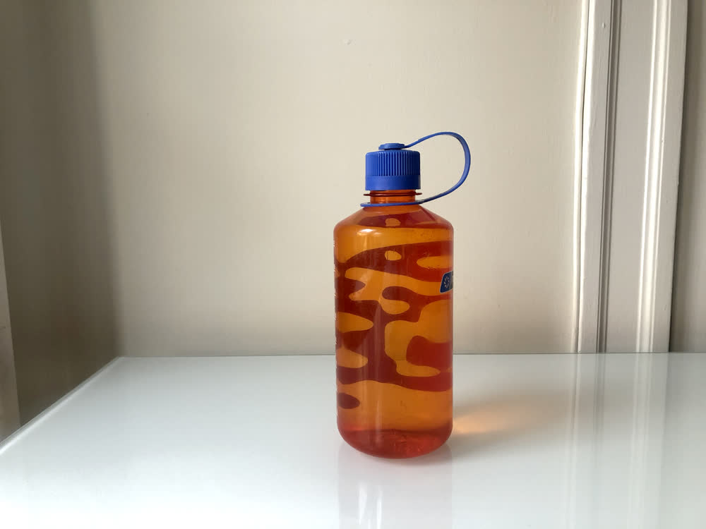
In addition to the solar clock, I used the vinyl cutter to turn my water bottle into a static lava lamp. I took an image of Perlin Noise and processed it in Photoshop to make a two-tone image. I took a little creative license around the edges
to make a self contained shape and then used Photoshop's create shape function in the libraries panel to vectorize this image. This step was only necessary because the image I started with was very small and I wanted to be able to scale the
graphic.
From Perlin Noise to blob.
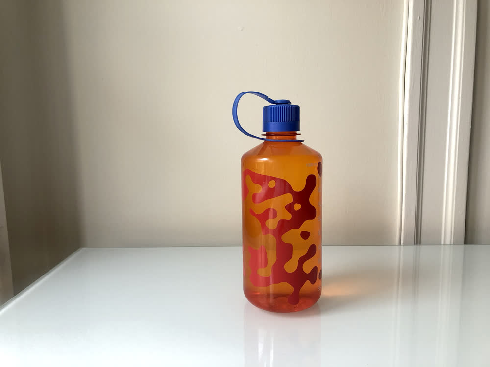 Lava lamp water bottle front and back.
 Lava lamp water bottle front and back.
I have used the laser cutter a fair amount for model making but the vinyl cutter is new to me and a lot of fun. I would love to try making circuits with copper tape when the time comes and I look forward to thinking about other applications
for it.
Files: 200913_basket_kit.f3d