With the bed flattened it was time to characterize the cutting quality of the machine. I did this using a file that tests the internal and external cutting of the machine. The gcode was generated in mods.
The first toolpath engraves the surface using a 1/64" end mill and the second toolpath cuts the part out of the stock using a 1/32" end mill.
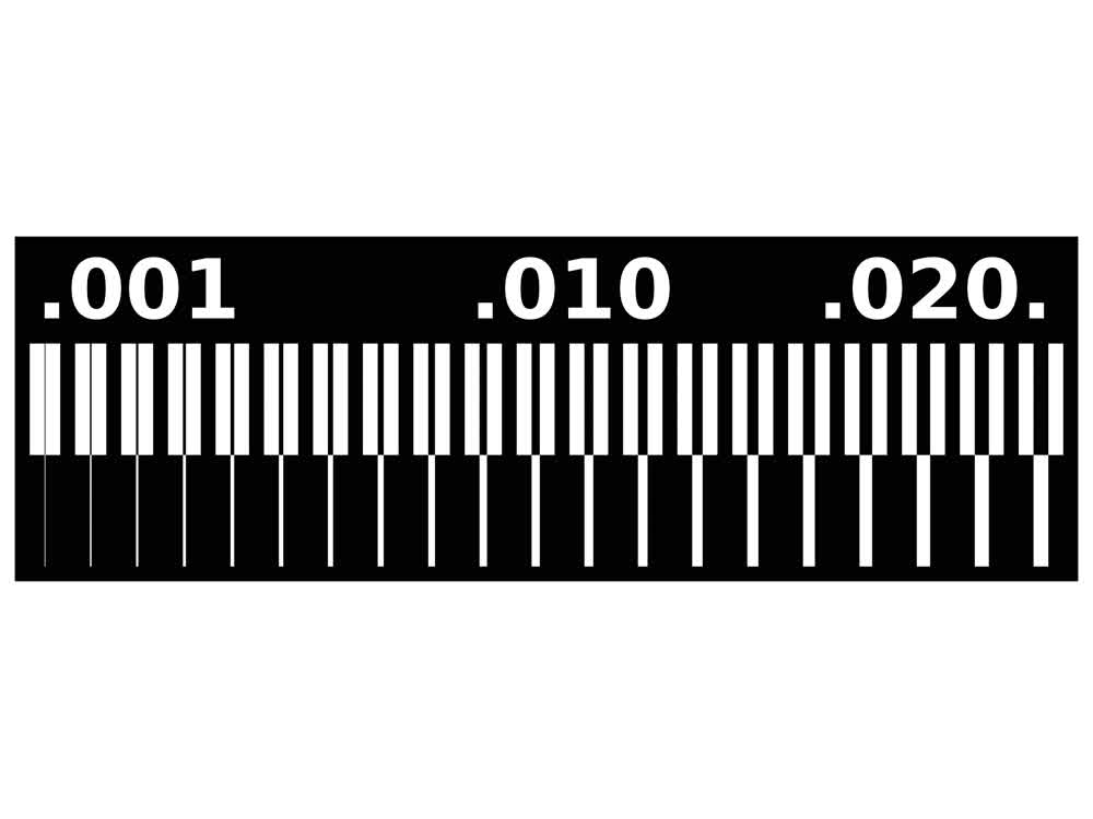 Design used to test machine.
The first time I ran this file, the stock was not flat on the bed because it didn't quite fit in the pocket that was made when flattening the bed. As a result, you can see that on one half of the job the bit didn't break through the
copper whereas on the other side it did.
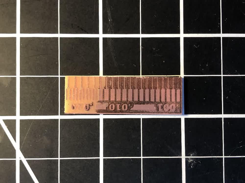 The result of unlevel stock.
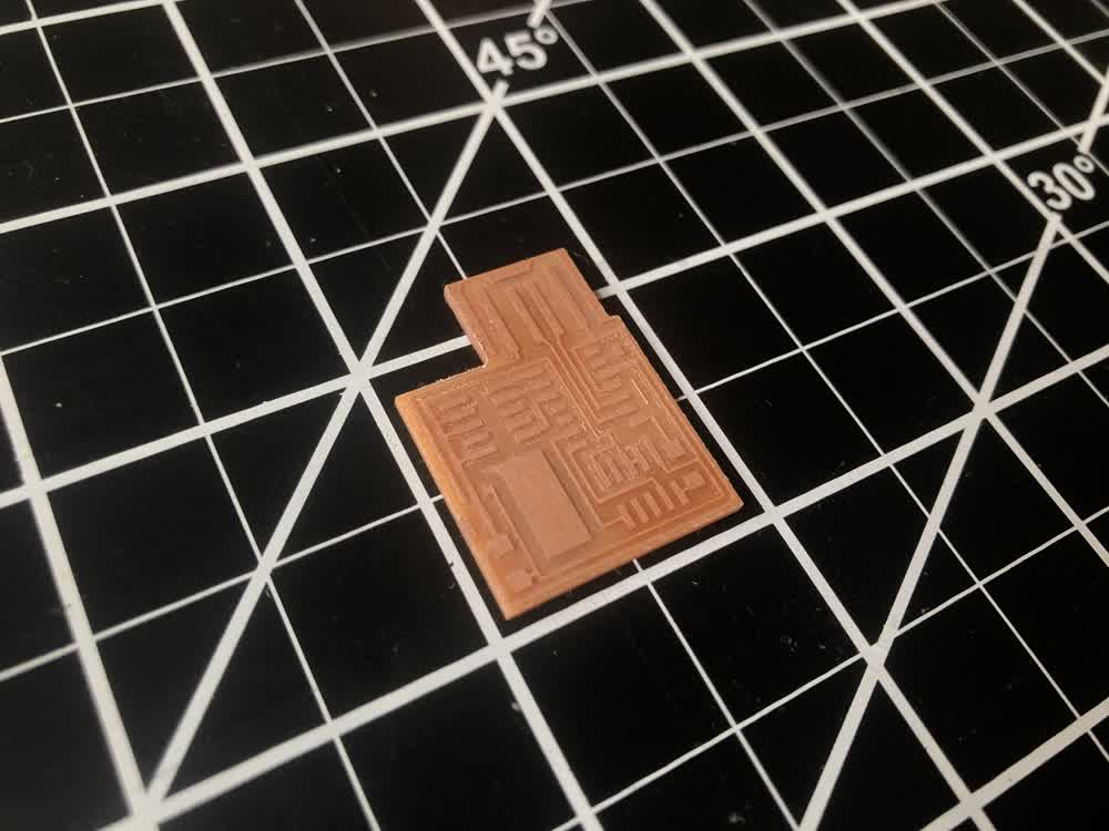
On the next try I had more success, but as you can see the cutting is quite fuzzy and the traces on the smaller end of the spectrum did not hold up very well.
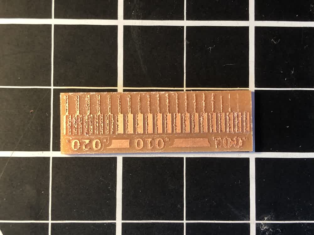 Fuzzy milling.
In one of the tutorial videos, Jake mentions that he was having success using a v-groove engraving bit as an alternative to the 1/64" end mills. I gave this a shot and the results were quite clean.
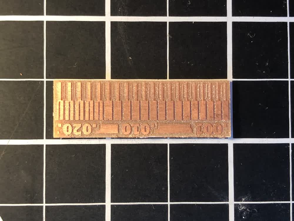 Clean milling.
Power Supply Cover
This week I also designed a cover for the power supply where the 110v is exposed. An .stl file for this is linked at the bottom of the page. It's a bit bulky but it clips onto the existing prints and power supply without any hardware
or the need to disassemble anything.
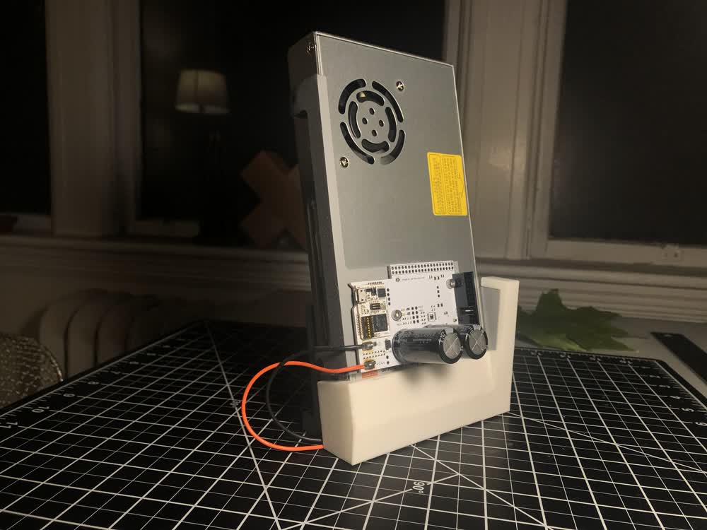 Power supply cover.
Milling and Stuffing PCBs
With the machine calibrated,it was time to take a crack at milling PCBs. The assignment this week was to make an in-circuit programmer. There are two categories of boards we could make: one for programming AVR microcontrollers and one
for programming
ARM microcontrollers. To be honest, I'm still wrapping my head around the differences between these options but this week I was mostly focused on fabrication. Hopefully the higher level understanding of the electronics will come in
the
next few weeks. In the end, I made one of each with the ARM board ultimately serving as a testing ground for figuring out soldering.
With the significant caveat that we are not yet designing our own boards, here is the basic workflow for making the programmers:
- Start with existing PNG of design.
- Use mods to generate g-code for engraving and cutout toolpaths.
- Run g-code on Clank.
- Stuff board with components.
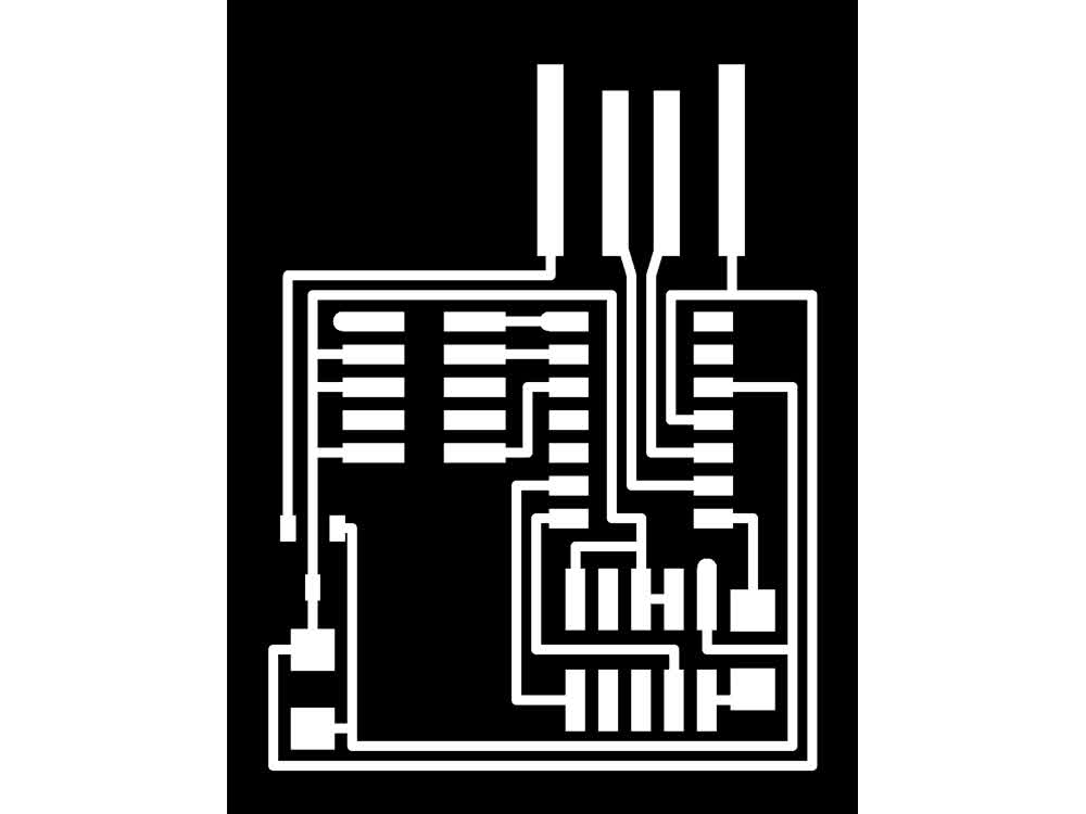 Design for ARM board.
 Milled ARM board.
 Stuffed ARM board. Oof.
Soldering was definitely a challenge. I've soldered in the past but mostly for making sculptures. The surface mounted components are quite small and my usual techniques were not going to cut it. I abused the first board I tried to
solder pretty badly mostly by overusing the heat gun but figured out a process that works for me along the way.
What I find works well is to start by putting a dab of solder on all of the pads for the component I want to attach. Then I take the heat gun in one hand and melt the solder as I place the component with the other. To attach the
microprocessor or microcontroller I first get some solder on all of the traces and then wick away the excess leaving really just a film of solder on the traces. Then again I take the heat gun in one hand and melt the solder as I place
the component with the other. From what I understand the process described above is essentially reflow soldering just without the solder paste.
Once I had this process worked out I stuffed the AVR programming board with FTDI chip and had much better results.
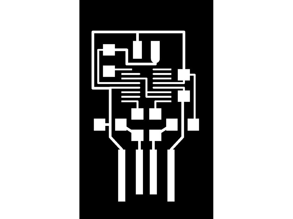 Design for AVR programming board.
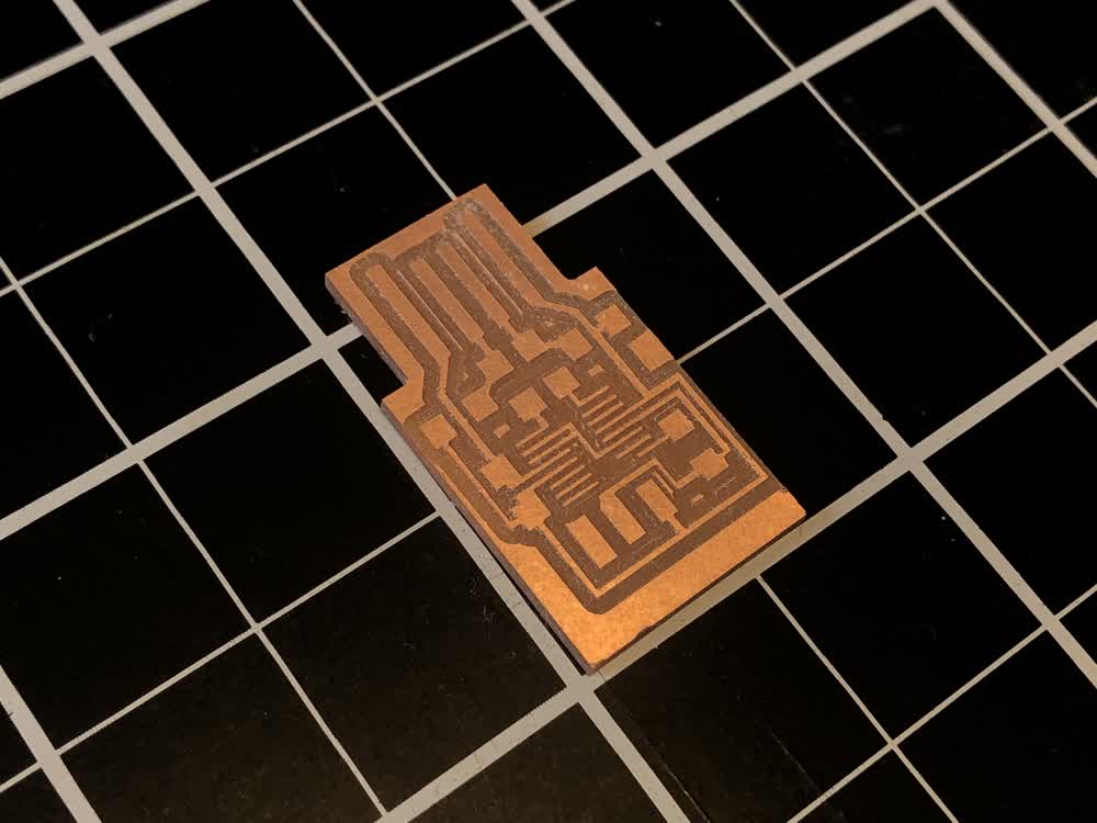 Milled AVR programming board.
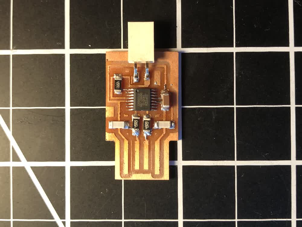 Stuffed AVR programming board.
File: 201009_power_supply_cover.stl.3dm