Week 11
Interface and Application Programming
Making a Trinket
This week I made a SAMD21 board based off of Jake's design found here. This board is essentially an Adafruit Trinket M0. I used two-sided PCB
stock and made the back a ground plane, making the routing much simpler. One issue I had was that the footprints I had for both the micro-USB and the SAMD21 didn't have enough clearance between pads for a 1/64" end mill. I did a
significant amount of editing in Rhino to rectify this, which is probably not the best solution, but it works. PNGs for this design at the bottom of the page.
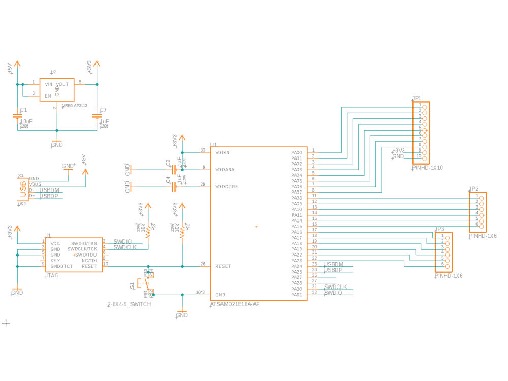 Modified Trinket schematic.
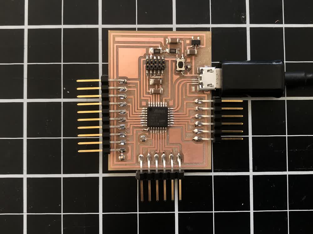
 Board design.
Making the board was fairly straightforward though soldering the micro-USB was a bit tricky. I used solder paste, which made this more straightforward. The reason for the micro-USB is that the orientation of the USBDM and USBDP pins on the
SAMD21 match the orientation of the corresponding pads on micro-USB, which is flipped on standard USB. I learned from Jake that USB is a medium-fast protocol so the physical design can really effect their functioning. It's best not to have
sharp corners or vias.
 Board design.
I have been using edbg
and an ATMEL-ICE in the architecture shop to flash bootloaders to my boards, but seeing as we no longer have access to campus, I had to try something different. I used the MAXDAP provided to flash bootloaders to clank along with pyOCD.
Instructions for how to do this can be found here. This is more less the same process as using edbg.
I used the Adafruit Trinket M0 bootloader. One thing to note about this is that though my design breaks out most of the free pins on the SAMD21, the Adafruit core only has pin mappings for 6 of these pins, because that is all that they make
available on the Trinkets that they sell. You can find the mappings here..It is possible to access the other pins through port manipulation, but I haven't gotten that far yet. Once the
bootloader was succesfully flashed, I just had to install the Adafruit core in the Adafruit IDE and was up and running.
OpenFrameworks
I decided to use OpenFrameworks to program my interface this week. OpenFrameworks is an opensource set of tools written in C++ that is geared towards creative coding. OpenFrameworks is similar to Processing in its goals and functionality.
Whereas Processing is written in the Processing IDE, OpenFrameworks can be written in any IDE. OpenFrameworks also allows you to publish on smartphones or as a native application. I mostly chose OpenFrameworks this week because I like the
workflow, rather than for performance reasons. I wrote my code in Xcode.
Communicating between OpenFrameworks and a piece of hardware can be done in a number of ways but I chose to use serial communcation. This video from Dan Buzzo really lays out how to
get it done. Essentially, you create an ofSerial object, which allows you to read and write to a serial port. If you are configured to the same serial port as the hardware, you're good to go! The code for this along with the code for my
interface can be found here.
Over the weekend I had been looking at Joseph Choma's book, Morphing, which deals with distorting and morphing between
geometries using parametric functions. I implemented some of these ideas in
OpenFrameworks, morphing between a spiraling sphere and a torus. I did this looking ahead to my final project, which is about basket making. It might be a stretch but I was imagining that you could have an interface in OpenFrameworks where
you can write functions to manipulate the design of a basket and then make it from that same interface.
On the hardware side, I made a simple circuit using a Force Sensitive Resistor that I hooked up to the board. The embedded program simply reads a value from the pin that the FSR is hooked up to and writes that value to the serial port:
int sensorPin = A2;
int sensorValue;

void setup()
{
  Serial.begin(9600);
}

void loop()
{
  sensorValue = analogRead(sensorPin);
  char inByte = 0;
  if (Serial.available() > 0) {
       Serial.write(sensorValue);
}
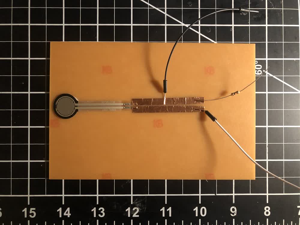 Force sensing circuit.
Back in OpenFrameworks, I read this value from the serial port and use it to change a variable that controls the morphing of the shape.
Interfacing!
A closer look at the interface.
I was surprised how straightforward and seamless it was to communicate between OpenFrameworks and hardware and will definitely be using this for my final project.
File: 201208_traces.png
File: 2012089_vias.png
File: 201208_outline.png