Week 09
Output Devices
Stepper Motor Driver
My final project is based around driving stepper motors, so I thought it would make sense to get my feet wet doing just that this week. The motor I'm using this week is a bipolar stepper motor with voltage rating of 12V and a current rating
of 0.4A. This means, I will need supply at least 12V to get the motor moving. I don't have a 12V power supply but luckily the benchtop power supplies in the architecture shops will work for this.
I based my design off of Neil's bipolar stepper driver that uses two A4953 boards to do PWM to drive a motor. Instead of the tiny44 in Neil's
board, I'm using a SAMD11D microcontroller. After using an AVR chip last week, I'm glad to be back using the ARM family. In prior weeks I had been using the SAMD11C but needed the extra digital pins provided by the SAMD11D. These chips
are pretty similar though so making the switch was straightforward. The other
notable difference between my board and Neil's is that I'm powering the MCU from USB power, rather than the same power used for powering the motor. This is because after flashing a bootloader onto the SAMD11D I was using USB to program it
through the Arduino IDE.
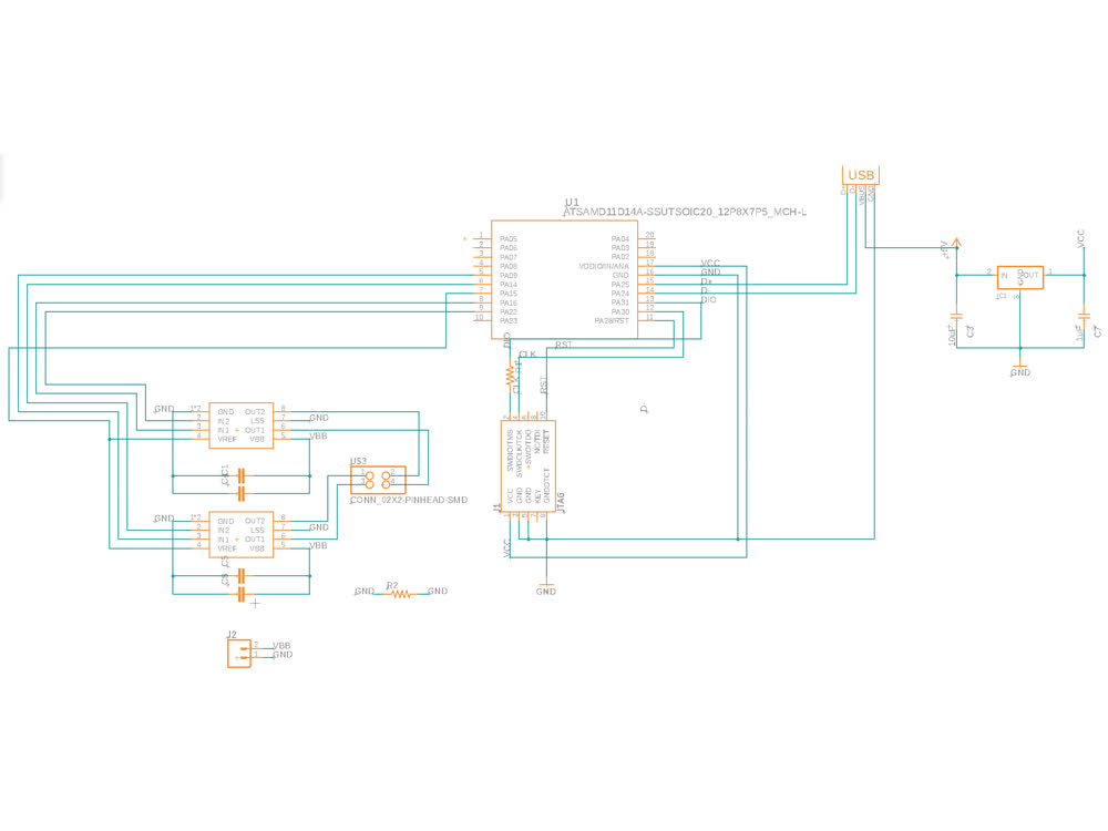 Stepper driver schematic.
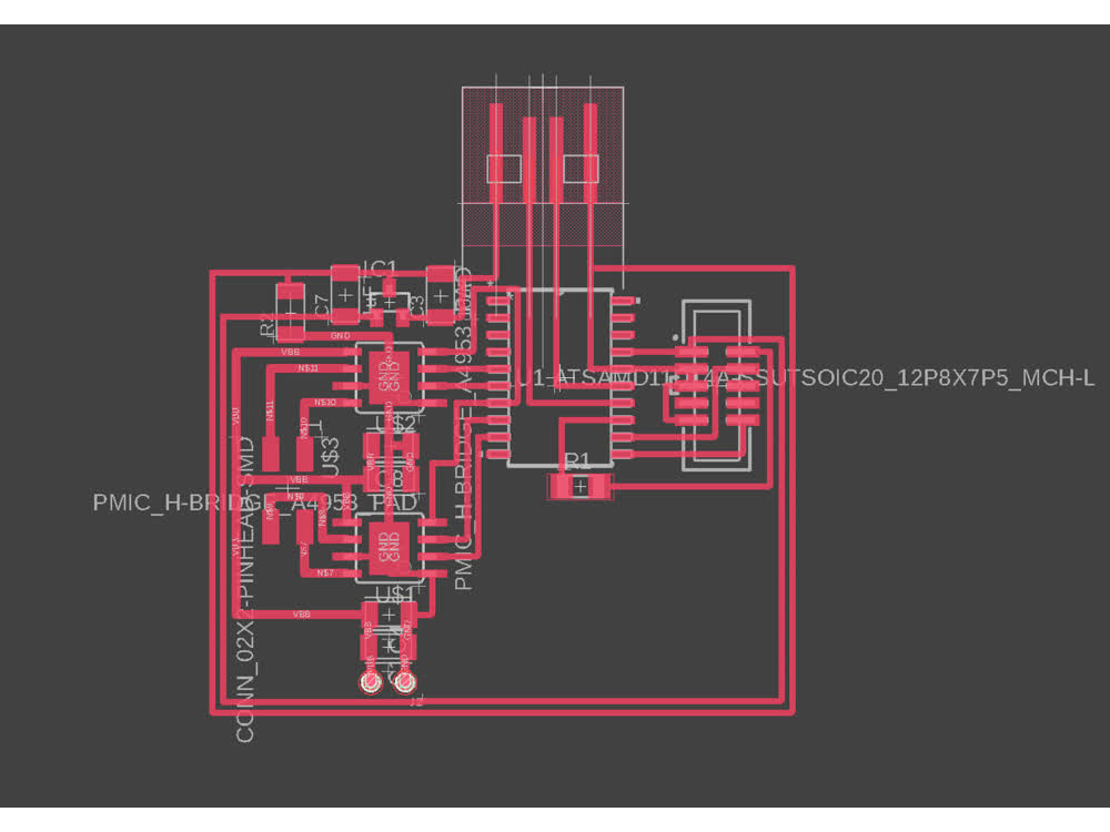 Stepper driver PCB design.
This week I gave the Roland Modela a shot and found it quite straightforward and yielded good results. The stuffed board below was photographed after several rounds of troubleshooting and debugging so it looks a bit beat up.
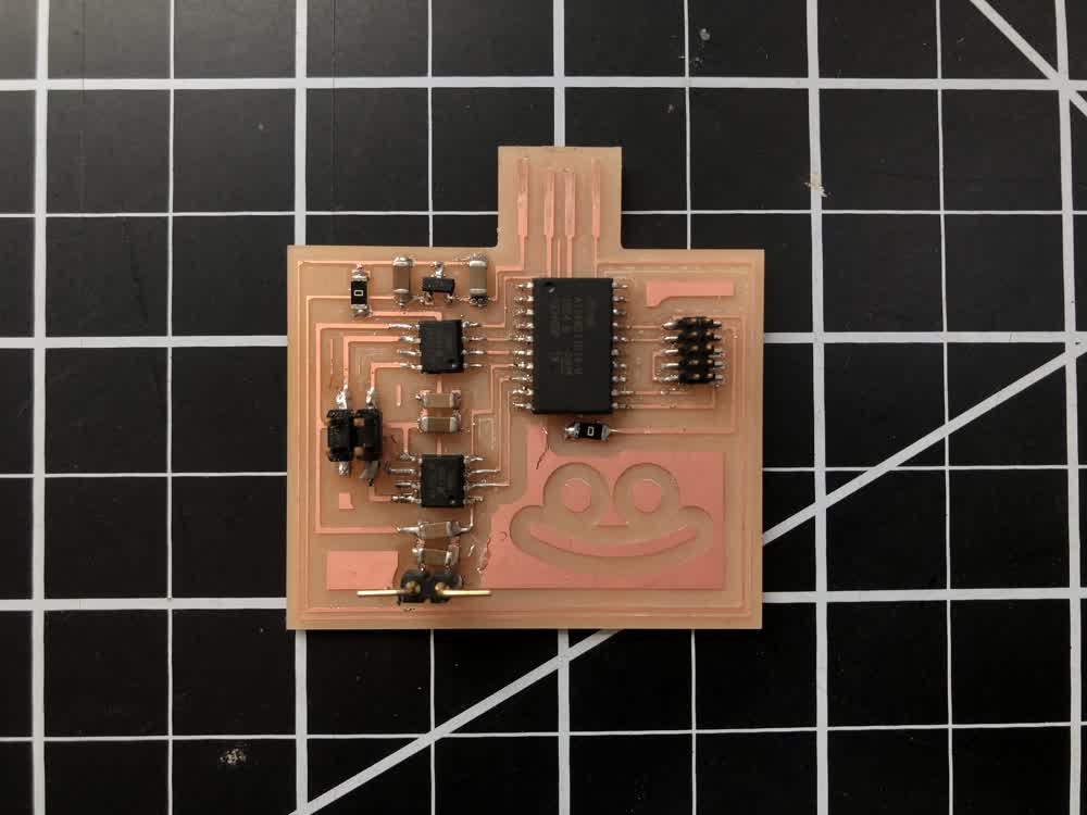 Milled and stuffed board.
After loading a bootloader using edbg I was able to send code to the board from the Arduino IDE over USB. The code I used is really just a simple modification of the stepper library example included with the Arduino IDE.
//This is a modification of the stepper library
//example included with the Arduino IDE

#include < Stepper.h >

 // change this to fit the number of steps per revolution of motor
const int stepsPerRevolution = 200;

//set output pins
Stepper myStepper(stepsPerRevolution, 9, 14, 16, 22);

void setup() {

  //set motor speed
  myStepper.setSpeed(60);

  //setup serial connection if you desire
  Serial.begin(115200);

}

void loop() {
  // step one revolution  in one direction:
  Serial.println("clockwise");
  myStepper.step(stepsPerRevolution);
  delay(500);

}
At first my board wasn't working. I spent a lot of time debugging only to realize at a certain point that the motor I was using was rated for 12V and I was trying to power it using a 9V battery. Face palm.
I tried the benchtop power supply in the architecture shop set to 12V and lo and behold it worked!
Stepper motor stepping!
Though it worked, the movement was a bit inconsistent and strange things happened when trying to rotate both clockwisee and couterclockwise. One remedy might be to include a bypass capacitor between the voltage source and ground.
File: 201116_traces.png
File: 201116_outline.png