Week 13: Networking and Communications
This week I tried to set up two Xbee's to talk to one another. I did not succeed (...yet?) but here's what I've done so far...
XBee's in Serial Mode
I'd been looking forward to this week because I'd like to incorporate networking into my final project. I'd seen lots of Instructables using XBee's so I ordered two of them from Adafruit, as well as two Adapters (links to those are at the bottom of the page). The Adapters make it easy to program them using an FTDI cables. There are lots of adapters out there, but Adafruit also has lots of tutorials, and reasonable 2-day shipping (from New York). Once they got here, I assembled the Adapters and programmed the X-Bee's according to her tutorial (again, all links at the bottom; I'm not writing a new tutorial because hers is very good).
The first thing I wanted to do was: make sure they work at all. Using an Arduino, I had them speak in Serial. Or, the Arduino is connected in serial to the computer and an XBee is connected to the Arduino through Tx and Rx pins. Another XBee is connected to the computer through FTDI cable. Half of that configuration is shown below. You then run an Arduino program (the program is in the Adafruit tutorial) and open its Serial Monitor, and then the Xbee's can talk back and forth! It's like a little gchat. The only snag I ran into was trying to install FTDI cable drivers (this was also the first time I was using Arduino IDE). Pro tip for Windows 7 64-bit users: the FTDI Drivers are in the folder above 'FTDI Drivers' folder.
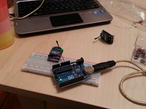
Adafruit Adapter fits handily into a breadboard
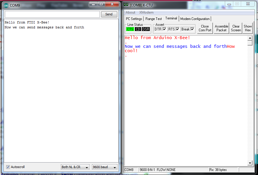
Arduino Window only shows stuff from XBee; XBee Comm window shows both sides
Xbee's talking to one another with Adafruit Adapter
While waiting for my XBee's to arrive, I designed and fabbed some circuits for them, so I'd be ready when they got here. I should have read more tutorials but I just jumped right in. And consequently, these boards were woefully mis-directed. The Adafruit adapters are configuring the boards using X-CTU (the Digi software they use, there's a link below). Their Tx and Rx are for serial mode, and I just wanted to send one's and zero's to turn LED's on and off. Long story short: don't do this with adapters, you don't need adapters to send values. In fact, you can't send Digital I/O with the adapter. Read more tutorials first, Lindy.
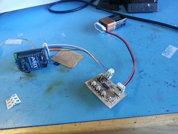
Adapters are for configuring, not for actually using the XBee's. Oops.
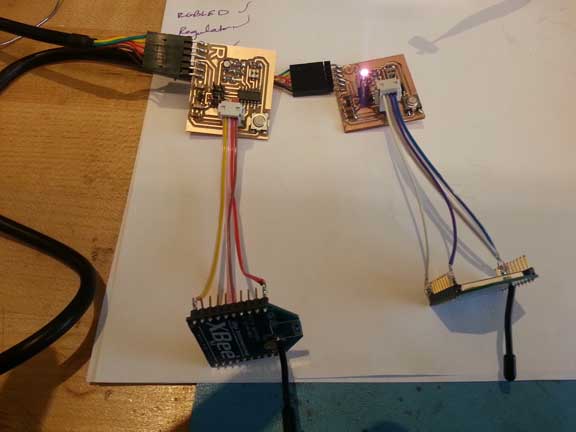
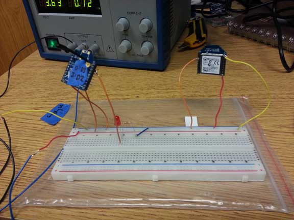
Xbee's talking to each other with Digital I/O
It only took me a few hours to realize I shouldn't be using an Adapter with the XBees's. I needed to hook up to their Digital I/O pins directly. As per, you know, all the helpful examples I'd found. The Adafruit and Jie Qi ones are especially helpful. I made circuits where one microcontroller pin goes to a Digial Input pin on an XBee that is (wirelessly) configured to transmit to a Digital Output pin on the buddy XBee, which is wired to a pin on another microcontroller. I wanted to be able to press a button on one board, and an LED lights up on another. This took a non-trivial amount of planning, since the XBee has to be configured before I can solder some leads onto it. To be clear...
Microcontroller Output --> XBee DIO pin set to INPUT ~~> (radio transmitted) ~~> XBee DIO pin set to OUTPUT --> Microcontroller Input
At first I thought my code must be wrong, or the logic was wrong. I made the program in Arduino and in C. I knew the board was receiving code and could tell when the button was pushed, and was able to turn on the LED. I knew it was changing (pulling up or down) the right pins. But the other XBee didn't seem to be getting the message. So, I decided to make sure I understood XBee configuration by putting them on a breadboard.
Not communicating... one of the lights was always on
Debugging with a breadboard and LED
I thought: I should be able to give both XBee's +3.3V and ground. I should have one Input pin that I can move between ground and Vcc (High and Low), which is configured to change the other XBee's pin to Output high or low. This second pin is connected to an LED. So... I should be able to, on a breadboard, move around one wire (no microcontrollers) and get the LED to light up on the other XBee. Alas, this did not happen. I followed several tutorials, to no avail. There are many values in X-CTU but I think that for most of them, defaults are fine. Some tutorials would talk about changing certain settings that other tutorials didn't even mention. The Adafruit adapters have red 'activity' LED's, and when both boards were powered through the adapters, these LED's were on, suggesting that there was some communication (I think?). I suspect that something is wrong with these settings. Or, alternately, something is deeply wrong with my understanding of Xbee. I really hope it's the former
X-CTU Settings
Multitudes of Gratutitude to who can tell me what's wrong with the configuration
| Setting | XBee A | XBee B | Notes |
|---|---|---|---|
| Baud Rate | 9600 | 9600 | I haven't tried changing this |
| Channel | C | C | This is the default |
| Pan ID | 3137 | 3137 | These must match, taken from Jie Qi tutorial |
| DL (Destination Low) | 5656 | 3434 | Taken from Jie Qi tutorial, DL must match other XBee's MY |
| MY (Source Address) | 3434 | 5656 | Also taken from Jie Qi's tutorial |
| RR (Retries) | 2 | 2 | I decided this should be in the middle... though clearly I have no intuition about XBee's so I don't know why I did this |
| D3 (Digital I/O, pin 17 on XBee) | 5 (Digital Output, High) | 3 (Digital Input) | |
| D2 (Digital I/O, pin 18 on XBee) | 3 (Digital Input) | 5 (Digital Output, High) | |
| IC - DIO Change Detect | FF | 0 | I thought, after reading the datasheet, that both of these should be on, but the Adafruit example only showed the XBee sending data having the FF value. I tried it with both being FF but this did not fix the problem. |
| IA - I/O Input Address | Default - FFFFFFFFFFFFFFFF | Default - FFFFFFFFFFFFFFFF | The Adafruit tutoral recommended changing the receiver's IA to 0xFFFF which would let it accept from all radios. But it wouldn't let me type an 'x' in the box so I couldn't change it. |
| Everything Else | Default | Default | Sorry, I don't know what things are the most important that I might put here, for debugging. |
Conclusion: I think XBee's can be really great. I still want to use them for my final project, I just need to figure out how to use them.
UPDATE:It's too late to try it now, but I think I need a Vref on pin 14 so it knows how to measure HIGH/LOW. I thought that was tied to Vcc by default, and all Faludi examples use Series 2 Xbee's (don't need external Vref) so I guess I missed that... I'll try that and update this page.
A whole bunch of Links
- Things I bought and/or downloaded
- From Adafruit: XBEE Module | Adapter
- X-CTU software (used to talk to and configure XBEE's)
- Resources I used for Setting up Xbee
- XBee Datasheet (Digi)
- Table Comparing XBEE's (if you want a different one)
- Overview of Adafruit XBEE Adapter, and how to assemble it (Adafruit)
- Configuring your XBee (Adafruit)
- Xbee X-CTU settings (Adafruit)
- Jie Qi's excellent Xbee tutorial (HTM(A)A)
- Communicating over Serial with Arduino (Adafruit)
- How to install FTDI drivers so it shows up as serial port (Arduino)
- FYI 64-BIT WINDOWS 7 USERS: the FTDI drivers are not in the FTDI folder, they are in the driver directory (this took me way too long to figure out)
- Arduino-Tiny, core for Arduino (and talking to ATTiny's) (Google Code) this has a helpful diagram of what Arduino calls the ATTiny pins
- Resources for setting up XBee that I found but did not end up using
- Book about XBEE Projects | its MIT library listing (access the book with your MIT Certificates)
- High-Low Arduino Programming tutorial (High-Low Tech, Media Lab)
- XBee Datasheet (Sparkfun)
- Xbee Manual (Sparkfun)
- Building Wireless Sensor Networks (book) (Access with MIT Certificates)
- Xbee and Arduino tutorial (bildr)
- XBee Radio Terminal Program (Processing)
- Xbee examples/projects people have done
- Adam Setapen's Final Project from 2010 (HTM(A)A)
- Jie Qi's Example of two paper cranes communicating over Xbee (HTM(A)A)
- XBEE Basics Tutorial (Trossen Robotics)
- This guy writes about playing with Xbee