Week 8: Computer-Controlled Machining
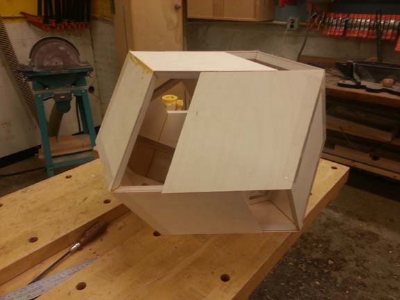
This week I decided to make a large version of my Week 4 (3D printing and scanning) project, like coffee table or stool size. It had been sitting on my desk and I really liked the shapes it made partially opened and closed, and I thought it would be a good exercise for this week. This week's assignment turned into a lesson on what should not be made on the techno CNC.
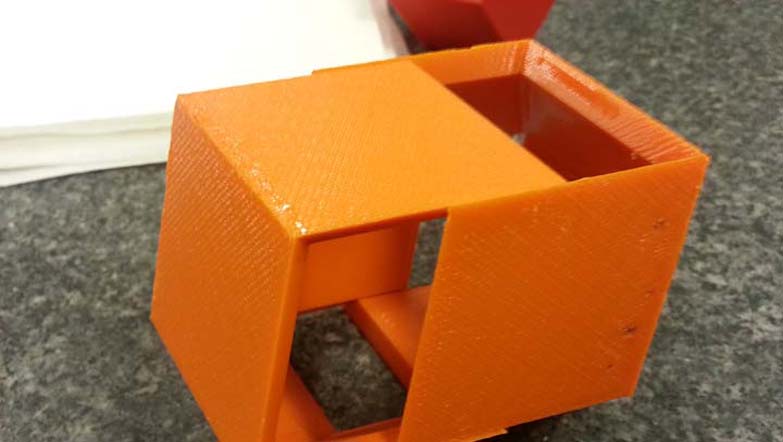
Scaled down version (made Week 4)
The first thing I did was a consultation with Ken Stone in the Hobby Shop, because he always has better ideas about how to make what I want, and because I wasn't familiar with the techno CNC and its capabilities. I'm glad I had the scale model to explain what I wanted. The shape is made of twelve identical rhombuses (acute angle 70.5 degrees, 60 degree chamfer on all sides). It was only possible to make this on the CNC because it has a 30 degree chamfer bit, for cutting out those sides. If those angles were something non-standard, like 70 degrees, this would not have been possible. That should have been my first indication that this project would be better made on another tool.
How I did it
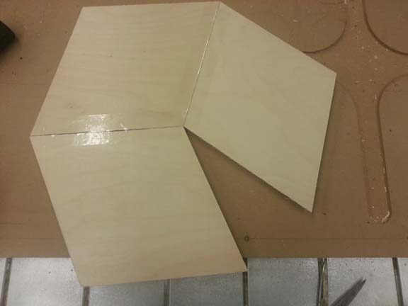
To make the pieces, I only needed to draw the rhombus and then cut it out using the 30 degree chamfer bit. This seemed easy enough, but the project became more complicated because of the bow of the table (and the necessary precision of the pieces I was making, since they all fit together). I couldn't put one large piece of wood and cut 12 times. I had to cut rough pieces first, then fixture them individually to cut them one at a time. I cut them using a really neat Festool table saw, which had a laser!
Blanks were cut using an angle and a tape measure
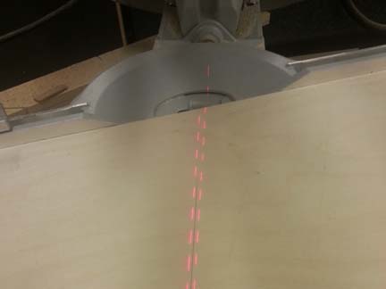
Lasers make everything better
Once the blanks were cut, I fixed them (one by one) to the table using double-sided tape underneath the piece to be cut out, and I nailed down opposite corners on the outside, so it wouldn't fly away once it was cut. This wasn't complicated, but it did take much longer than expected.
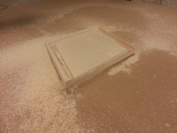
Each of the twelve pieces had to be cut out individually...
I did find a problem when I put the ends together - my CAD wasn't perfect. I'd used the specs from a woodworking book. And I knew it wasn't perfect CAD, but on a small scale (like Week 4) this wasn't a real problem. It was noticeable on this scale
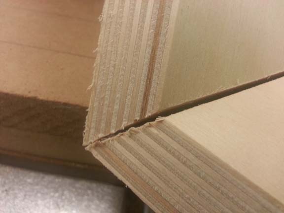
Ruh roh
Because of this, I was concerned about the two final pieces fitting together. So I remade the assembly in SolidWorks to calculate the angle I'd need between the end and side pieces for it to all fit. I made these brackets with a cutout in the middle so I wouldn't be interfering too much with the neat look of the table being partially open. With the brackets, I was able to glue the twelve pieces to make two.
Tape sides together while it's laying flat (if possible), leaving a little gap between
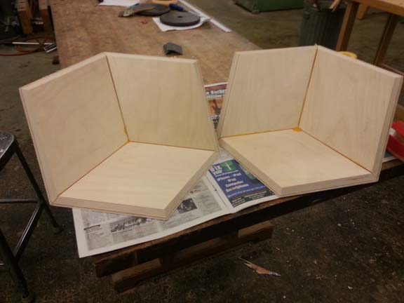
First glue together the ends
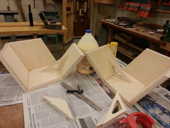
Then, one by one (leaving ~1 hour in between) glue on the sides with brackets
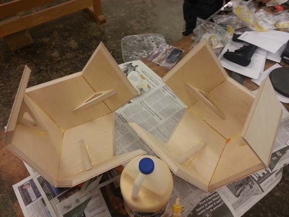
Let final sides sit overnight (24 hours is really best) for full set.
The two pieces in coffee table mode.
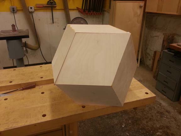
Miraculously, it fits!
I brought it to lab to show off a little (they'd already played with the puzzle a lot)
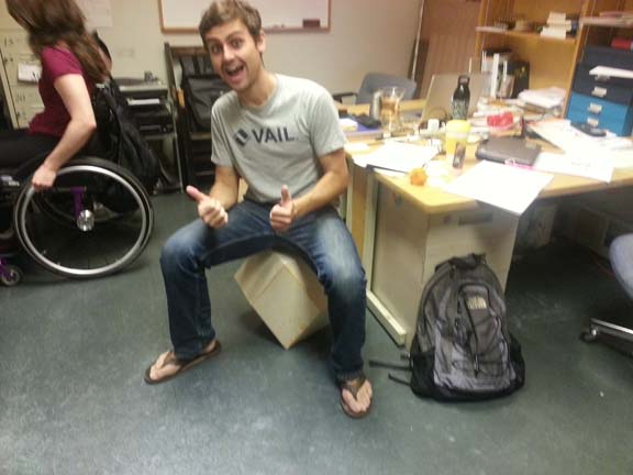
My rhombus stool brings all the boys to the yard.
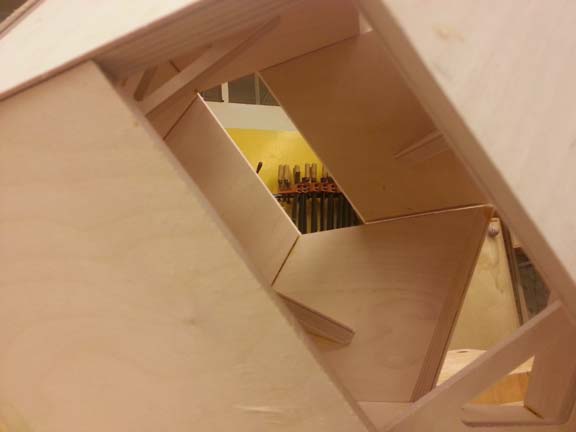
Gratuitous interior shot.
I'm proud of my work, but if I use this shape again for my final project, I will not make it the same way...
How I should have done it
A table saw!! Well, the techno CNC in combination with a table saw. Really, I needed the right tool for the job. And the techno is the right tool for cutting the rhombus shape, but not for making the chamfers. Ken explained to me using a straight bit on the techno for the rhombus, then using this edge to datum off for a fence using the table saw. This would also have let me cut them out on the techno at the same time, which would have saved me an hour or three. Then all angles are done on a table saw, which is also a better use of tools. The chamfer bit was progressively using more of its blade, and cutting both sides of an angle, which wasn't necessary. I did break one bit (a blade) this week. The table saw would only be cutting one side of the angle, so it's a better use of the tools. It also allows me to cut specific angles. And since I know 60 degrees is incorrect from the CAD, I would need the table saw to get the correct angle anyway. Many thanks for Ken for coming up with this procedure.