Week 13: Networking and Communications
Making a BC832/NRF52 Eagle Schematic
I chose to use the NRF52 BLE module attached on the BC832 chip for my final project for two reasons: (1) Wifi seems to consume too much power compared to BLE, which would result in a larger battery and a larger payload for the ornithopter although BLE meets the range requirements; (2) The BC832 has a powerful microcontroller on the chip so that I wouldn't need to program and create room on the board for another module and the traces/physical space required to accomodate that. I also looked at the RN4871, which is just the BLE module without the microcontroller, but ended up deciding on the BC832.
Used Sam Calisch's tutorial for the NRF52/BC832: https://gitlab.cba.mit.edu/pub/hello-world/nrf52 to initially set up and program my board. However, I removed his feature of making the CLK pins into GPIO pins. I also plan to add ports that would connect this board to the camera sensor later on.
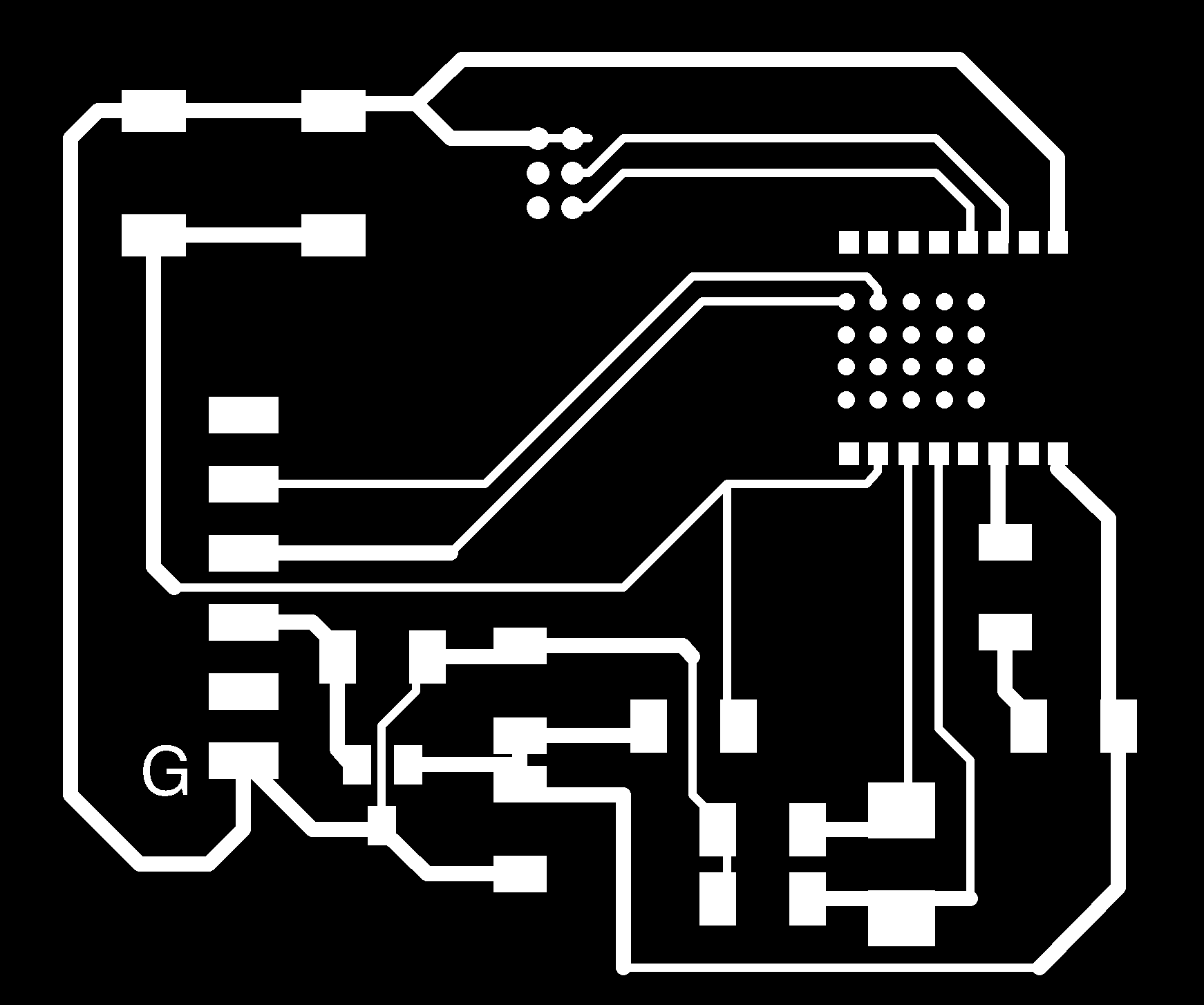
I met a surprising hurdle while creating my board in Eagle: the Eagle LBR file provided by Fanstel was broken or had improper dimensions, so the nets would not snap to the appropriate pins. After lots of searching online, I posted in the Gitlab and Agnes shared the BC832 library that she made while encountering this problem. The new part worked very well, thanks to Agnes! Here are my traces, holes, and outlines:


Due to my retina display on my Macbook, I had some issues with DPI transfer from an image generated through Eagle on my laptop to mods on the lab Linux machines. I export at 1000dpi in Monochrome for the top layer and then export a separate file for the dimension layer + the borders in order to get the holes and outline border. When I put this file on the lab Linux machine, I have to rescale the DPI to 2000 instead of 1000 in order to get the SRM20 to match the actual size or it would print double the size.
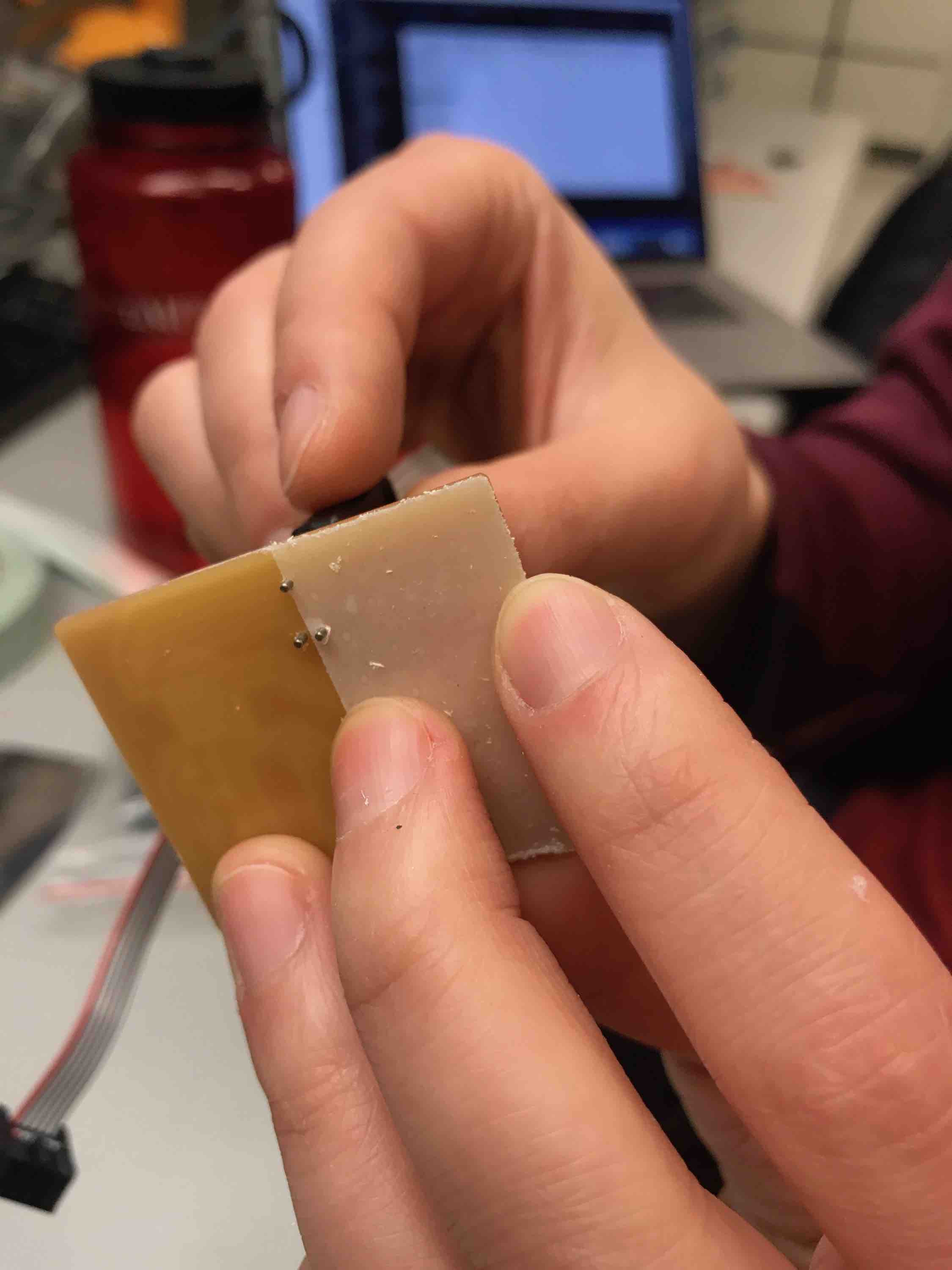
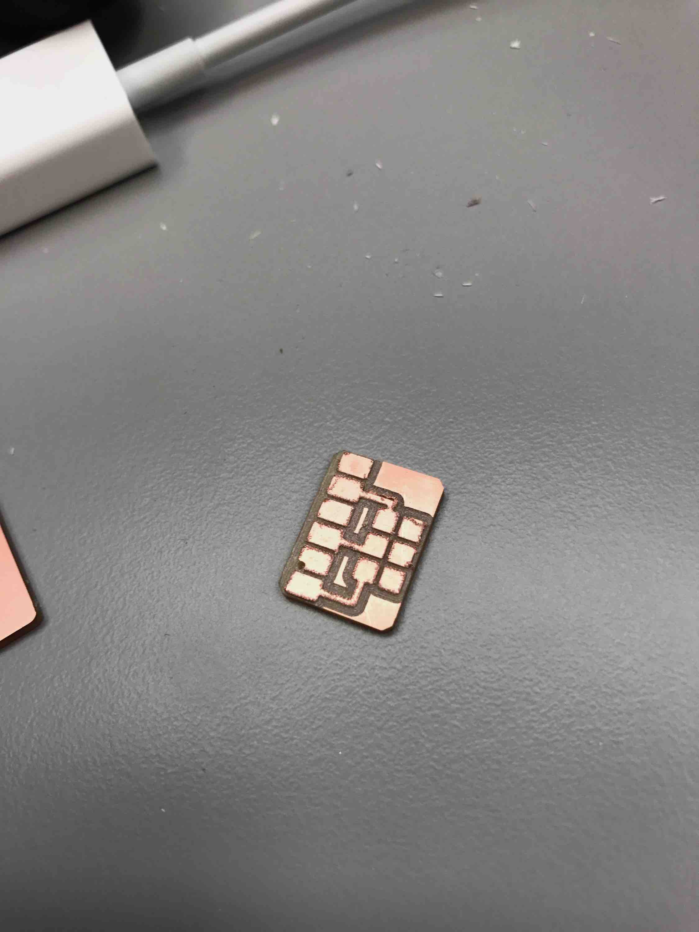
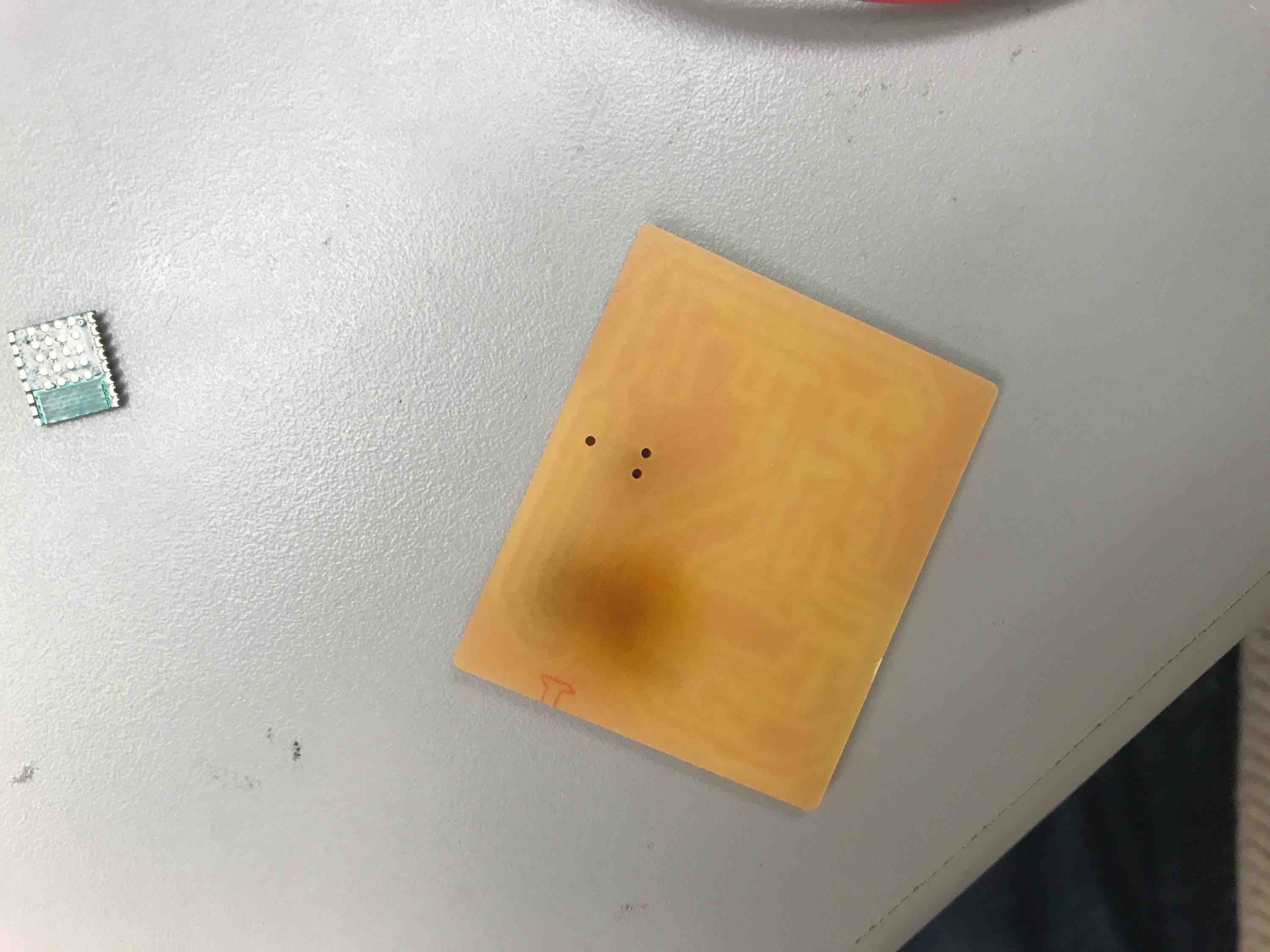
While I have faced this issue in the past, the traces on this board were much more close together than before, so the milling failed to separate the pads of the BC832. We think that it may be because of the DPI ratio issue. At least the holes were big enough for the cable pins to go through.
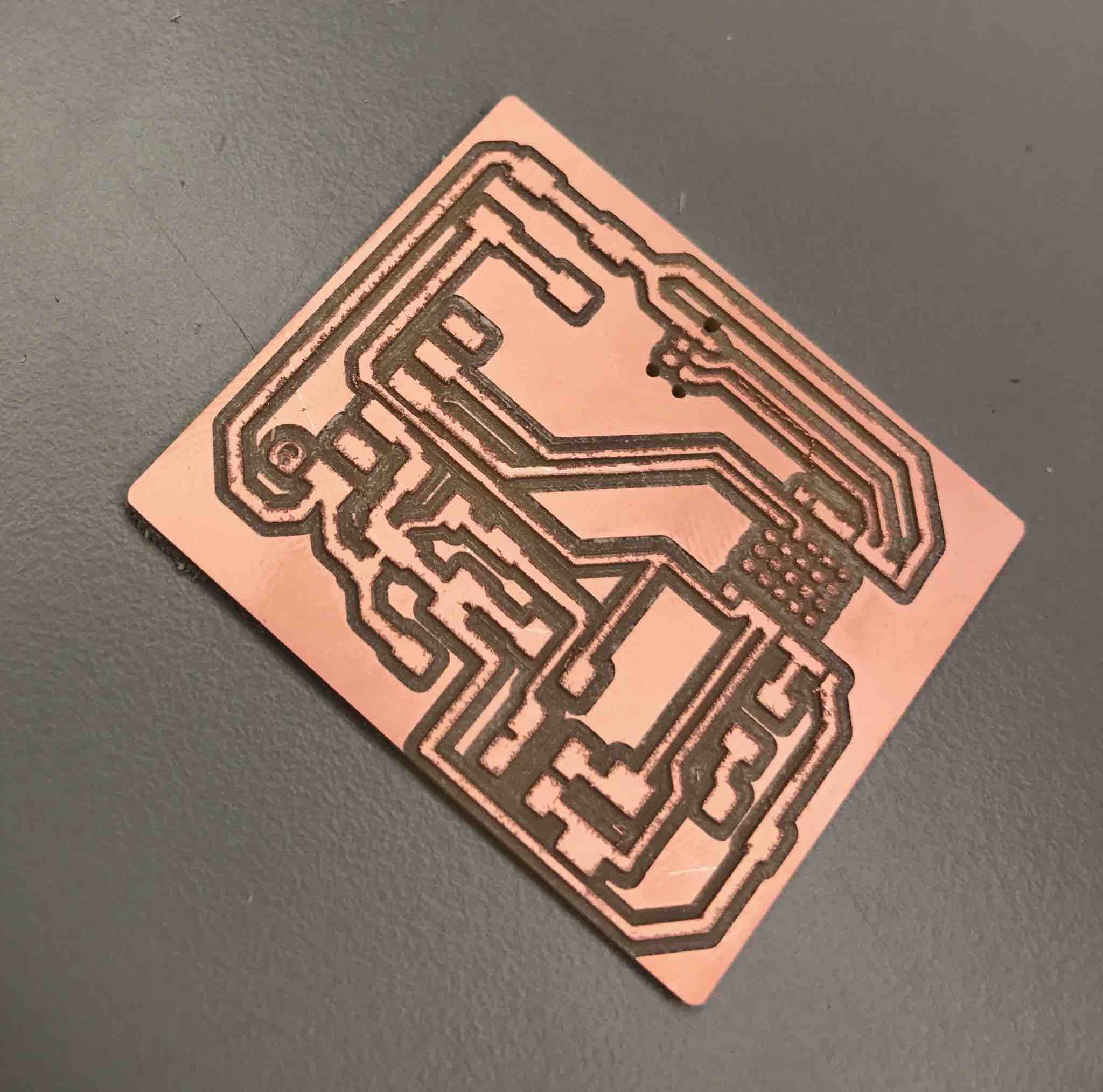
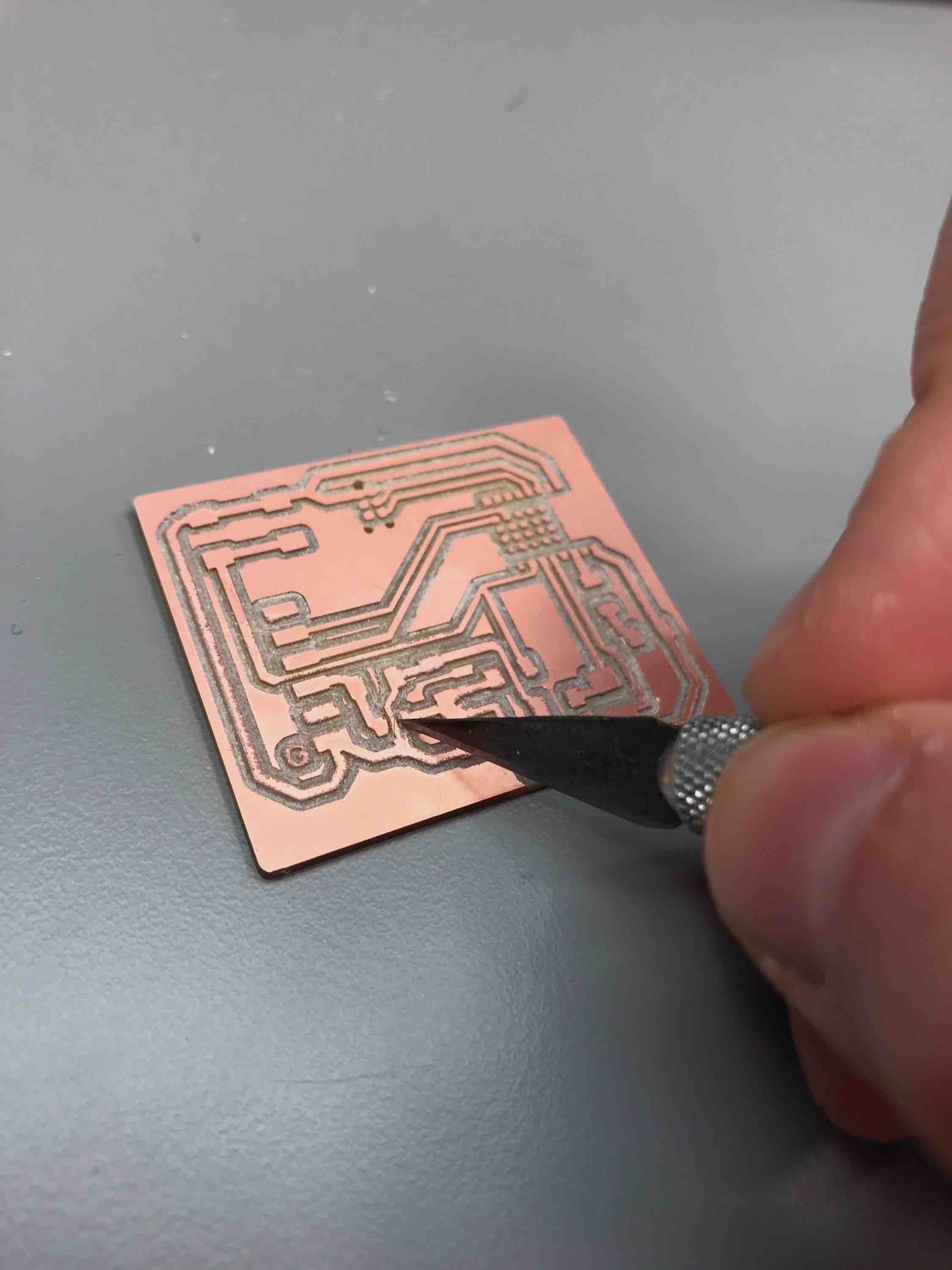
I tried to use an exacto knife to manually separate the traces but that proved to be a bit dangerous, so I lowered the export DPI to 500 to try again. That still didn't work but 250DPI did - with the exception of two small pieces that I needed to cut out with a scalpel.
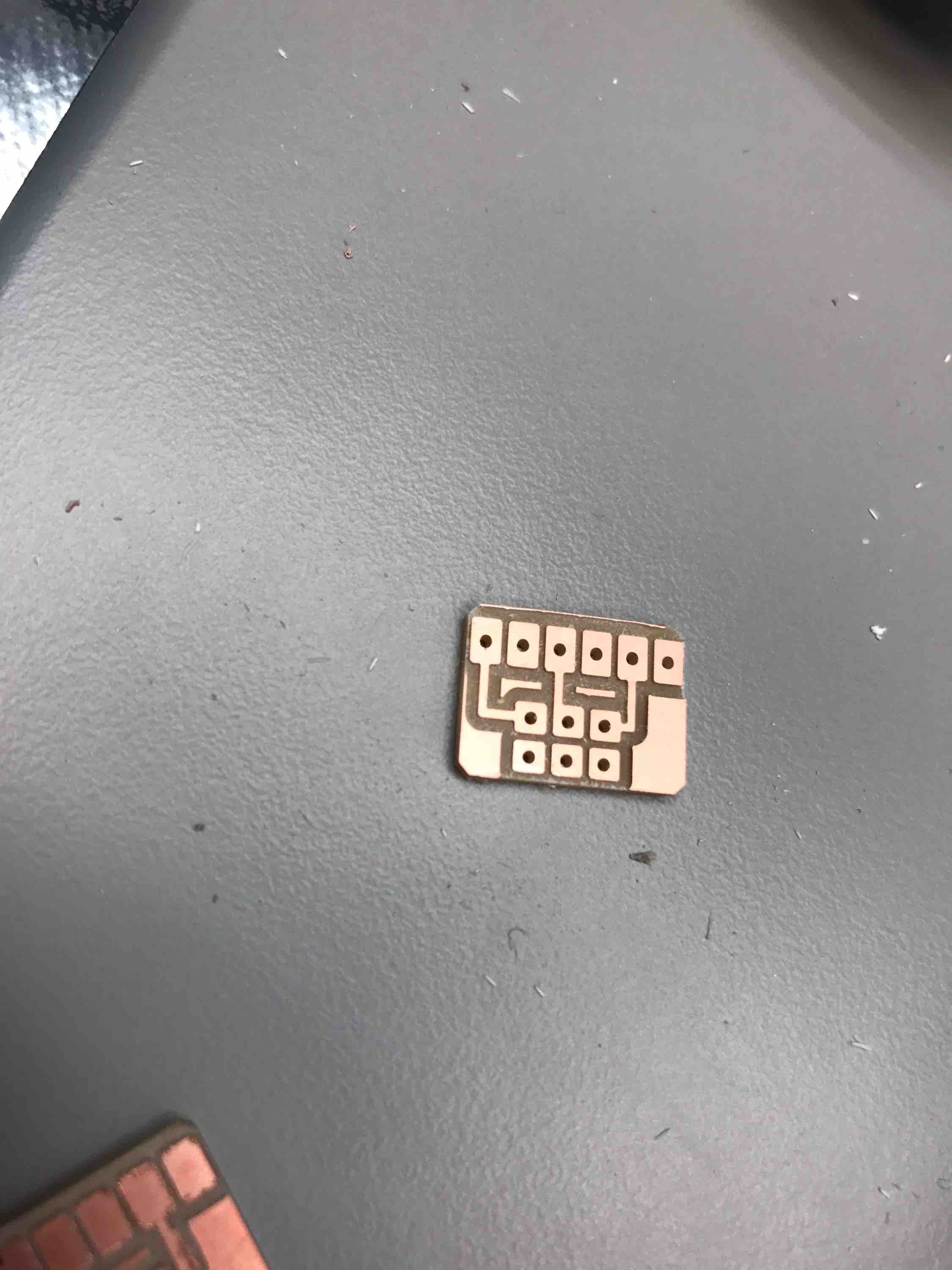
I also had to mill the helper board for connecting the target board to the Raspberry Pi. I just used Sam's traces and outlines files from the tutorial instead of recreating my own, since I wasn't making any modifications. The first time I tried this, the holes and border outline were combined into one file and the SRM-20 decided to cut the outline before cutting the holes. This caused the board to be picked up and the holes were not drilled (aside from a tiny one you can see in the corner).
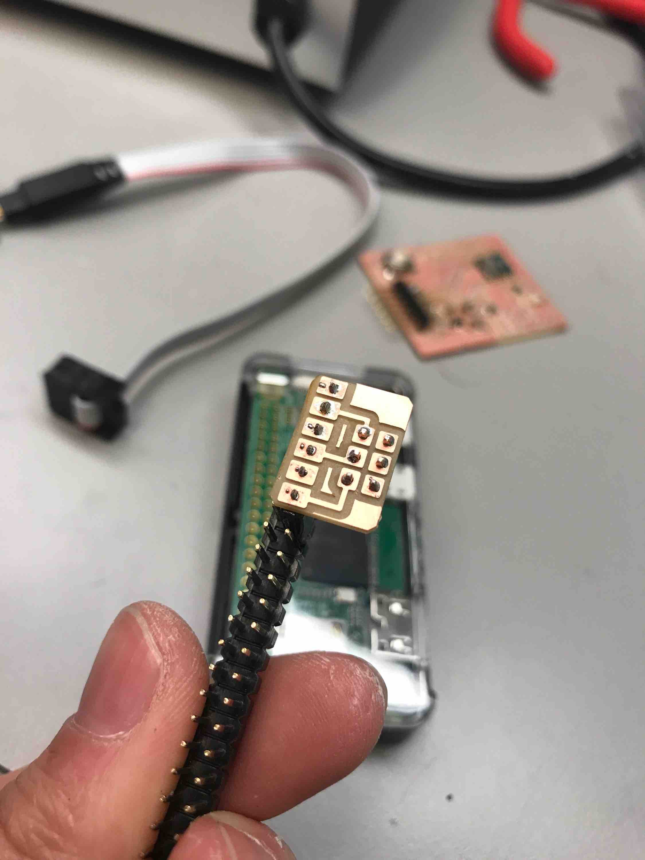
The second time, I separated the holes and pins into separate files and made sure to manually have the SRM-20 drill the holes first before inputting the outline file. The final output looked good and fit well into the provided Raspberry Pi headers. We stuck the header with the connector board using a bit of solder.
Protips:
- In the future, DELETE (black out) unneeded holes/pads on the bottom of the BC832 so the mill doesn't waste time.
- If select all layers, can move the edges of the board file to shrink the size.
- Hole cutting has to be color-inverted so it cuts from the inside and the hole is not larger than it is designed to be.
Soldering with Back of Chip Pins
I wiped down my board with alcohol and used the solder paste and heatgun at 370 Celsius to solder on the BC832 since the small pads on the bottom of the chip looked extremely difficult to hand-solder. This was my first time using the heat gun so I didn't have great temperature control and almost burned part of the board, but it looked like it turned out ok.
However, I tested whether the bottom soldering pads were properly connected and realized one of them was not. I tried to heat up the area some more but it didn't help. I also tried to use the heat gun on the backside to remove the board but apparently heat doesn't transfer through the back (I burnt the back in the process of doing so!). I also couldn't use the grippers to remove the chip since it was connected with solder on the back.
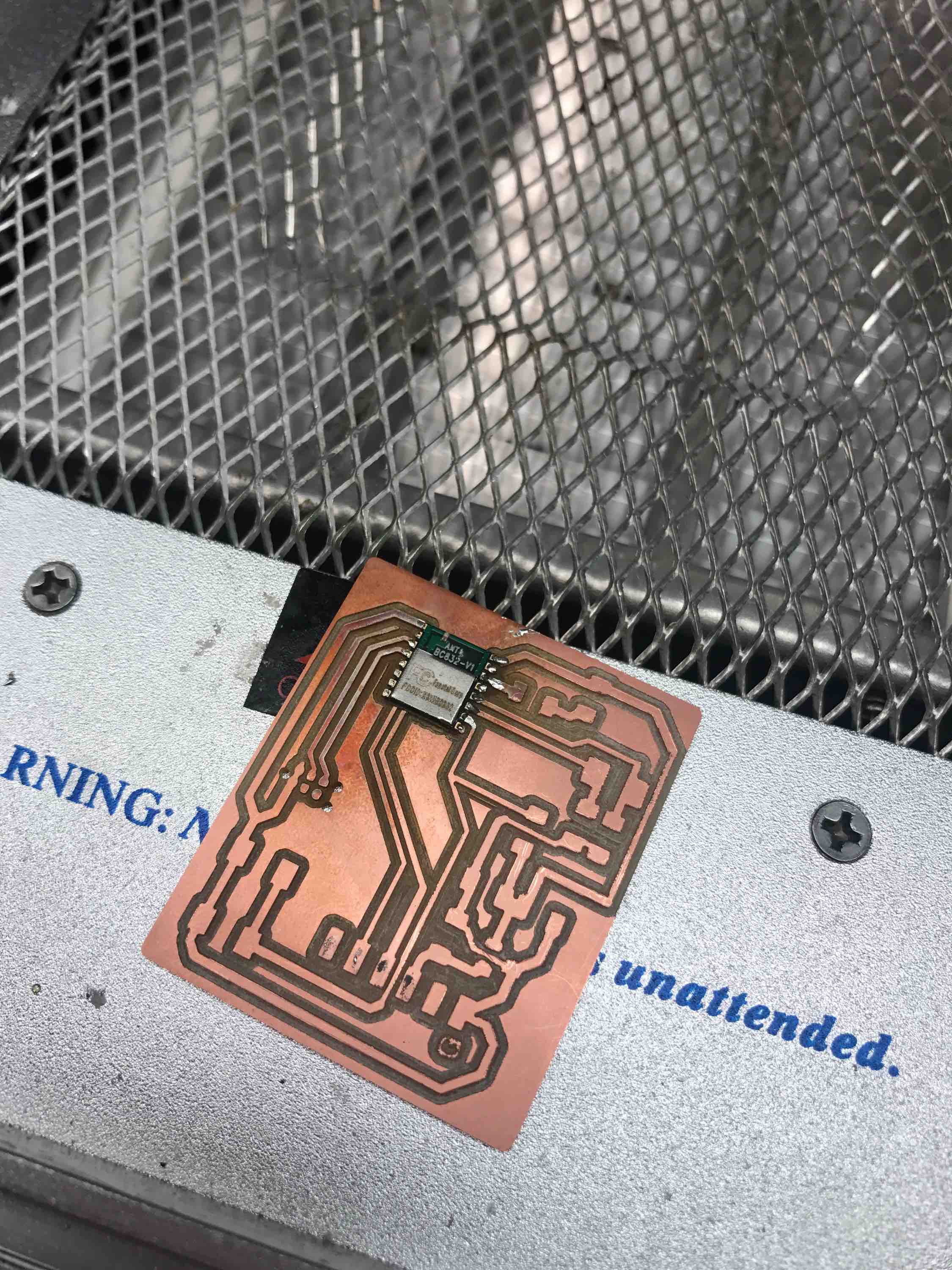
My hypothesis is that I didn't have enough solder paste on the bottom pads. Since I couldn't remove the chip, I ended up milling another board. I made sure to put plenty of solder paste on this time and the chip seemed to have been soldered on correctly from some probing that I did.
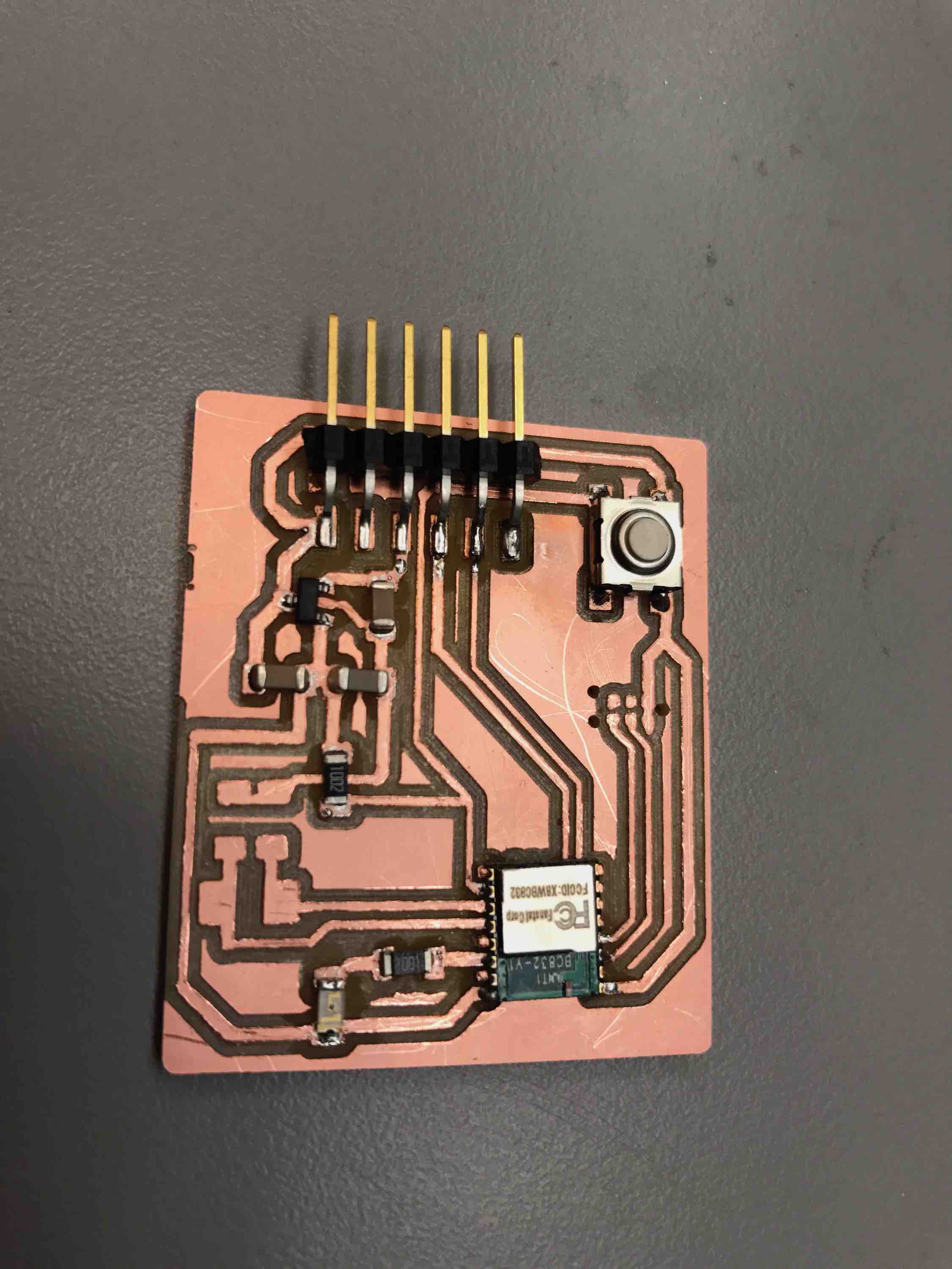
I finished soldering on the other components. Here is the completed final target board after 3 tries:
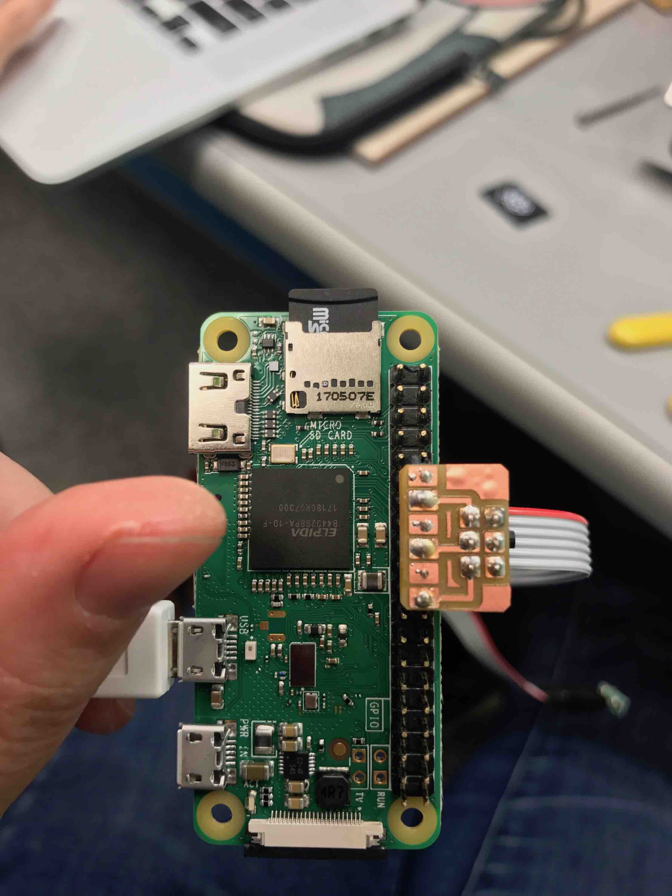
Creating an OpenOCD Programmer Using a Raspberry Pi
Alexandre Kaspar and I attempted to follow Sam's tutorial to use OpenOCD to make a Raspberry Pi bit-bang the programming protocols onto our target board. This would essentially turn the Raspberry Pi into a programmer similar to the USB-programmer we made in Week 3 so that we would be able to set up our target boards to be directly programmable via FTDI-USB through our computers.
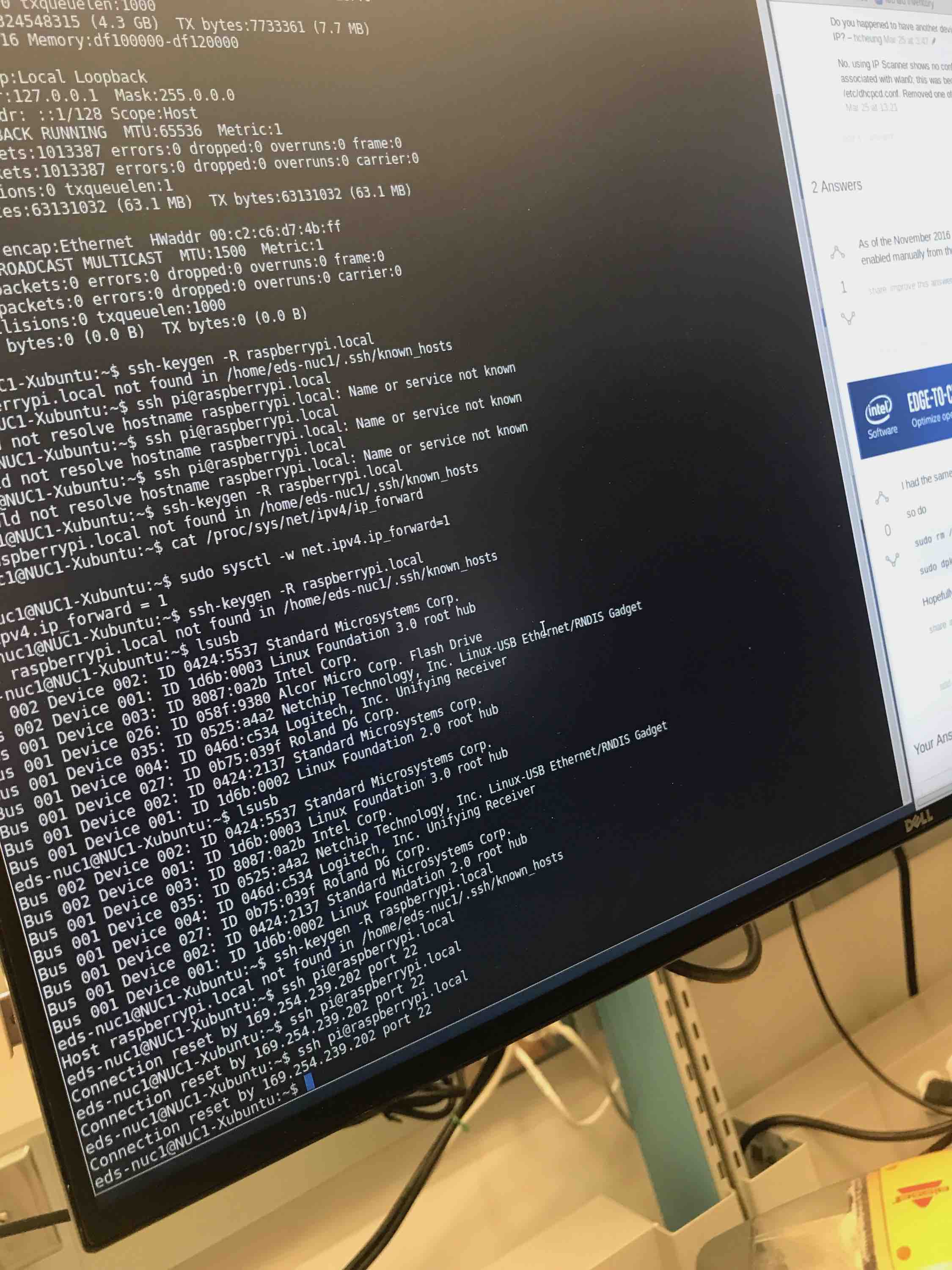
We were initially unable to SSH into the Raspberry Pi Zero W's SD card from our Macbooks or the lab Linux computers. The computer would take a long time to connect or not connect at all, and when it did do something, it would say "Connection reset" seconds later. The generic Raspberry Pi passwords offered on online forums were also rejected.
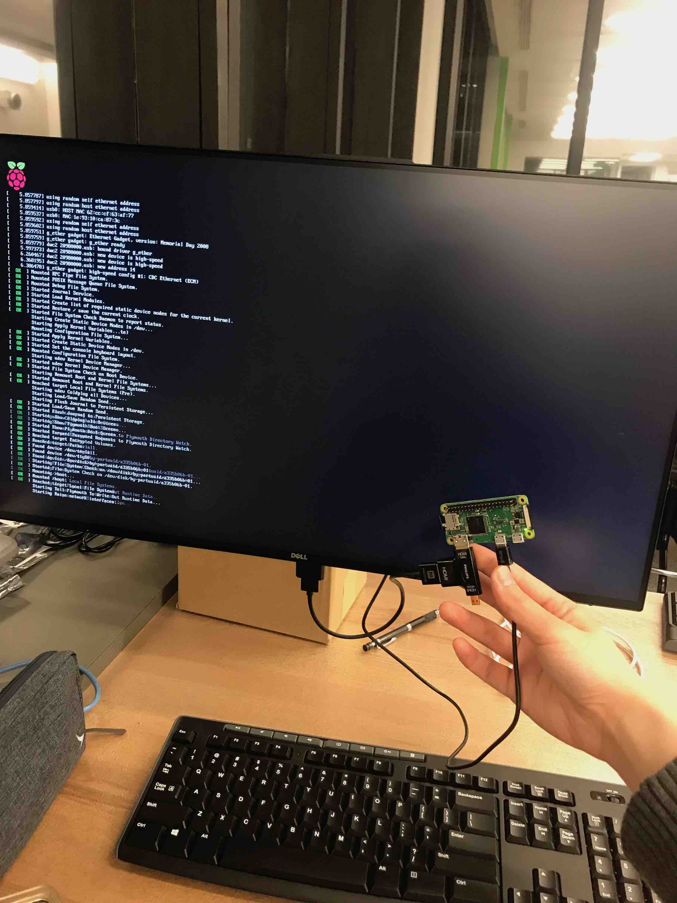
We attempted to directly connect to the Raspberry Pi through a monitor to program it. While Gavin was able to help us find a mini-HDMI cable to connect to the monitor, we were unable to obtain the necessary adapters to connect a keyboard to the micro-USB ports on the Raspberry Pi. We could see the outputs but were unable to input typed commands.
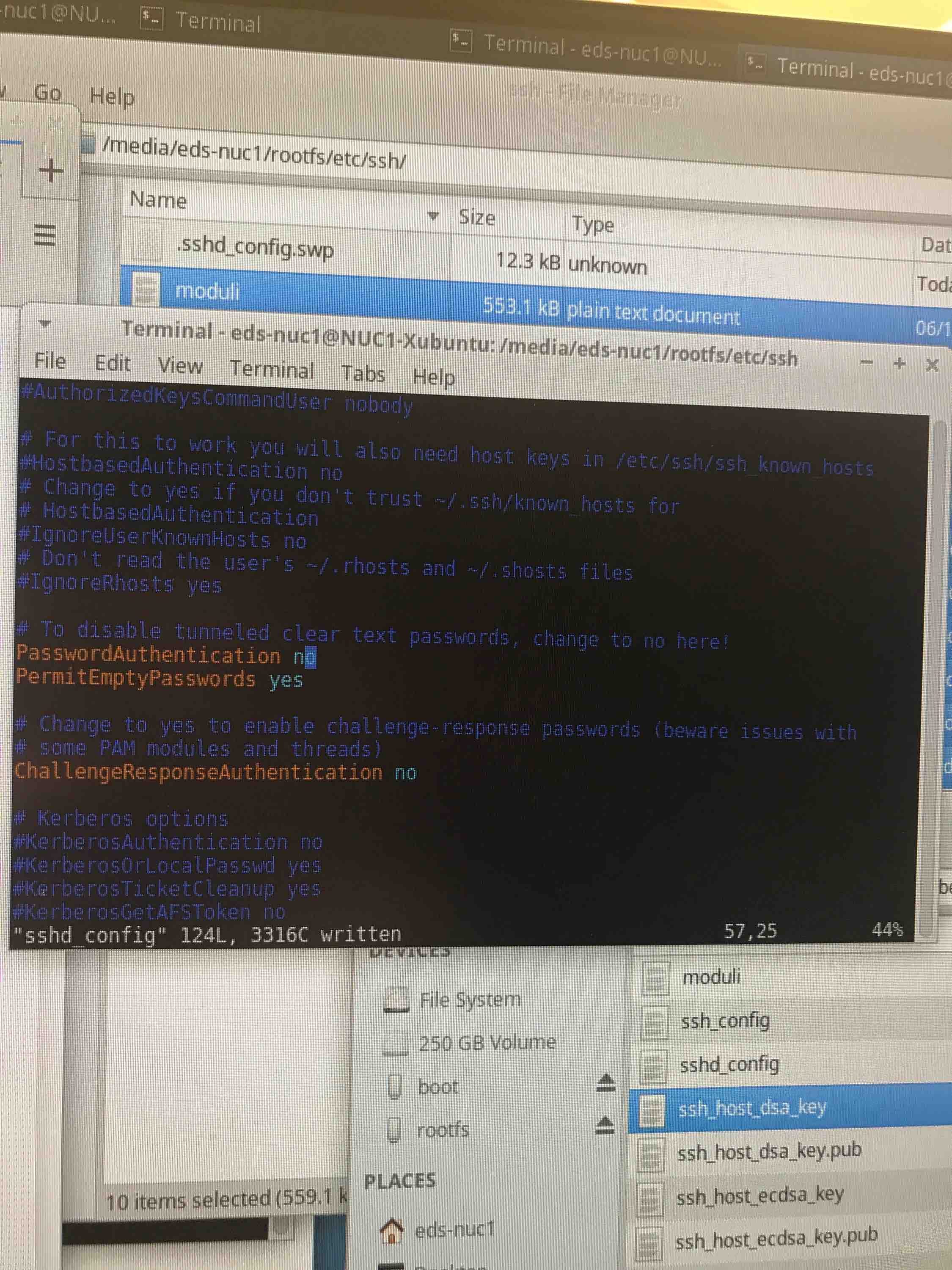
We then tried to disable the authentication (turning off the fields that require passwords and reject empty passwords) and we also tried to generate a public key to prevent it from rejecting our access attempts. The public key embedding hackish method worked, but only on one of our Macbooks and only for one USB port (for some reason the other USB ports would immediately reset connection with the connected device).
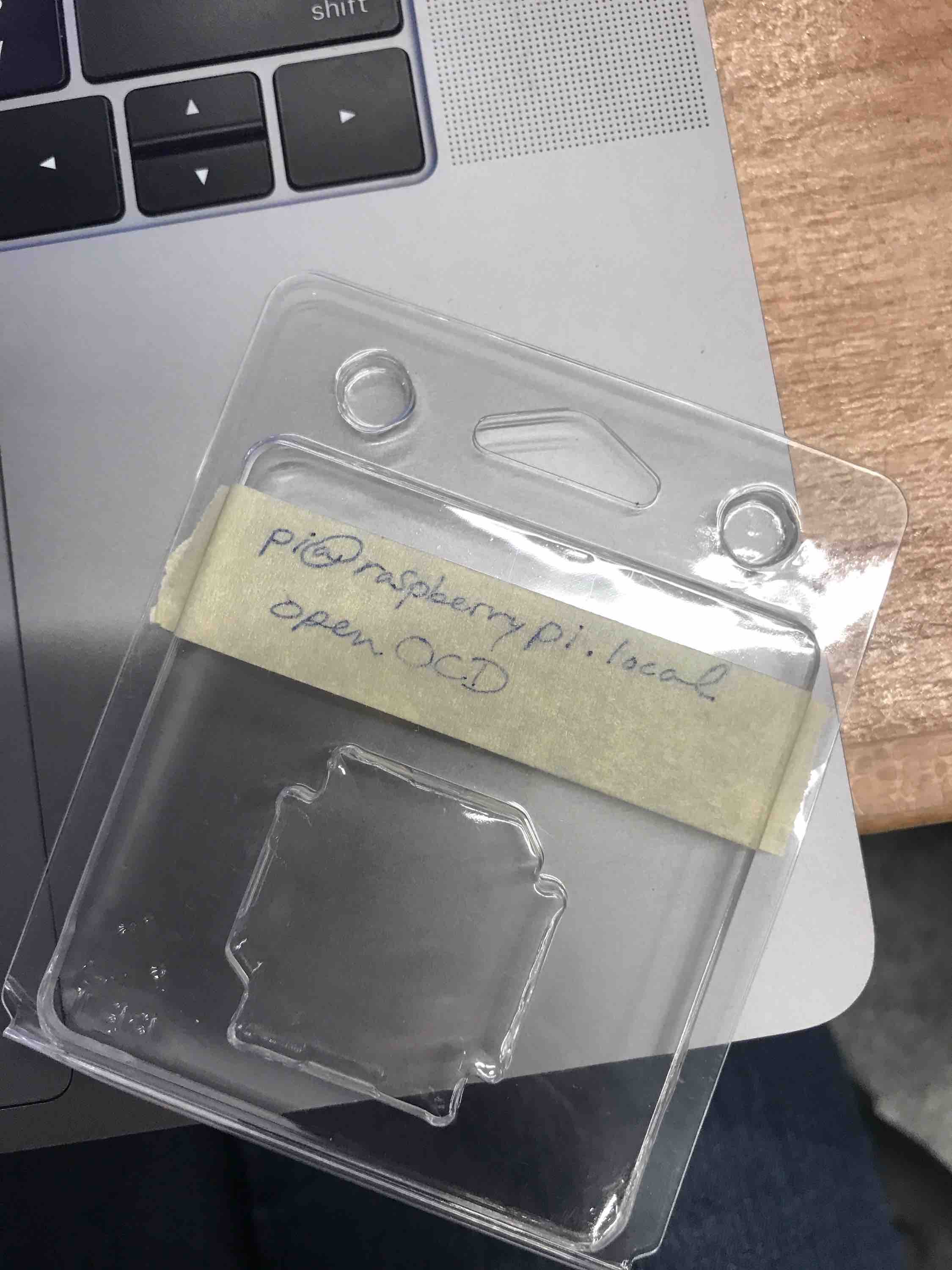
It actually turned out that the SD card given to us had been pre-programmed to work out of the box. We also missed that the password was written on the SD card case, which explains why the common/default password we found on the internet didn't work.
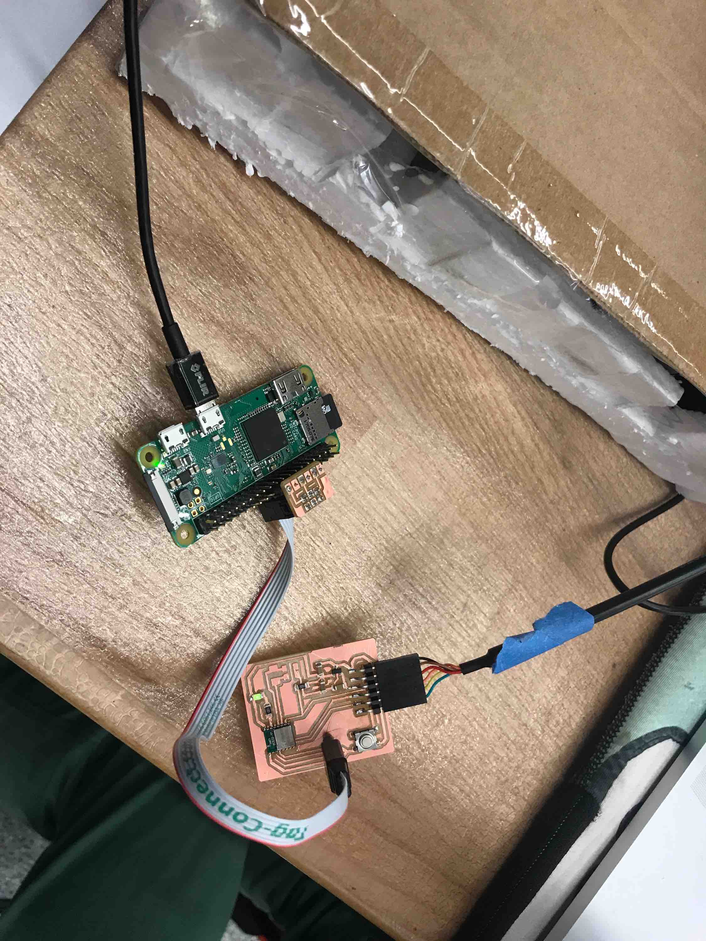
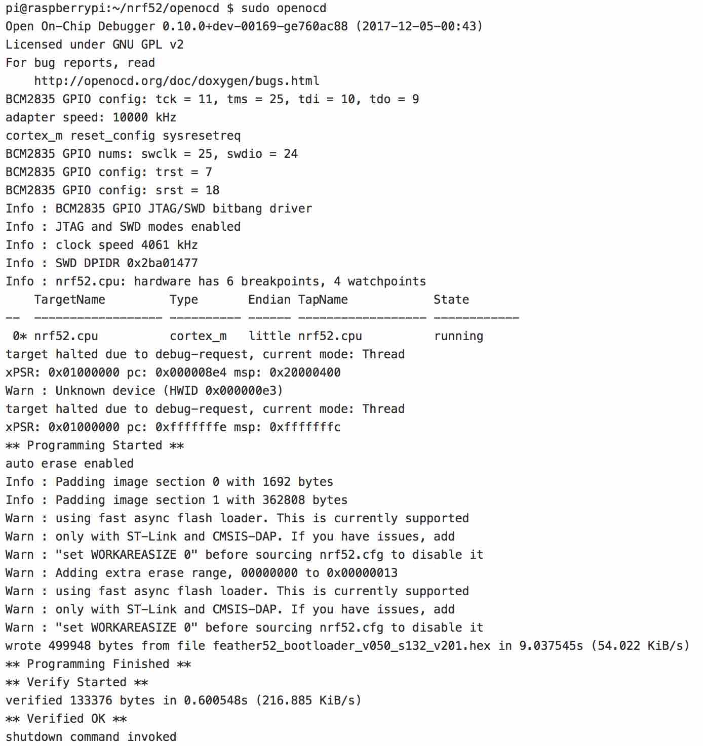
Sadly, we overwrote the card during our attempts at breaking in, so we had to redo all of the building and setting up the Pi from scratch. It was pretty exciting when it finally succeeded in compiling and programming the target board! The trickiest part about the connection was making sure that the header pins and connector were in the right place.
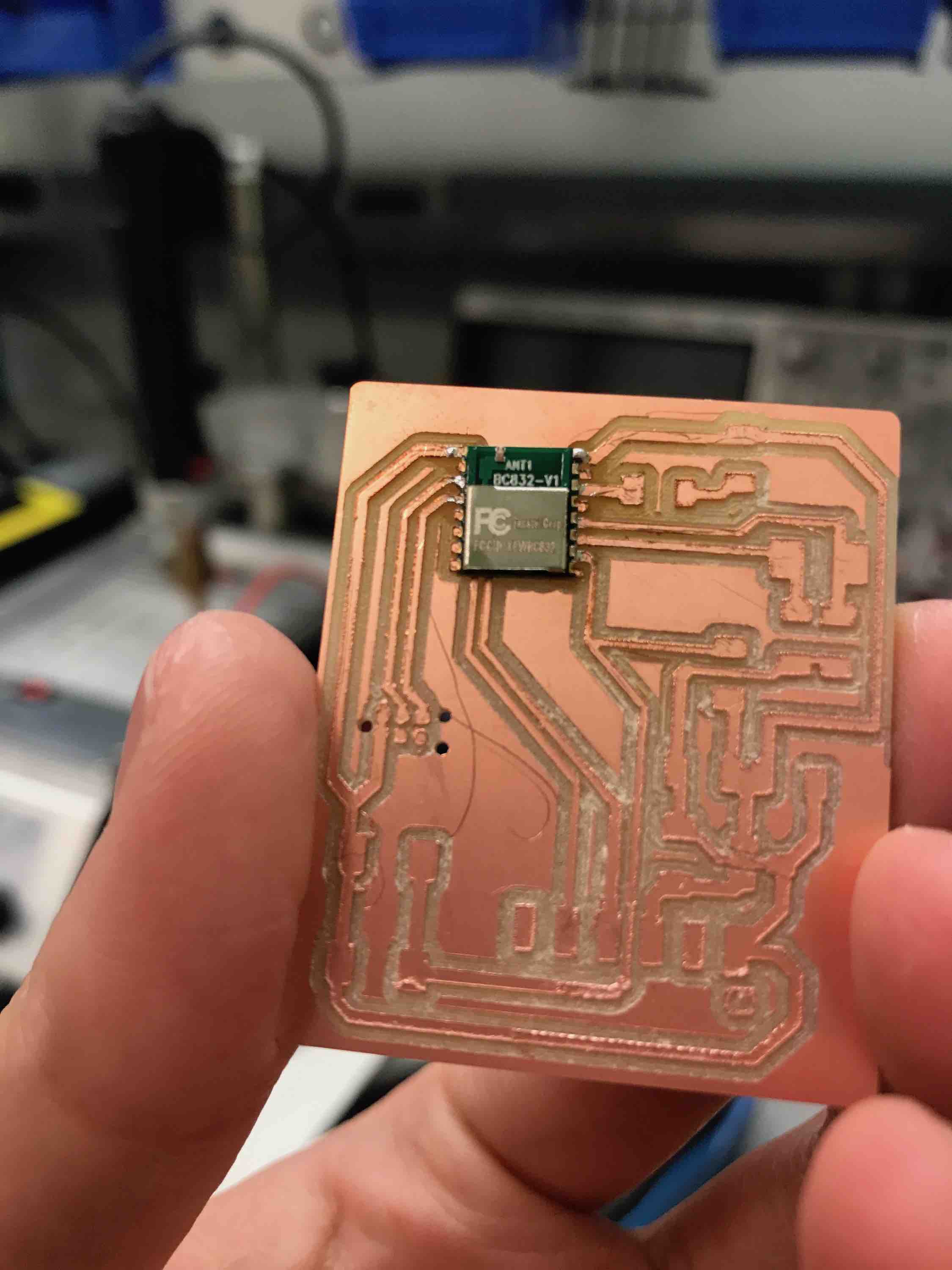
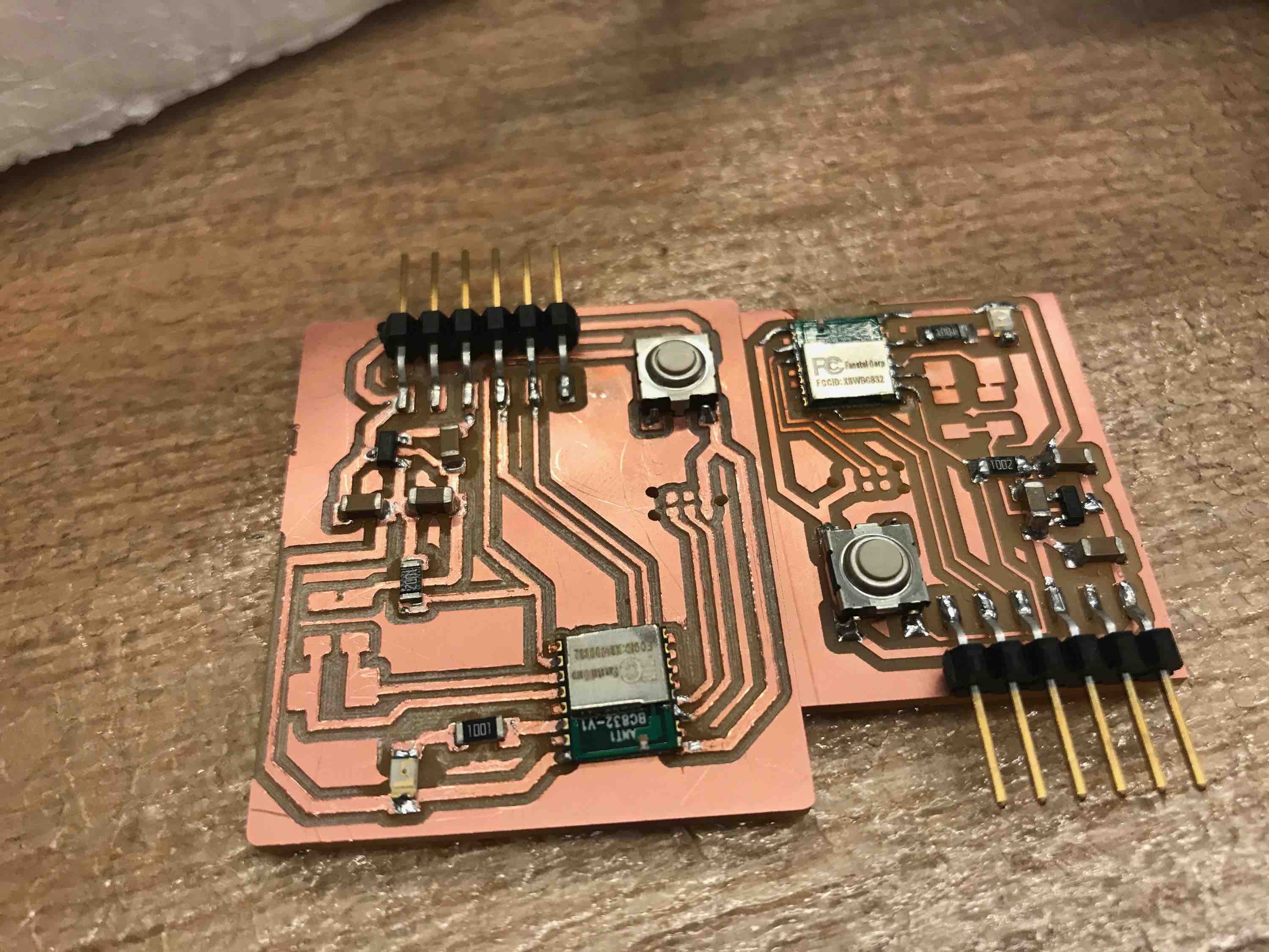
We were actually only able to successfully program the target board that I build, and not Alex's target board. After some probing, we saw that the voltages on his board were higher than 3.7V (the maximum operational voltage for the BC832 according to the datasheet). This may have been due to his traces being much smaller than mine: since the copper channel was so small, perhaps the voltages had to be driven higher in order for the same amount of current to pass through? Neither of us are electrical engineers, so this is probably a bad hypothesis. Nevertheless, here are the two boards for comparison below:
Sam helped us a lot throughout this process, as shown in this thread: https://gitlab.cba.mit.edu/pub/hello-world/nrf52/issues/13
Programming the BC832
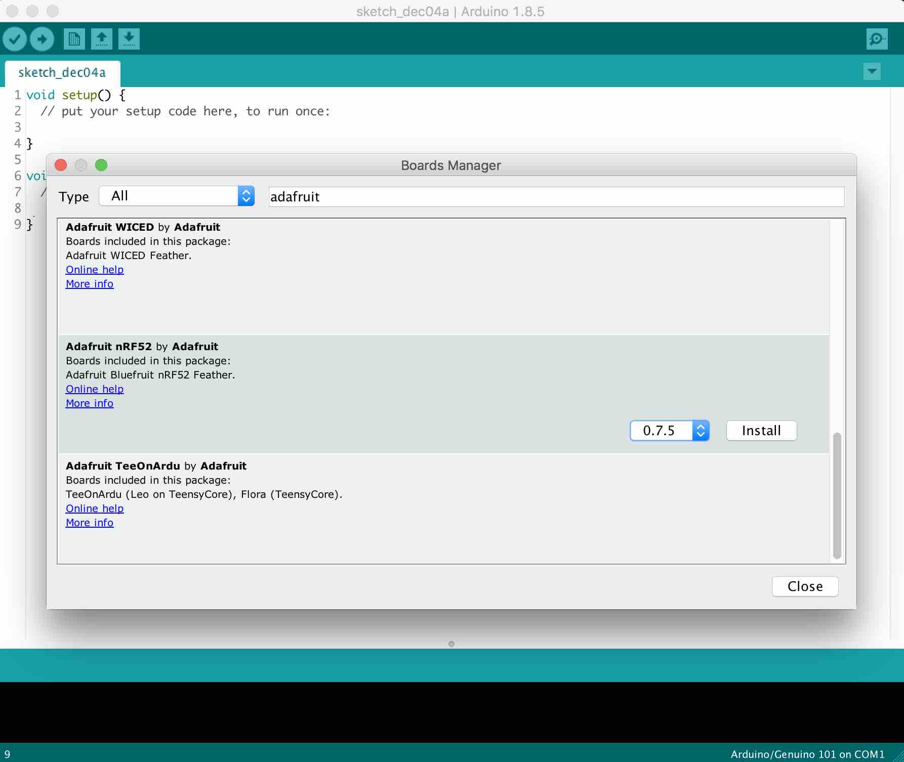
We were still able to program on my one target board. So we followed the steps on this website, stopping at the Bootloader since we already used the feather, to set up the Arduino IDE for programming the Adafruit NRF52832/BC832: https://learn.adafruit.com/bluefruit-nrf52-feather-learning-guide/arduino-bsp-setup
Note: During the step here, you need to have an USB to FTDI cable connected or the appropriate Tools -> Port option will not appear.
We started by loading some very basic hello world code. While the code was very simple, getting it to load onto the target board was a little finicky. We had to press the RESET button on the board immediately after the red colored "Upgrading the target..." text appeared in order for it to program successfully. This was extremely hard to get right and we had to do a few tries before we got a feel for the timing.
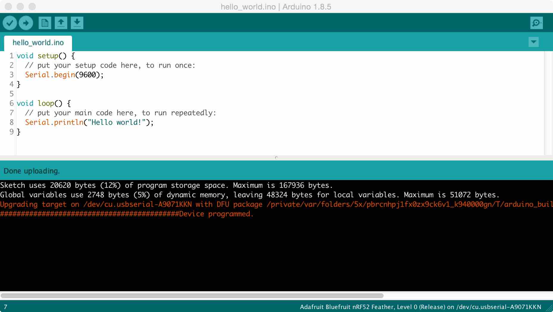
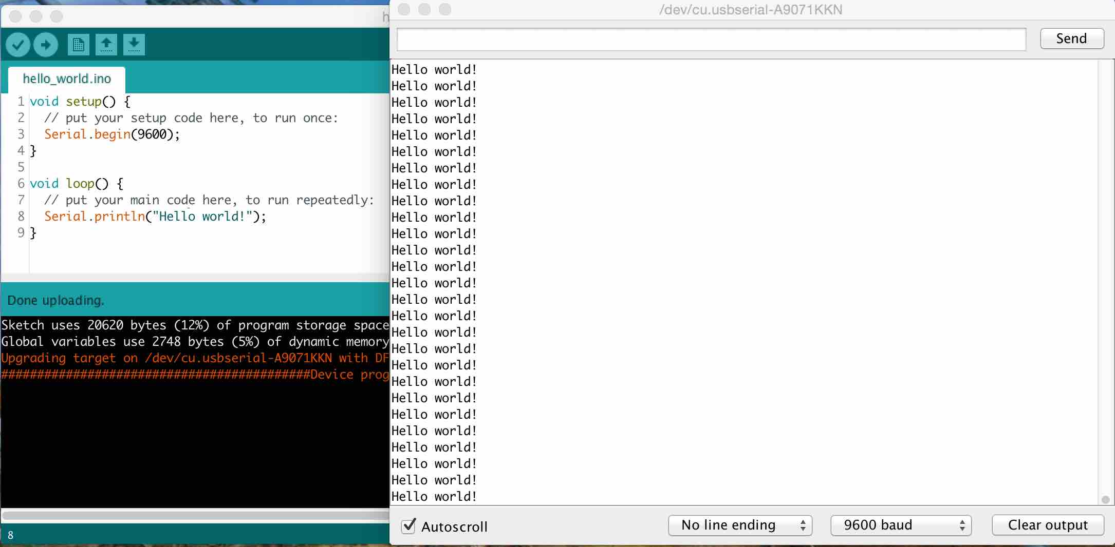
When the code finally worked, we were very relieved. At first, it outputted gibberish, but we then realized that when receiving outputs, the BAUD should be set to the same value as the Serial.begin frequency. This fixed our gibberish issue and we got the nice "Hello world!" text that we wanted from the BC832.
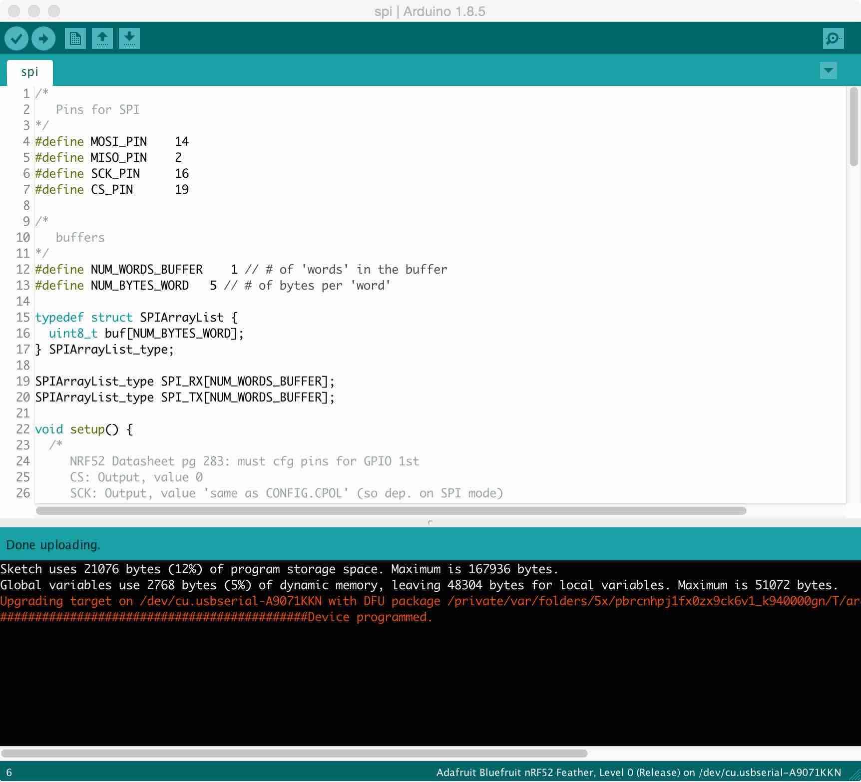
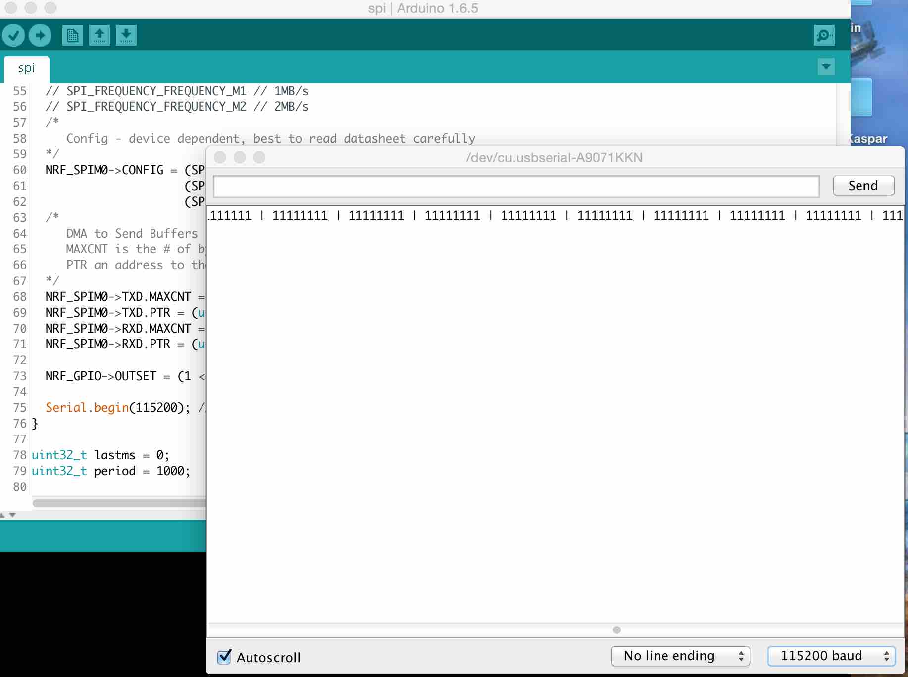
We then tried running the slightly more complicated SPI.INO code. Note that you have to hold down the RESET button on the target board again after successfully loading the program on to start broadcasting. We successfully got the desired output.
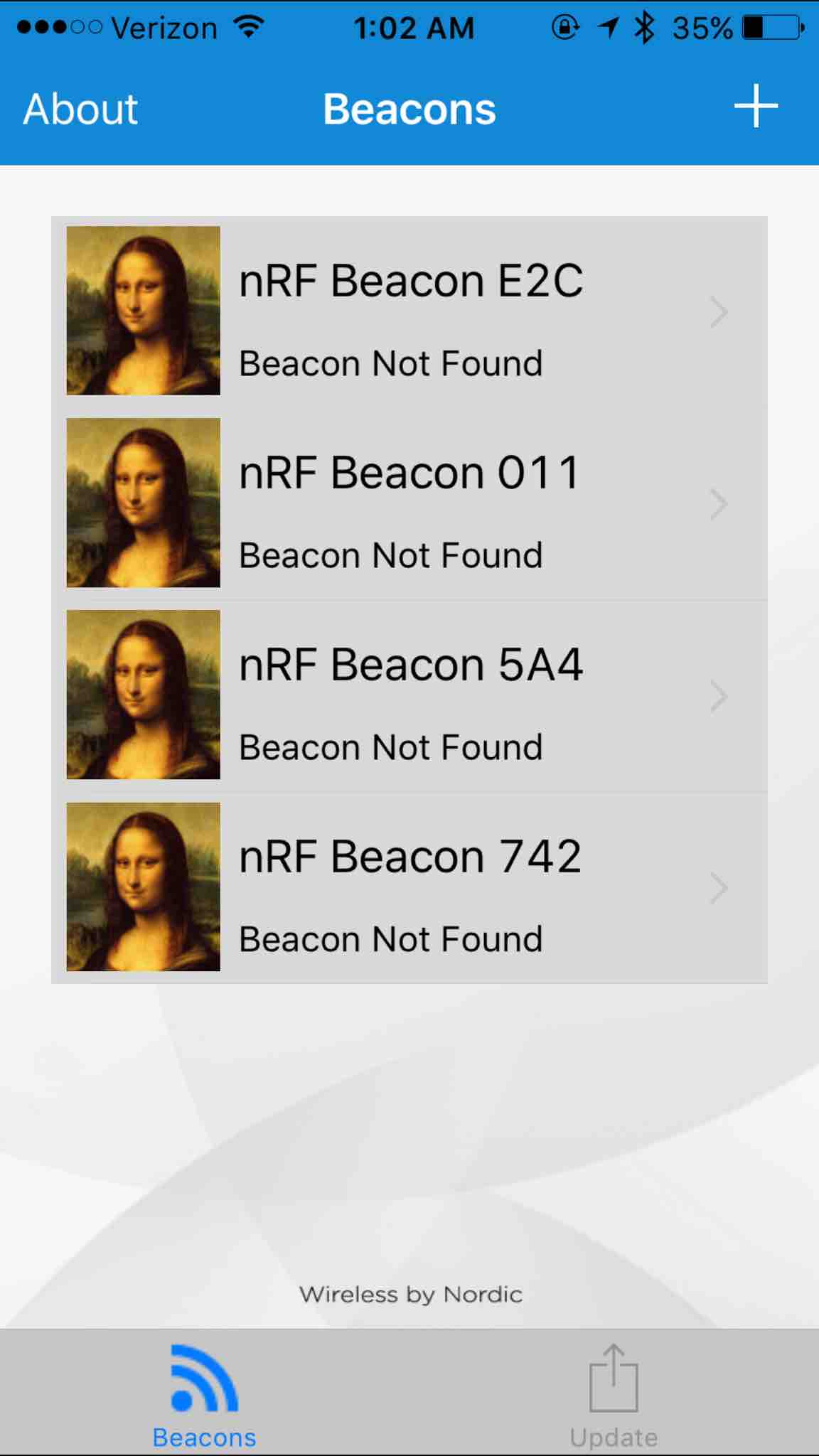
Finally, we tried to run the BLE Beacon code provided by Bluefruit in order to test the wireless communication abilities of the chip. I downloaded this nRF Beacons app from Nordic Semiconductor for my iPhone to catch the signal being outputted by the chip: https://itunes.apple.com/app/nrf-beacons/id879614768?mt=8 To use the app, I pressed "Add Other Beacon". Per the code, the UUID had to be set to "E2C...". I kept Major and Minor at 0 and set the Event as "Near". I also created a few other Beacon settings in case the UUID was different.
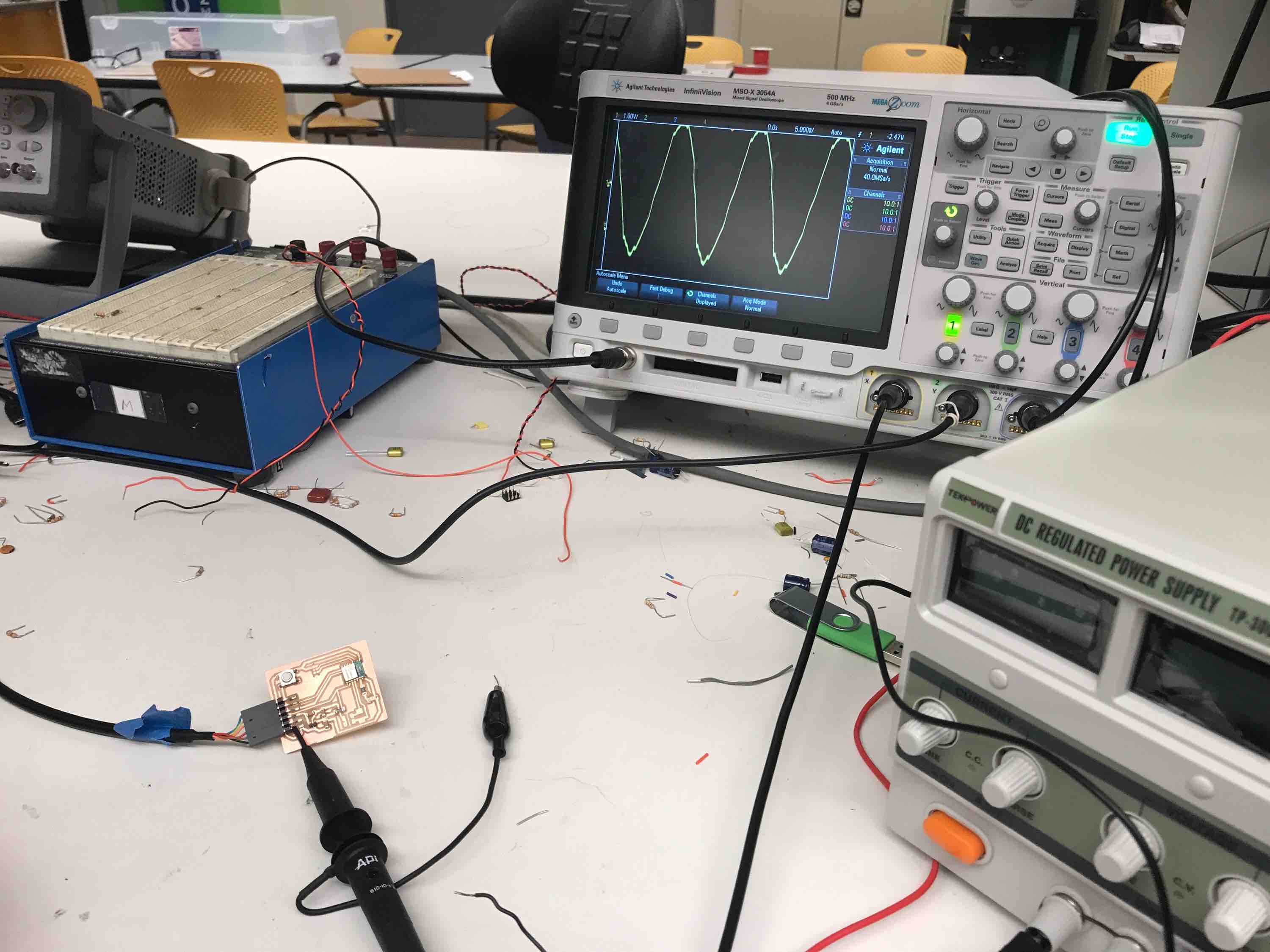
However, we never got a BLE signal. In fact, the code stopped before the Bluefruit portion so we suspect that the Bluefruit library may not be compatible with the BC832. We tried to use an oscilloscope to see if we could detect any changes on the RX/TX pins before it stopped working, but we didn't find anything useful.
I'm fairly confident that I can get this chip to work with BLE for my final project with a bit of debugging. One issue that I'm currently having is that I seem to be unable to program the board on my computer via a USB-C to USB adapter connected to a USB/FTDI cable. Since I don't want to be restricted by using only lab computers, I will do some more digging to see how I can fix this.