Week 6: Computer Controlled Machining
Designing Something Big
I wanted to make something I could use, so I ended up deciding to make a winter coat rack/hat rack for my room. I first drew out the design that I wanted on paper (I was going for a classy looking stand), as below:
But after some helpful feedback from my peers, who said that the stand may topple if a heavy jacket was only hung up on one knob, I changed my sketch to curve out near the bottom. This way, the center of mass of the stand would be consistently within the size of the structure:
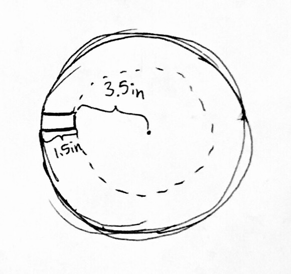
It was a bit difficult to CAD the curves that I wanted, so I had to first plan out the splines and dimensions of all the structures. I approximated the spline shape for the vertical components and calculated the dimensions of the center support discs based on the spline. I estimated that the slits would need to be 7/16inch wide (the thickness of the piece of wood) and that I would want the press fit to go into the piece around 1.5inches.
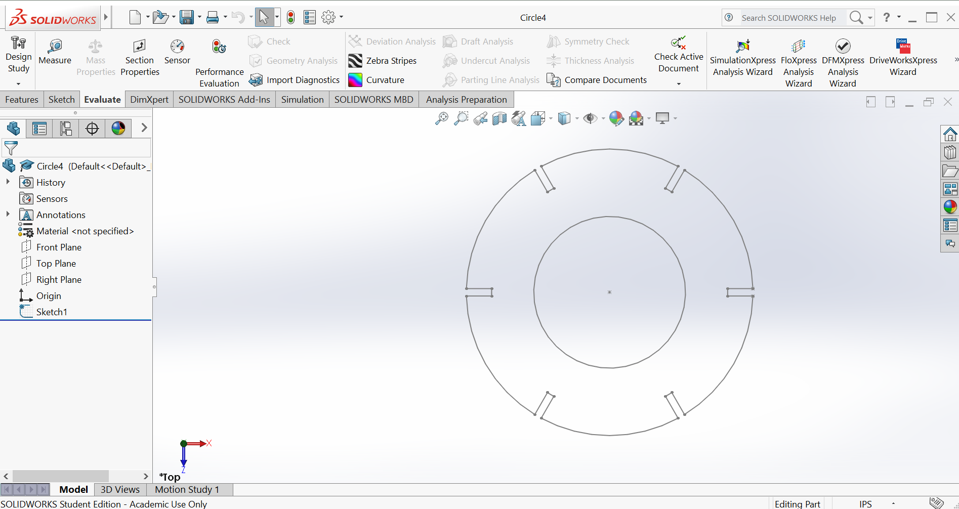
I used SolidWorks to CAD the shapes. The vertical curved spline was very difficult to make - I had to draw several circles for approximation and ended up freehanding a bit of it. The slits were also a bit tedious to add to the spline, because I needed to create a center axis/point of reference from which to make the slits. The circles were pretty easy to CAD, especially since SolidWorks has nice copy-paste and parametric scaling functionality. I decided to make 6 slits in my circles because I thought it would be more stable and more useful to have six vertical bars going up instead of 3 (the minimum). Shown below are the CAD drawings of my vertical piece and one of my center support circles:

Milling and Assembly
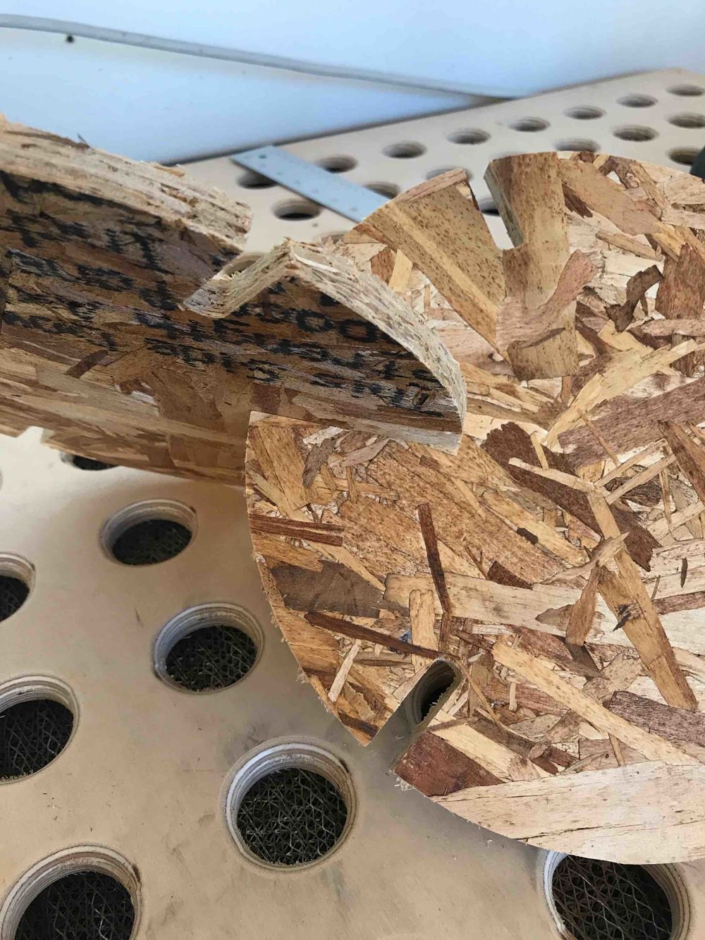
We first cut two test pieces to see if the clearance I gave for my press fit joints was sufficient. I just used one of the smallest support circles from my design and printed two of them. The press fit was fine but a bit tight. I decided that I didn't need to change my design since I could just smooth out my pieces with a rasper or sandpaper later.
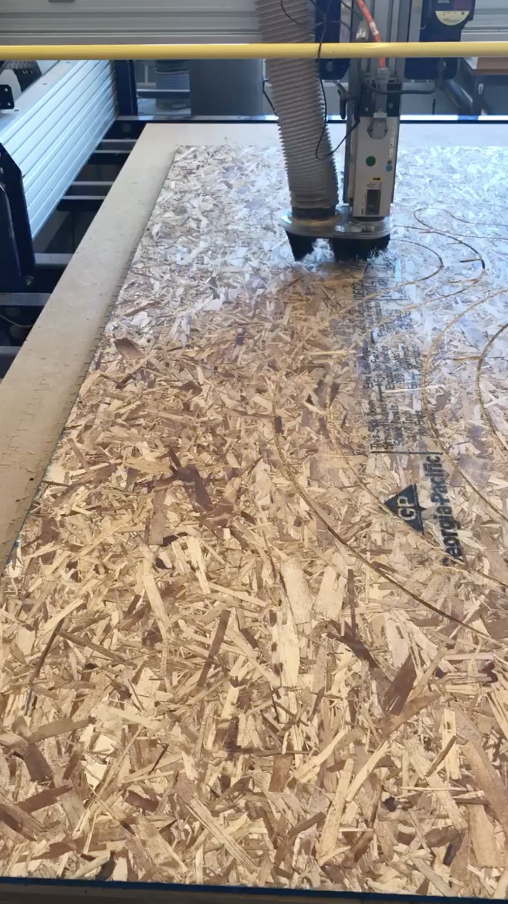
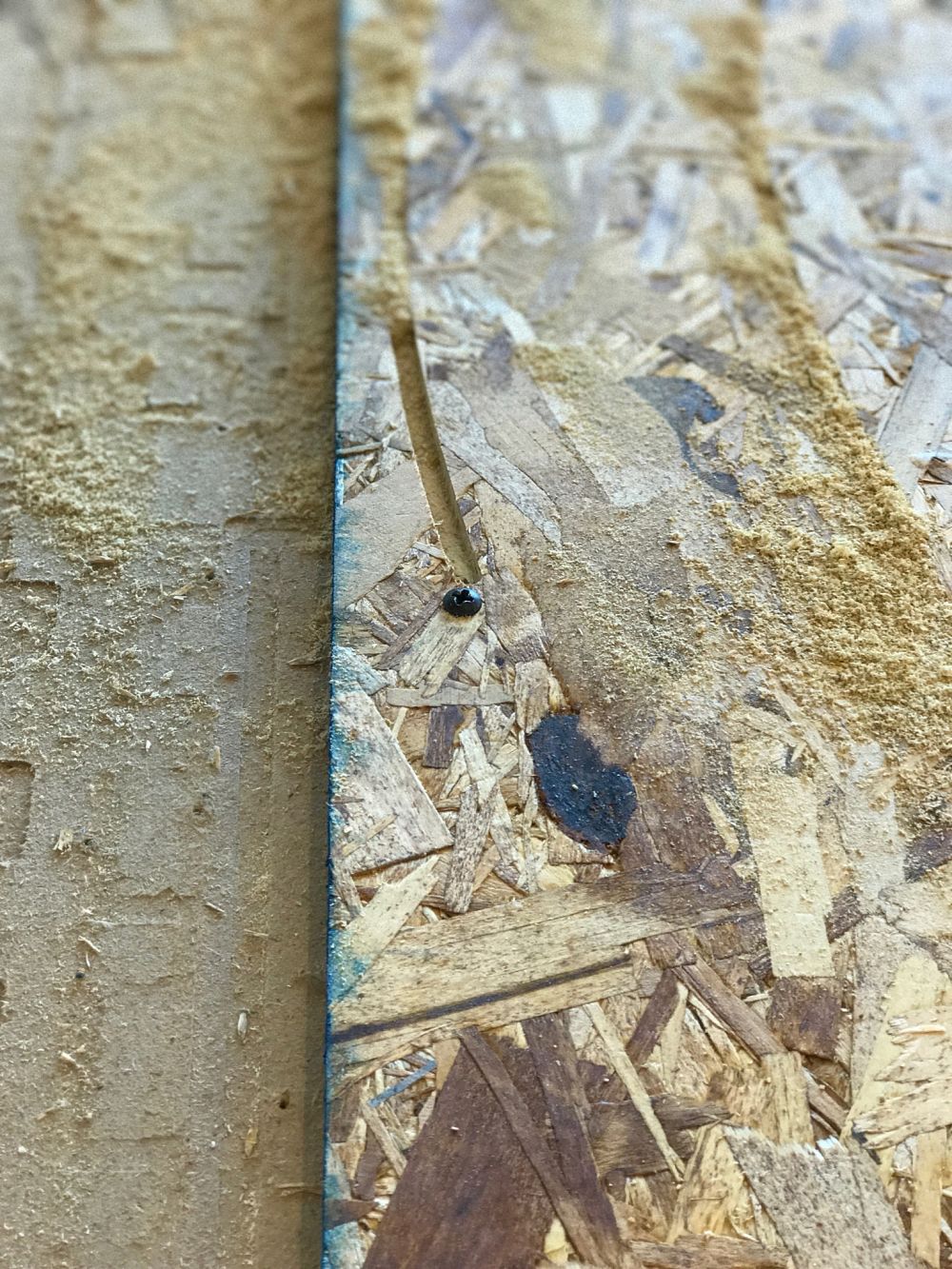
We then started to cut the large pieces. Possibly due to some miscalibration or some margin of error in the machine, we almost hit one of the screws holding the sheet of wood to the sacrificial layer. We had to hit the reset button before it ran over to restart the job.
You could say that we almost "screwed up" :)))))
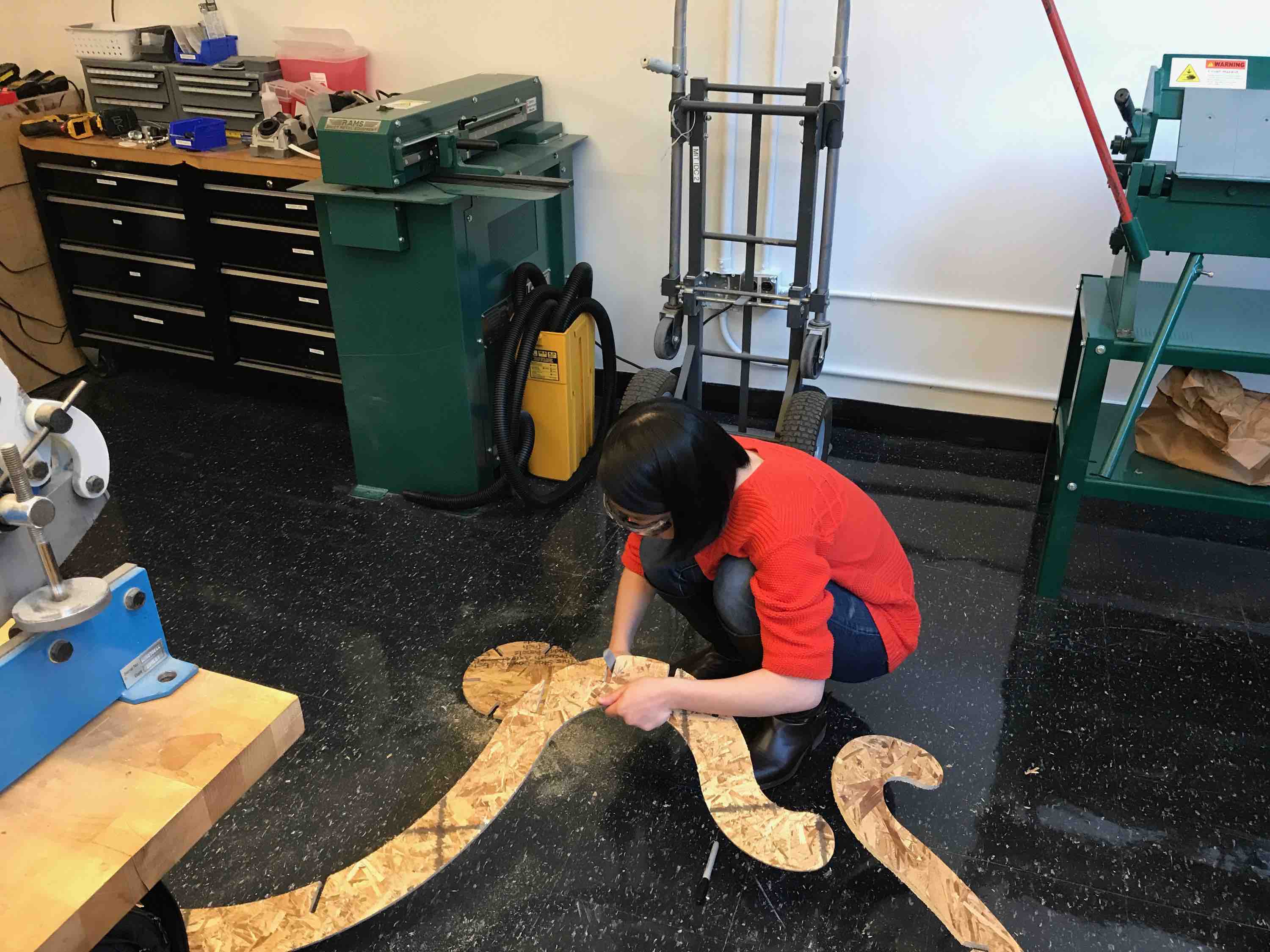
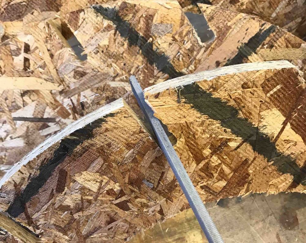
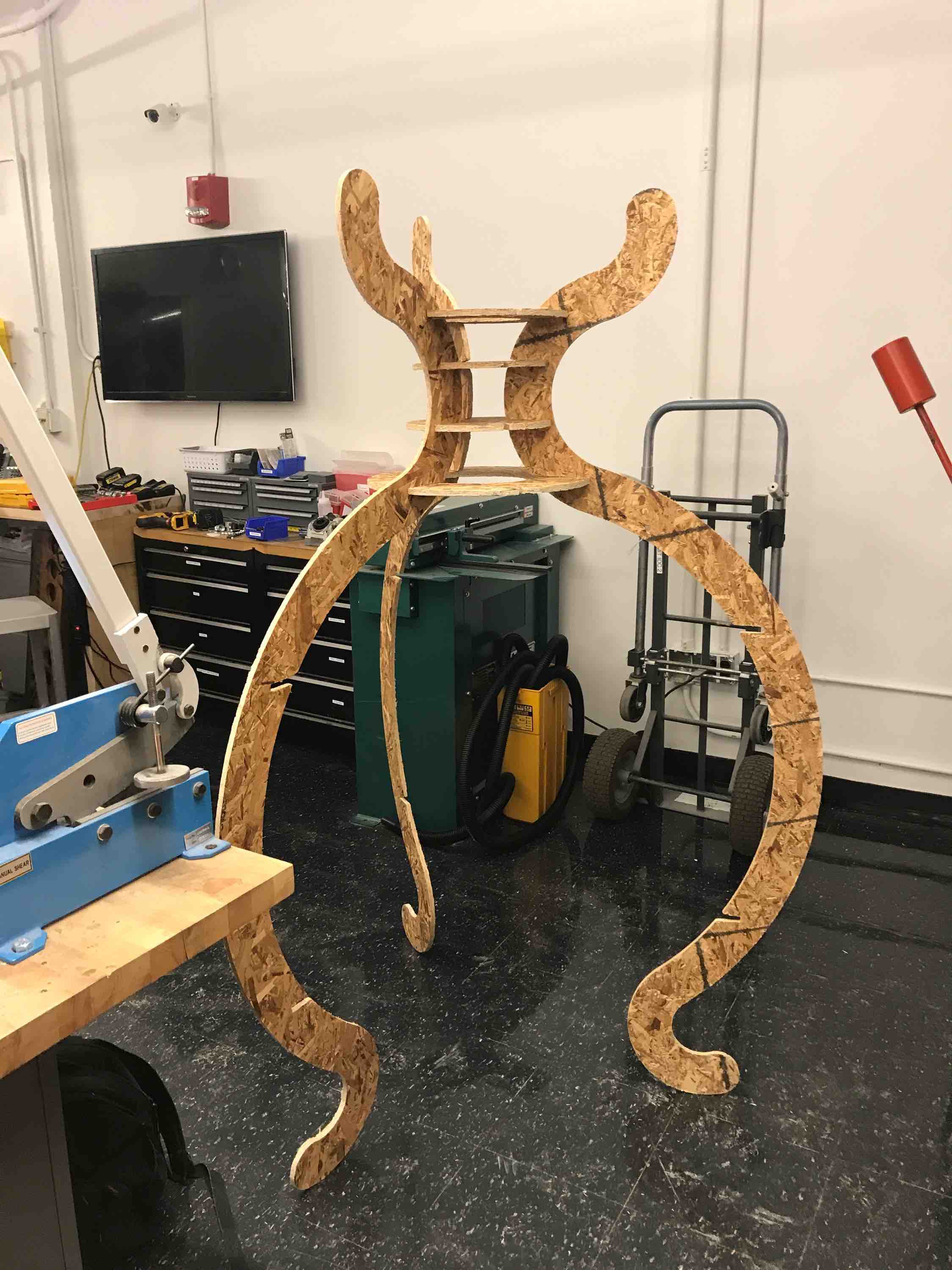
I ended up only having time to cut 3 of the 6 vertical splines - I didn't realize that the machining itself would be such a time sink. Ben and I fully used our 3 hours and I took an additional 45 minutes. The setup (securing the sheet with screws and calibrating the sometimes-finicky software+machine) and the cleanup (unscrewing the sheet and vaccuuming everything) was surprisingly time intensive. This resulted in 3 splines (which is sufficient to create a balanced piece with my original design) and 6 center support circles. Assembling this all together also proved to be a big challenge. I had to file away a lot of the slits because although individual joints could press together tightly, when I had to attach an entire column of joints at the same time (adding a spline to a preset circle), more space was needed to wiggle everything into place.
Here is the first spline that I put in (I started from the smaller circles and worked out the the larger circles):
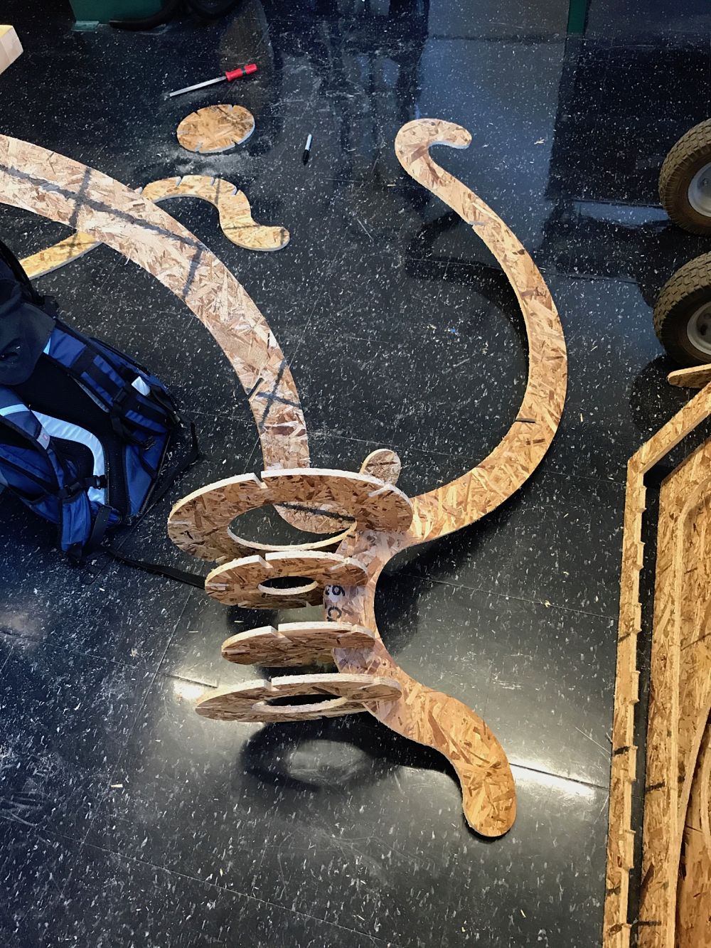
I then added all of the splines to the current set of circles. I wanted to add the biggest two circles last because I thought it would be too unwieldly to attach everything at once with such a bottom-heavy structure. This eventually proved to be a good idea. The structure was relatively stable with only the top supporting circles:
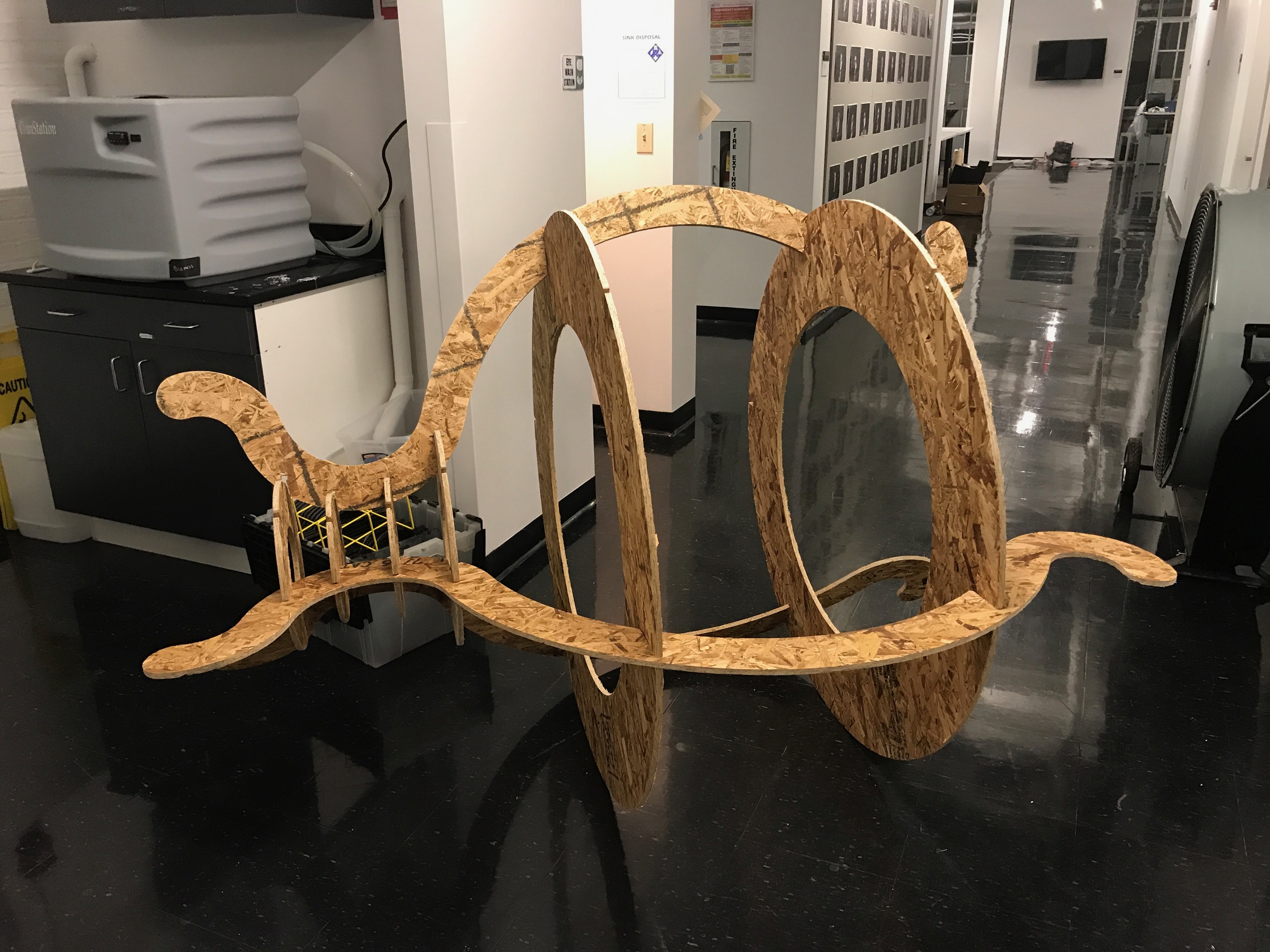
Here is the final assembly on its side (reading for transportation!). It was extremely stable from the top orientation with very little twist.
Transportation
Carrying my structure home was very difficult due to its bulky size. Since it was difficult to assemble (I had to use a mallet and got several splinters and cuts), I wanted to transport it home in one piece instead of taken apart. Special thanks to Gavin for helping me roll it to the freight elevator and down the stairs of the MIT Museum. Also, another special thanks to Ben for helping me get it through the doors of Sidney Pacific and up the elevators. Here is a fun video of how I transported it home down the road: