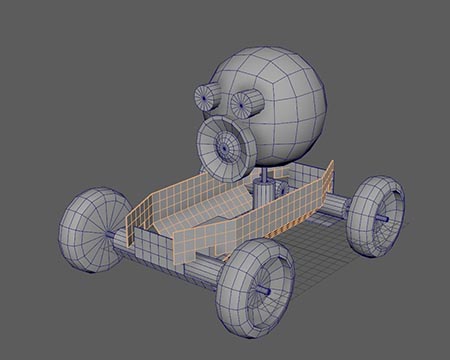
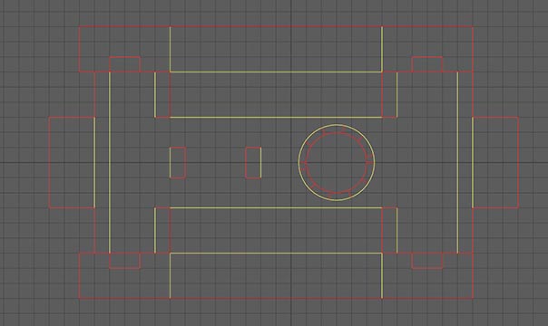
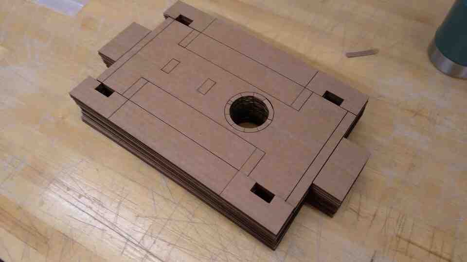
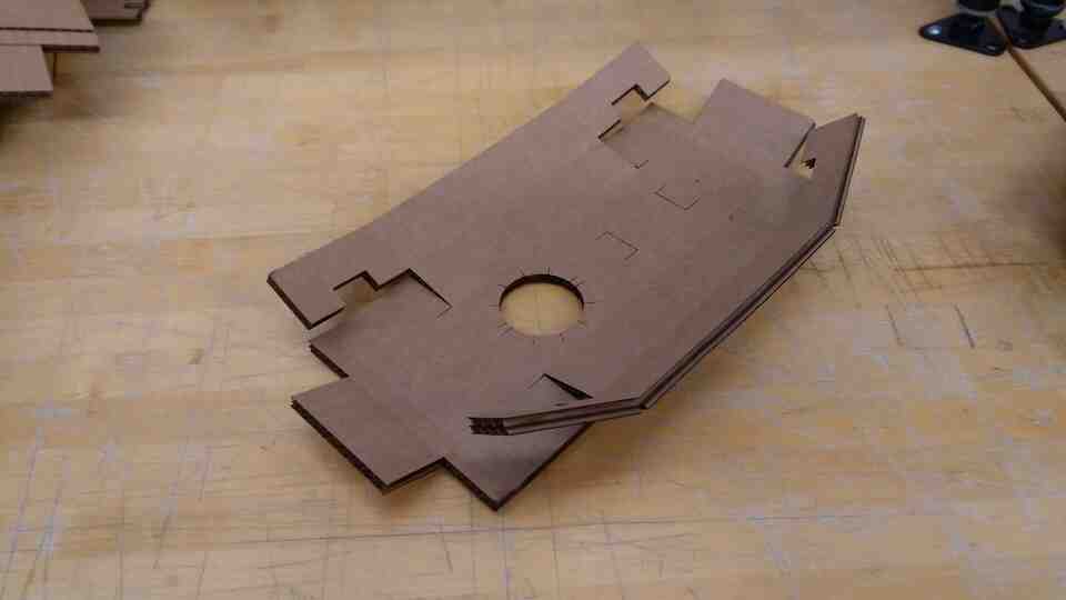
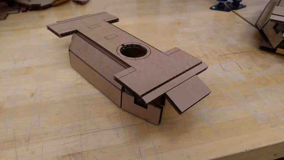
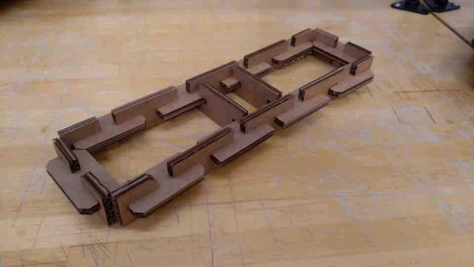
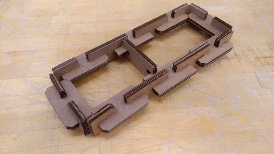
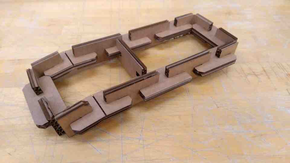
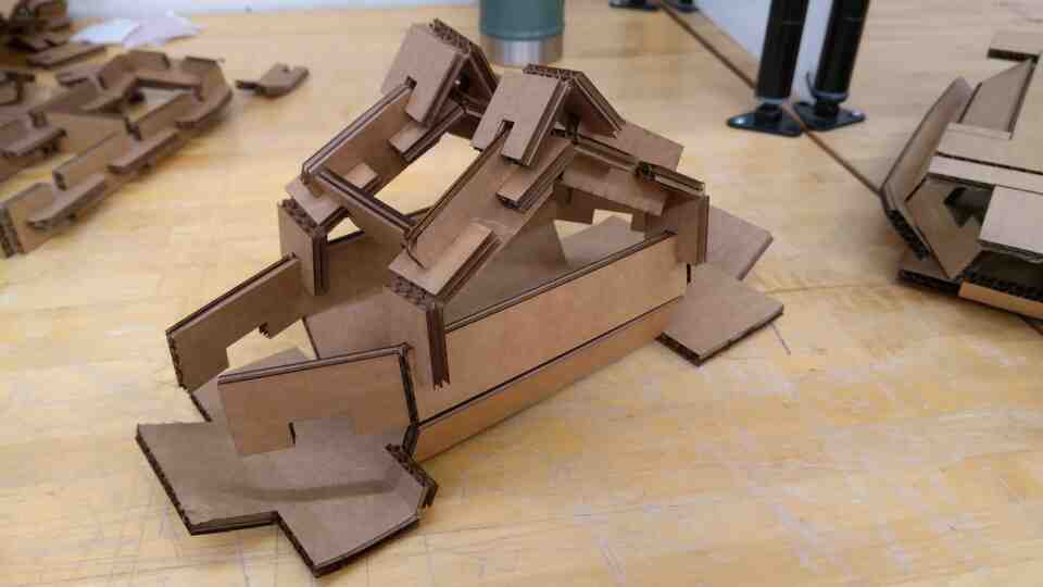
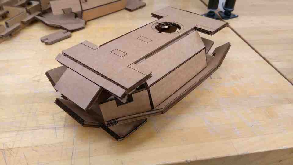
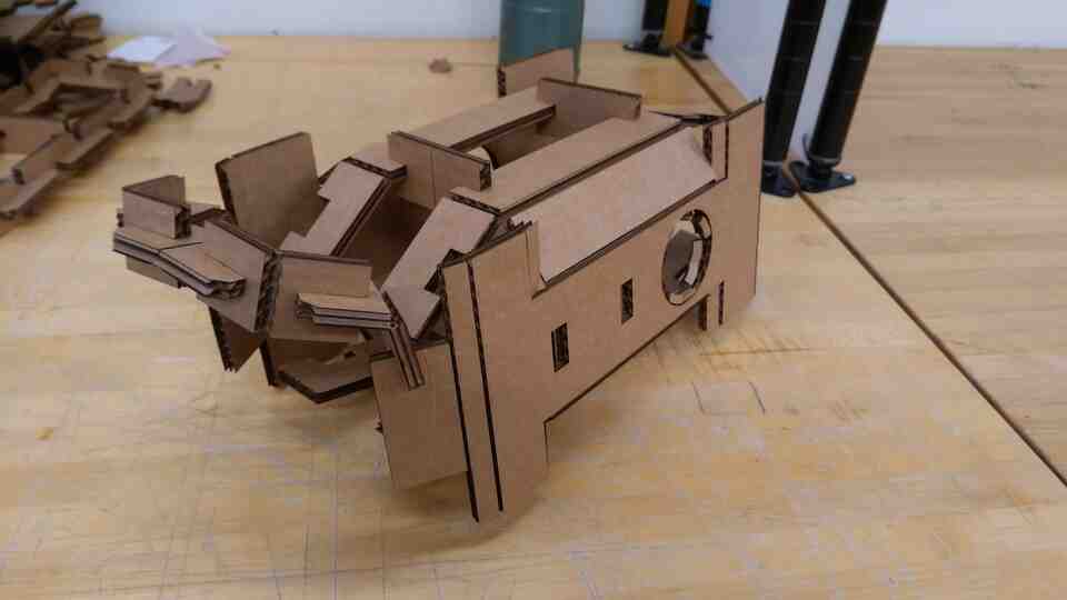
Using the laser cutter, I created the folding chassis prototypes out of cardboard, and played around with my press fit kit from week 1. During laser cutting, I noticed some overlapping lines, which almost became a fire hazard. I figured out that the when the 3d model is unfolded, some lines overlap.
I also combined kit parts with the folding prototypes for some design exploration.
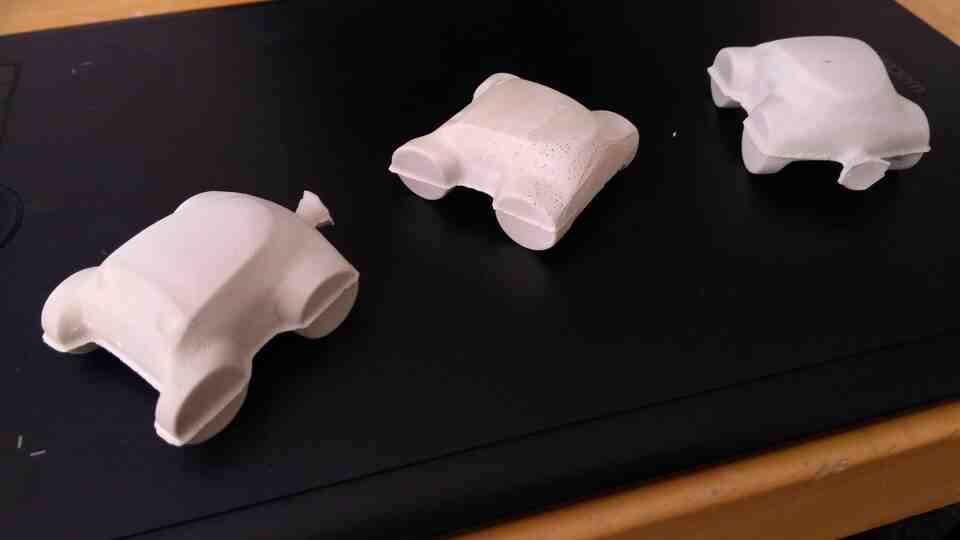
After the ideation phase of molding & casting week, I decided to make the rover smaller for added cuteness, and easier production to (maybe) make more than a single one.
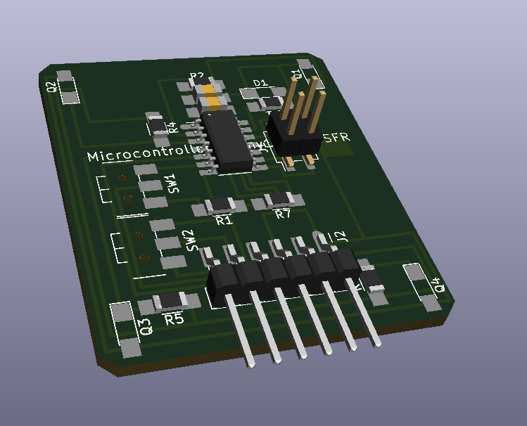
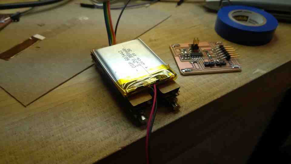
AVR based board design, and working prototypes that have a photoresistor and can communicate through serial.
I still need:
A board design with photoresistors on four corners.
Software to calculate a vector from the voltage difference between four sensors
Software to convert the vector to a two channel signal to drive the wheels (similar to how a tank steers)
A modular board setup that may integrate motors, drivers, and sensors.
What works:
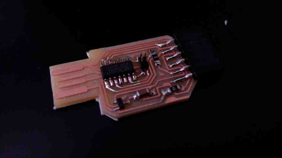
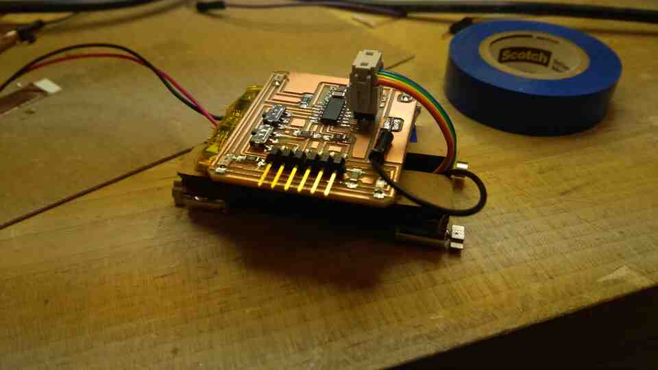
The FTDI to USB cable based on DS_FT232R works flawlessly so far for programming and communicating with my boards based on ATTiny412.
Photoresistors provide analog signal with far greater precision than I would expect
ATTiny is far easier to design and produce around than SAMD11c
What does not work:
My SAMD11c based serial programmer can program AVR boards, but can not communicate with them. I understand that the board design is physically capable, with TX and RX running through the six pin serial conector, but I am having trouble with the software. The bootloader that I am using are binary files which I can not modify. I located a .ino sketch which does not compile due to an error ("'Serial2' was not declared in this scope").
ARM based designs with USB input are more tedious to design, with connections to USB and the programming connector, require shimming all the time, and are slower and less efficient to load sketches on (due to the need for a bootloader). But they do work.
Questions to resolve:
How do I make/program a D11c serial programmer that can program and communicate with AVR based PCB's?
How do I connect motors to my board? What size motors, boards, batteries, peripherals do I need?
How do I upgrade the system to one with ESP32CAM's if I want to use a more sophisticated, computer vision based sensing moethod? Can I have a modular design where I can add/remove the ESP32?
What happens when:
Board design with four sensors, in the following week
I resolve motors, batteries in the output week
I get my serial programmer to communicate for independence from a cable adapter that I can not make myself. This is not urgent, but I want to be able use my own programmer
A new design iteration based on motor, wheel, battery, peripheral size, after sorting out motors
What I learned:
Soldering joints
How to design, fabricate, and program AVR's and ARM's
Creating programmers for AVR's and ARM's
Testing my boards with blink, button, and echo setups
Using molds to rapidly create multiple physical parts with materials that I can not 3d print conveniently
Laser cutting modular pieces for physical design exploration
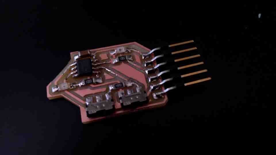
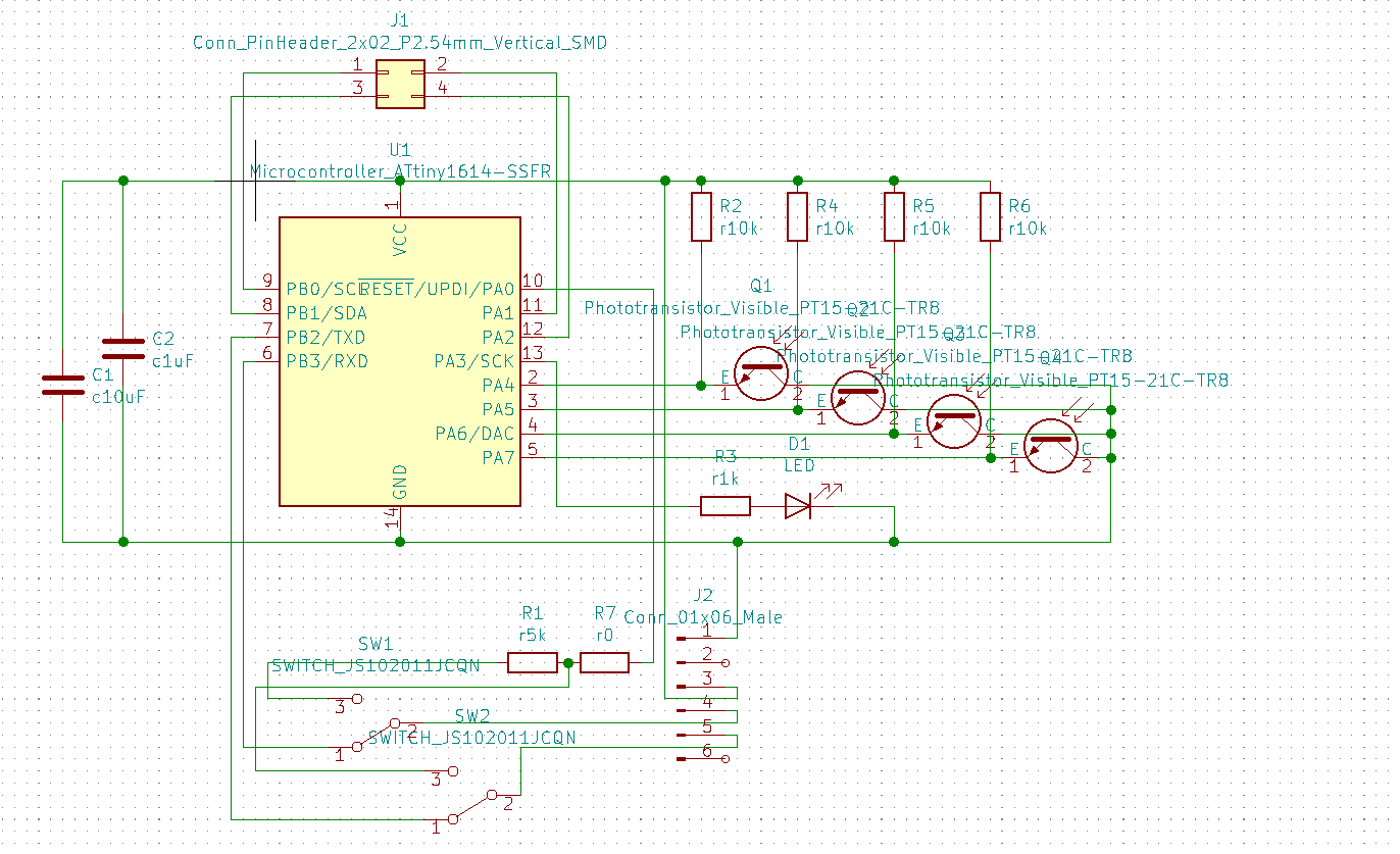
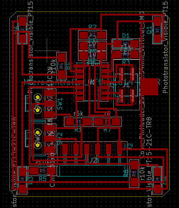
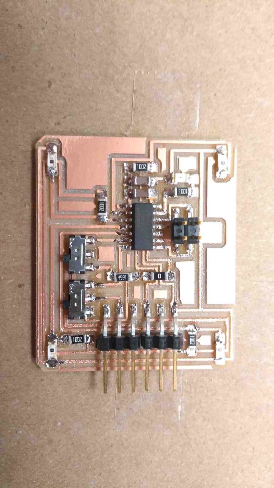
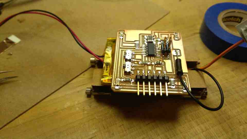
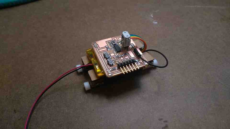
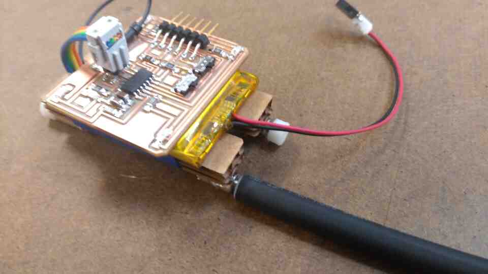
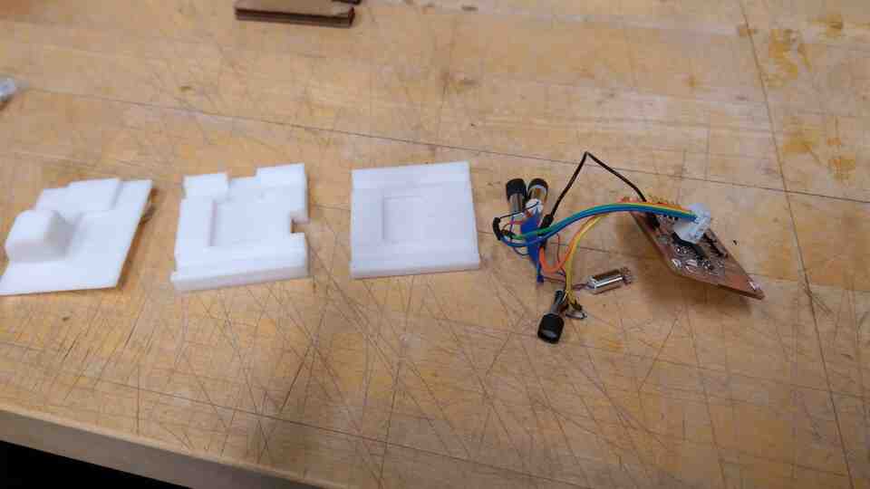
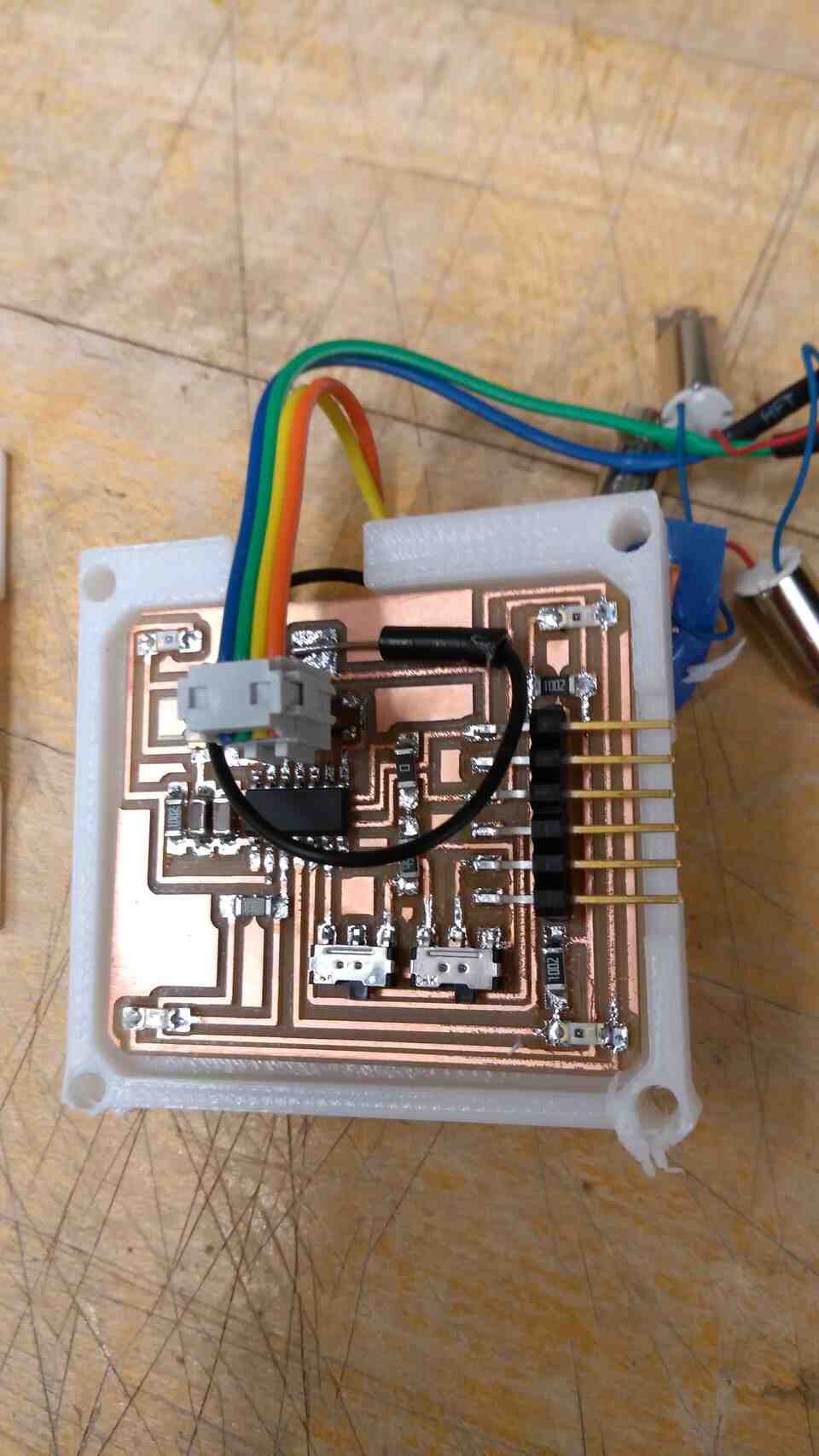
This week, I built a prototype with 4 phototransistors, 4 vibromotors, an FTDI serial connection and an LED, around an ATTiny1614.
I placed transistors on the corners, creating a 2x2 grid for light readings.
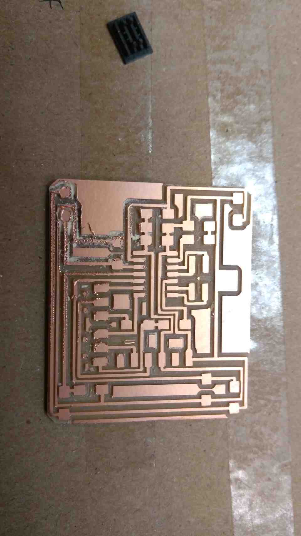
My first milling attempt was a little rough towards one side due to poor adhesion, yet it was functional after a light pass with sandpaper. I decided to recycle the first attempt as a platform to solder vibro motors, and build a new board just to be safe.
I wrote a basic software for the board, that reads analogue signals from each sensor, multiplies it by a value, and sends it as an analog/pwm signal to the corresponding vibromotor.
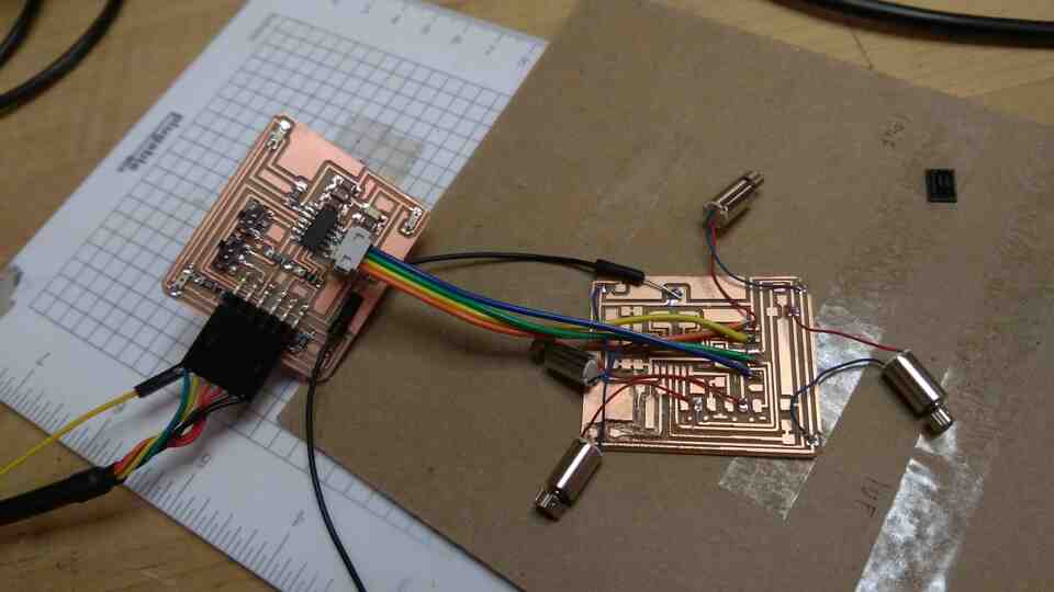
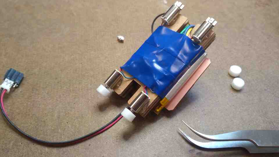
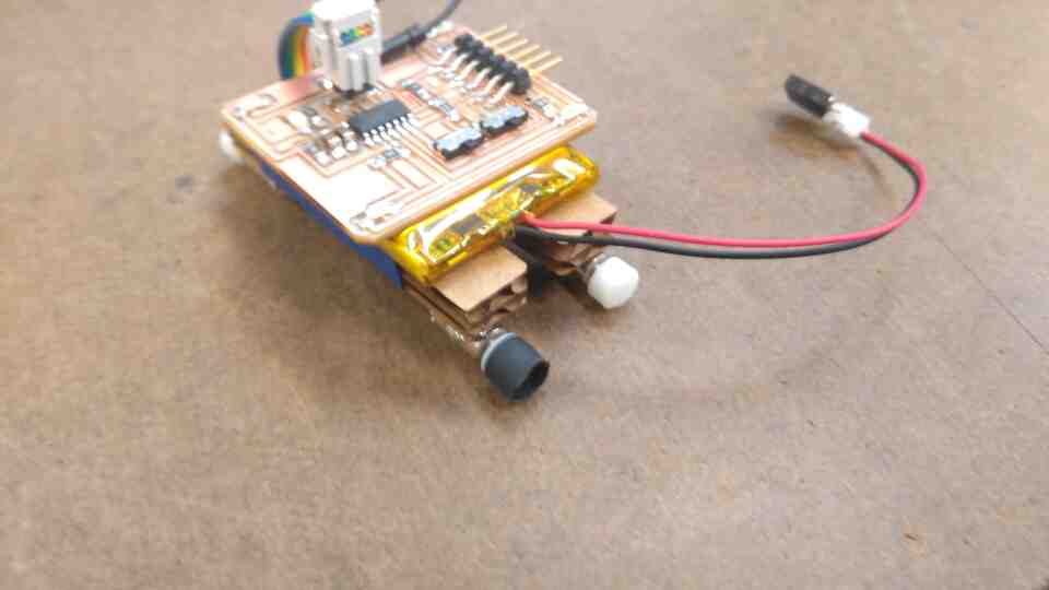
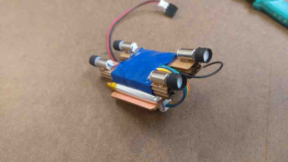
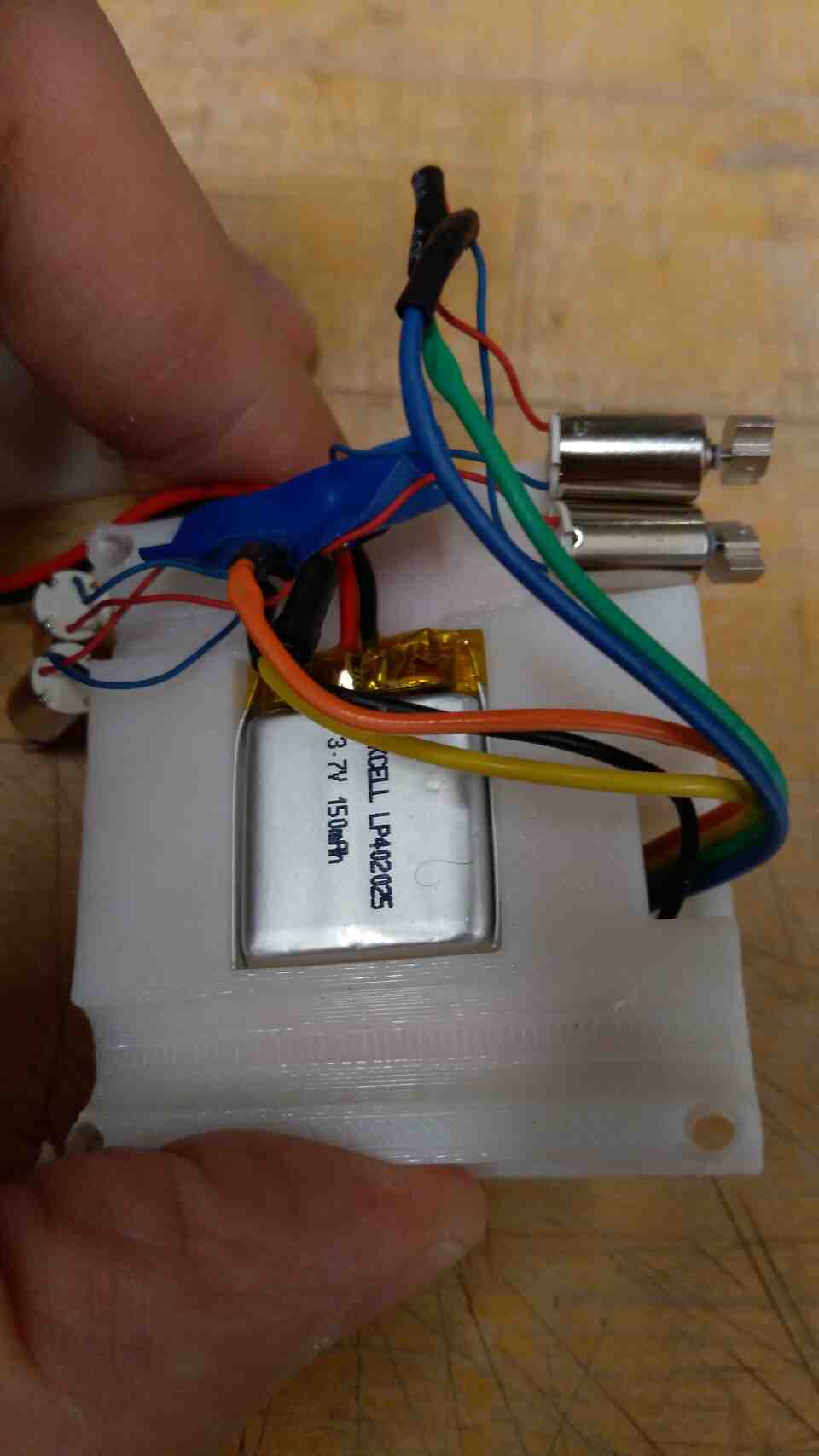
After a while vibromotors started ripping of the solder joints, so I constrained them.
I hot glued vibromotors to a cardboard chassis, and soldered their grounds to a piece of adhesive copper.
The rover does freak out in the dark, and somewhat seeks light. However, the code does not yet include the vector representation, and the rover ends up rotating right. I need to calibrate sensors in a balance state.
I replaced vibromotor weights with 3d printed wheels.
PLA did not have enough grip to move the rover. I used heat shrink tubing as tires.
Now the wheels either do burnouts, or stall. My conclusion is that the vibro motors have too little torque and too much speed.
A potential solution would be to hack servo motor gears. I decided to go back to vibromotors to conserve time.
Controlling direction on a vibrating robot turned out to be a challenge. After experimenting with code, different surfaces, and center of gravity for hours my cardboard chassis finally gave up.
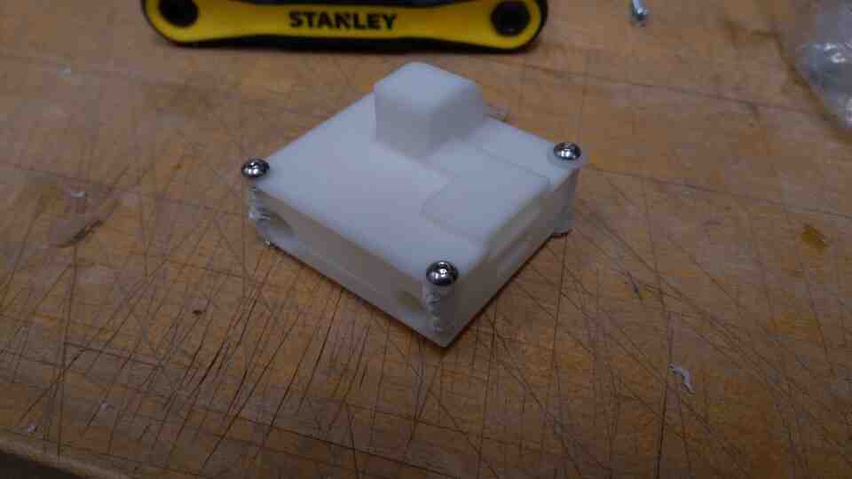
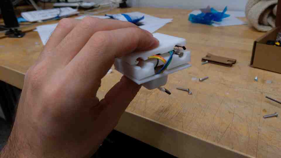
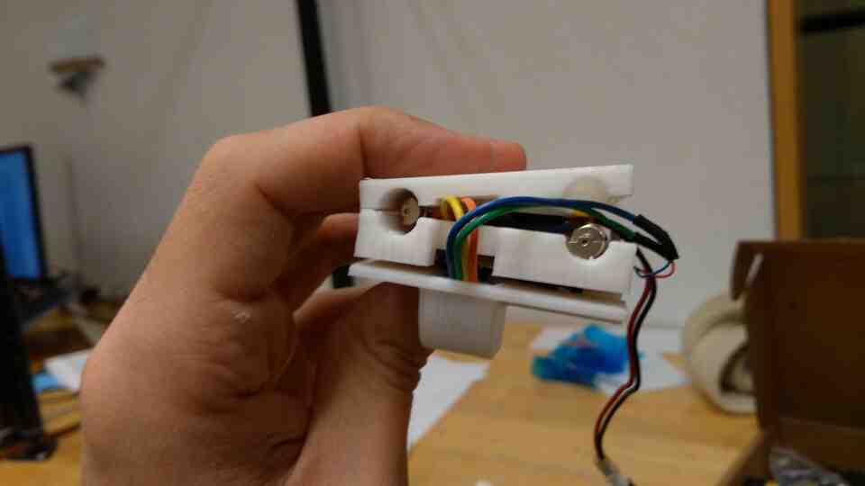
I designed, modeled, and 3d printed a three part body for added stability. The body is a square shape with phototransistors on each corner. I kept the bottom flat, in order to experiment with different designs for legs.
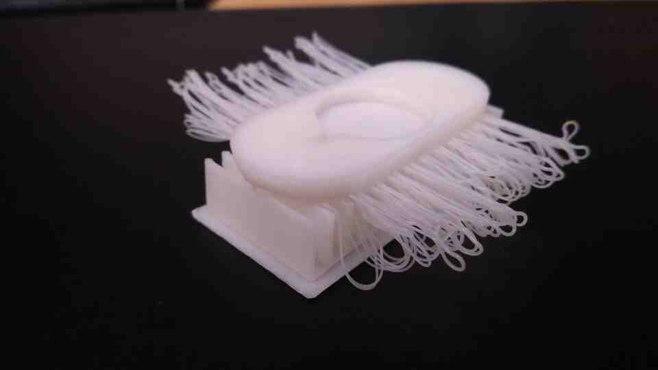
I also discovered bristle bots, which typically are simpler versions of my project with just a battery and one vibromotor connected to a tootbrush head. However, I discovered one video where two brushes are used like tank threads, wirelessly connected to a gamepad resulting in somewhat controllable movement.
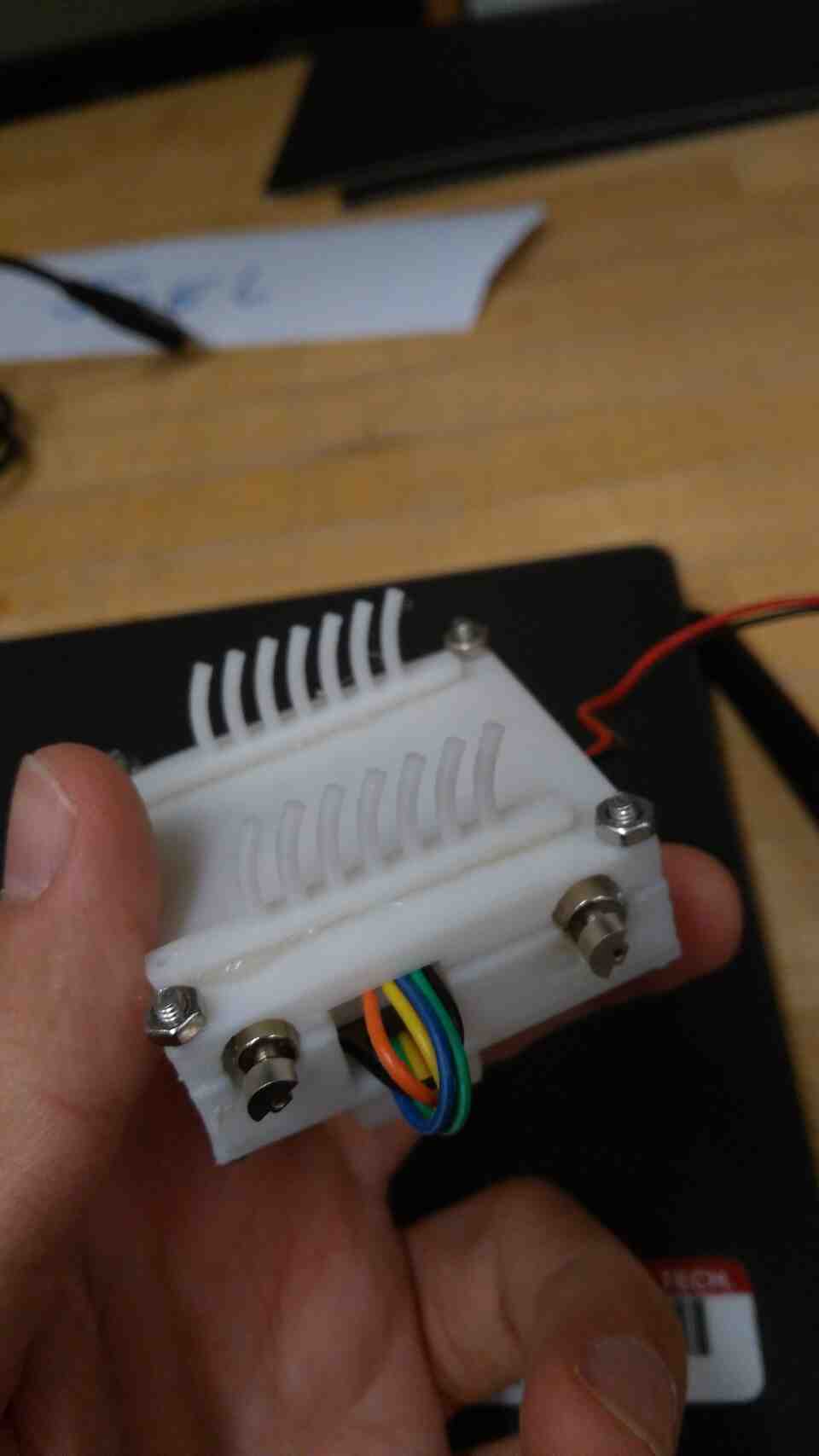
I tried different approaches for 3d printing legs of brushes, ending up modifying a design with curved legs that proved to be the most controllable.
By running vibromotors at different speeds (with PWM), and in different configurations, I can make the bot:
The combinations are quite unintuitive. Possibly because the center of gravity is in an awkward position, and there are performance differences among vibro motors.
I will update my code to include a state machine with different motor combinations for steering.
I need a function that takes 2 dimensional vectors which I acquire from signal difference among four phototransistors on each corner of the rover. The function should switch states based on thresholds in vector axes.
What I would prefer is a 'fuzzy' state machine, where to rover could be in between states for more organic motion (this happens a lot in character animation).
My current software has a primitive state machine that steers the rover based on lateral difference (vX) between the sensors.
Light intensity has an inverse relationship to power transmitted to vibromotors.
Result is a rover that steers towards light and calms down when under light, yet freaks out in darkness.
Next step is to utilize longtitudal light difference (vZ) to create a smarter mode of navigation.
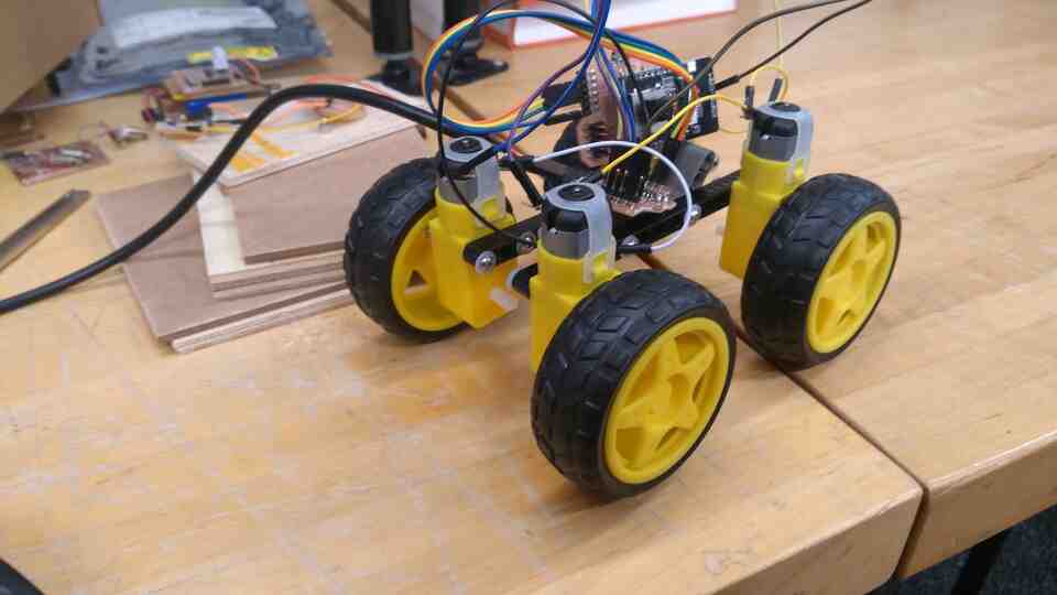
In parallel to the small vibromotor rover, I developed a larger one with geared DC motors.
One approach was to connect motors to a cardboard chassis with cables routed in the grooves. I had to abandon this idea temporarily due to material and time constraints.
Instead, I used LEGO parts and bolts to put together a variable stiffness development chassis.
Using my boards from networking week, I connected an ESP32 to my main ATTiny1614 board, which then connects directly to the motors. The motors are rated for 4.5 volts, however I can run them two at a time from a 3.5 Volt LiPo battery, and even 2 volts from a power supply. However, when I connect motors directly to the microcontroller, I get no movement.
Checking with the multimeter, I noticed no resistence between the ground and power pins on the motors.
I will return to this project on a later spiral. For the time being my focus is on completing and documenting the small version.