Week 5 - CNC Machining

Making something big!

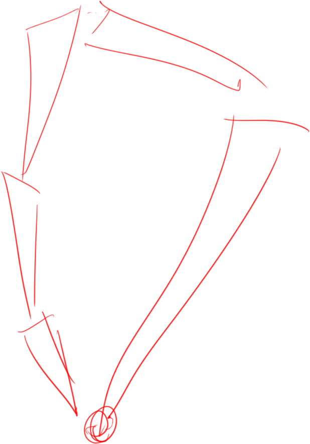
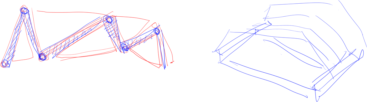
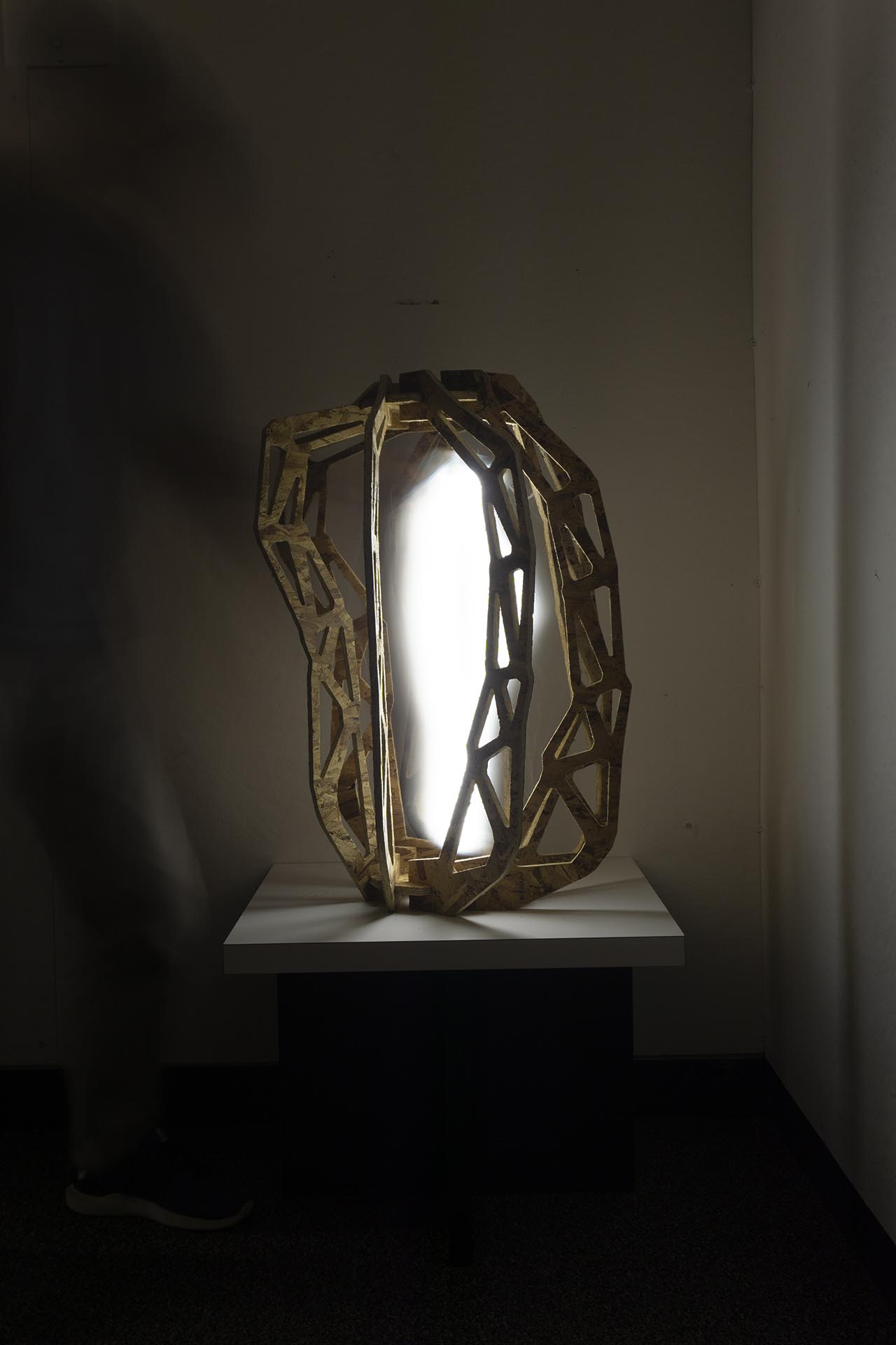
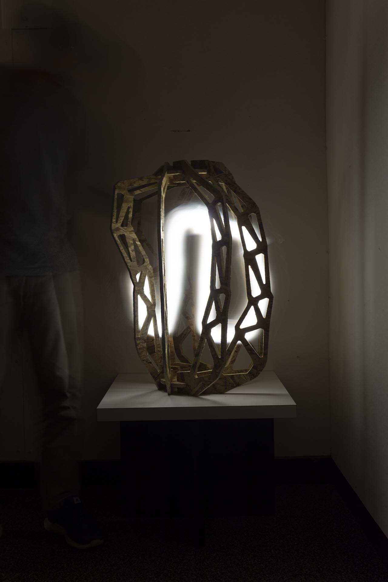
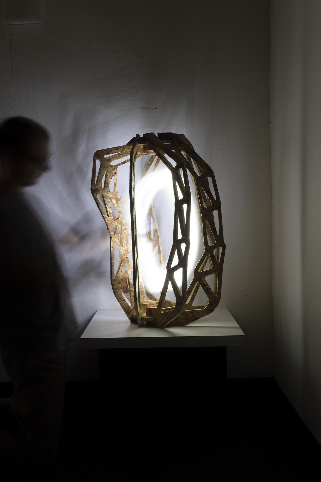
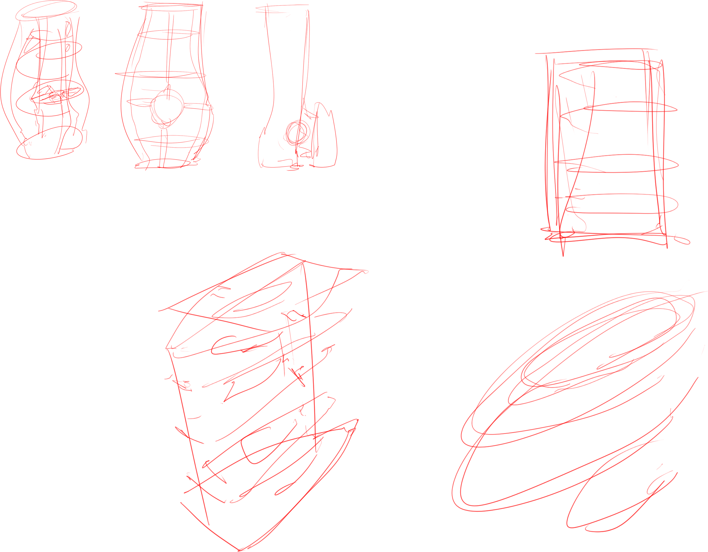
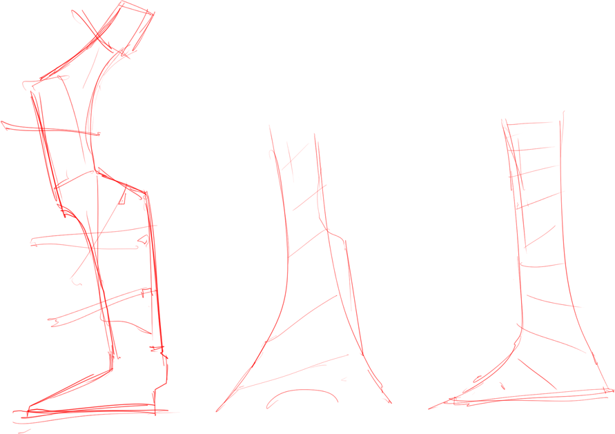
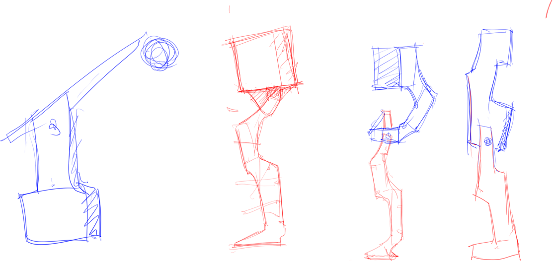
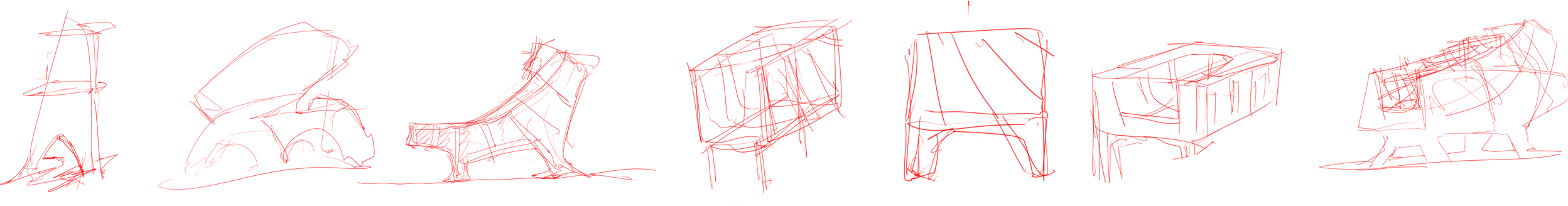
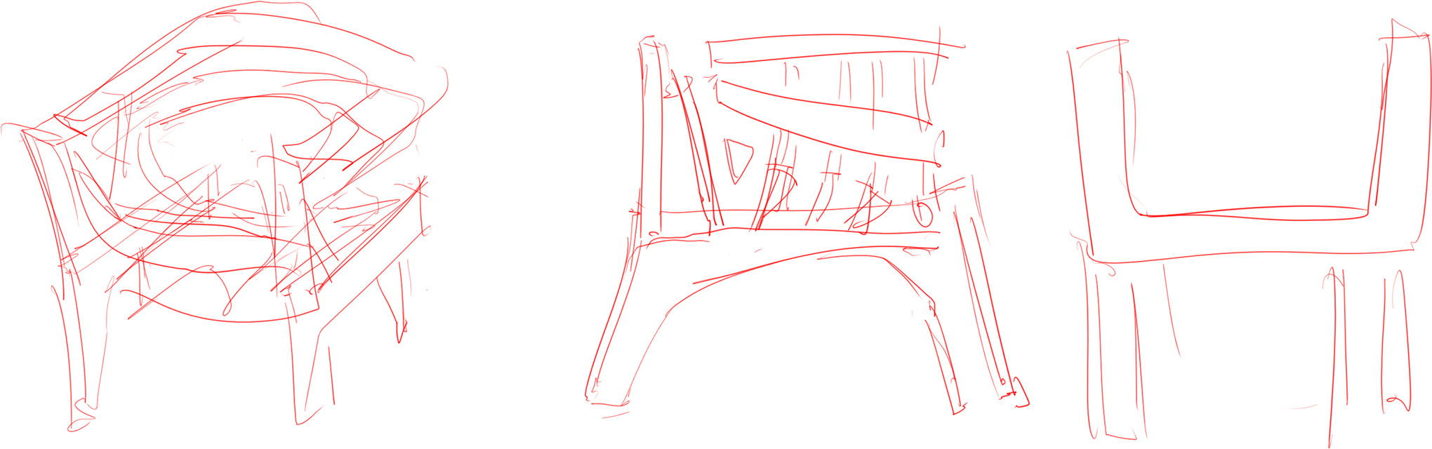
Since the assignment had no constraints other tha making a big thing, I started sketching freehand and 3d to explore some ideas

sketch sketch sketch sketch sketch sketch sketch sketch

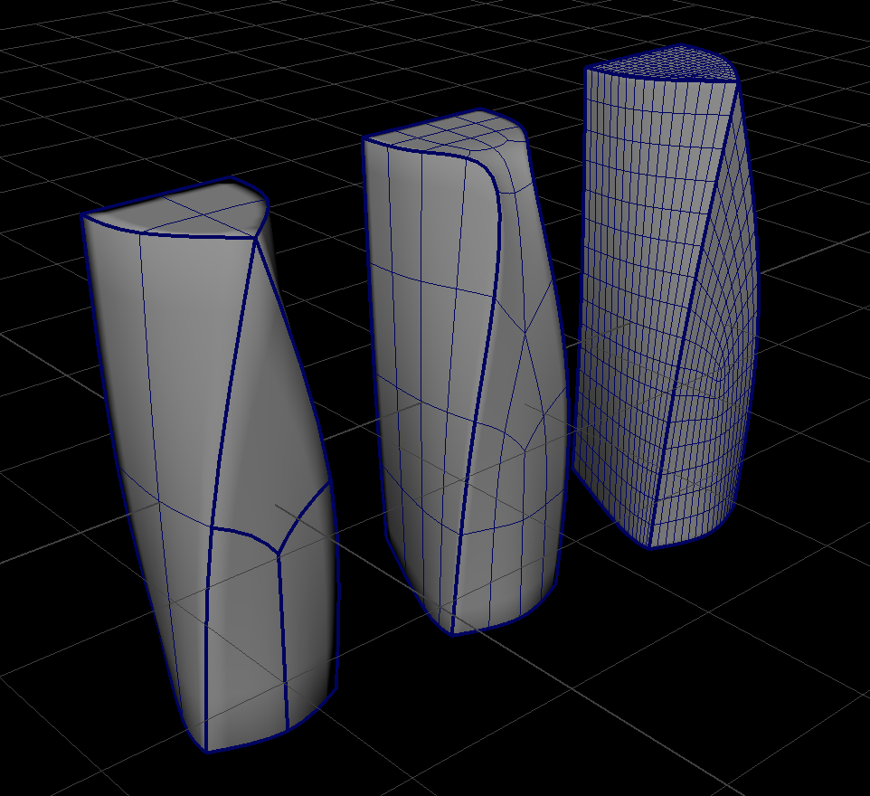
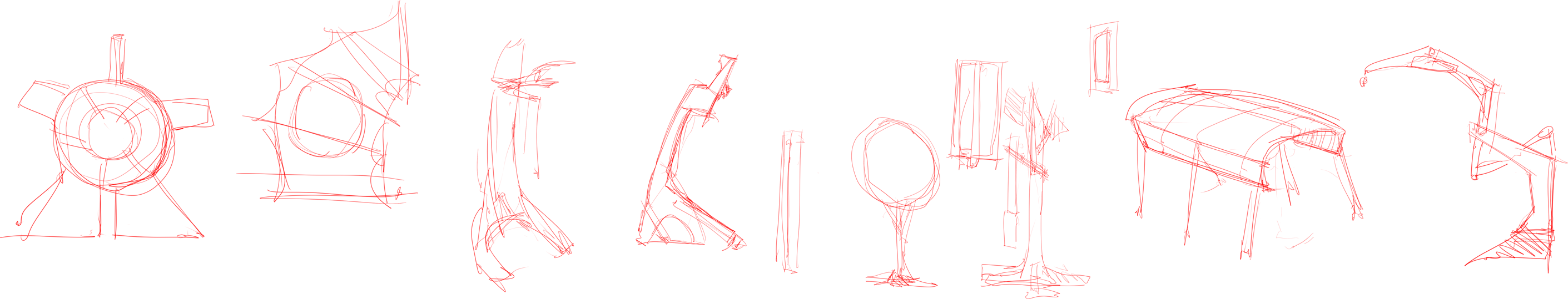
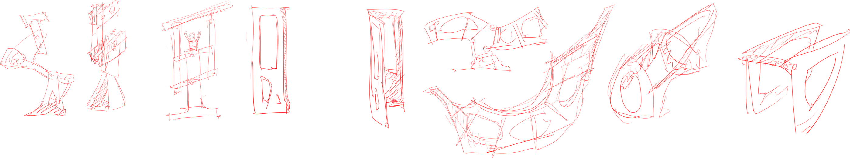
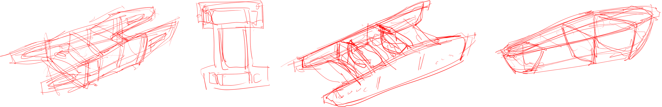
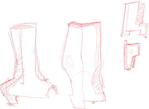
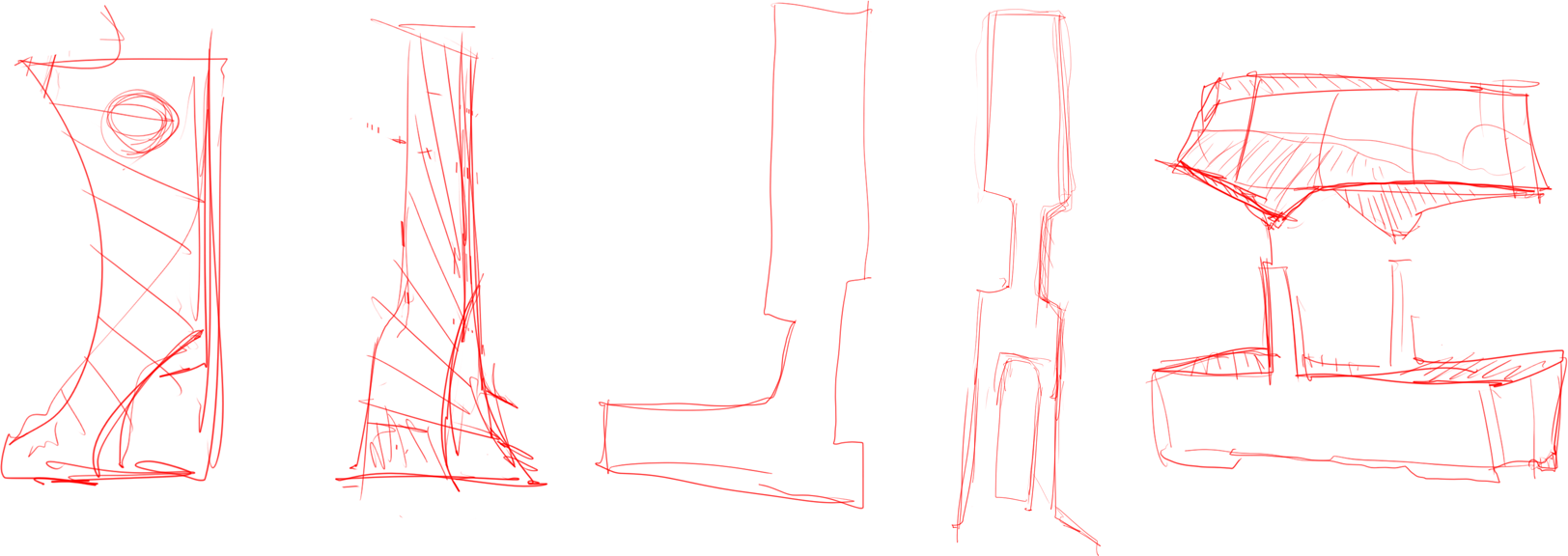
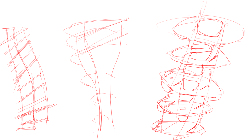
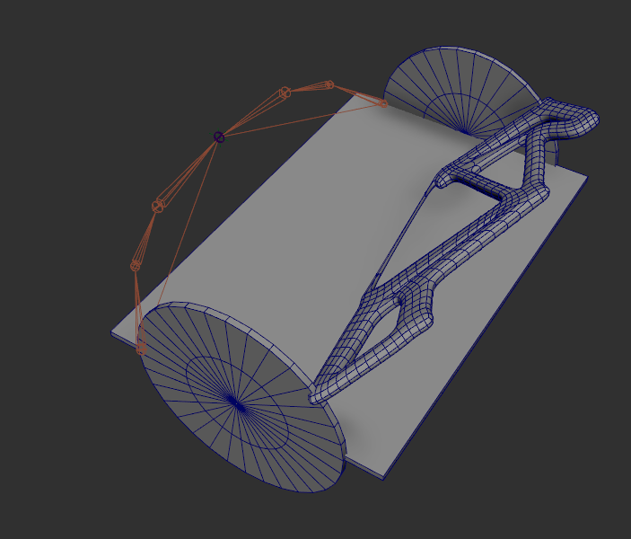
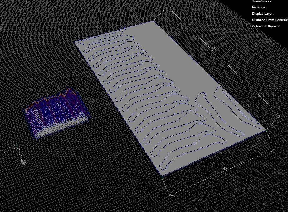
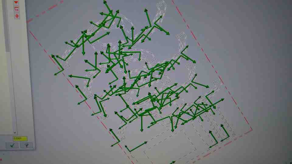
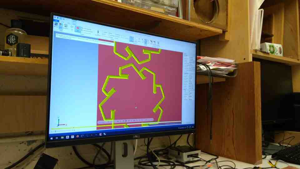
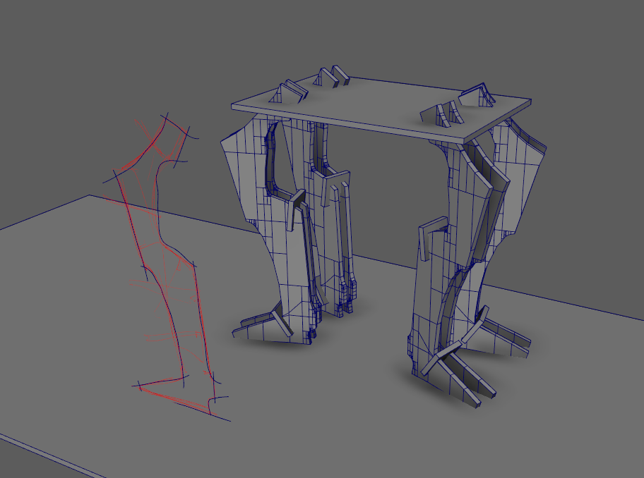
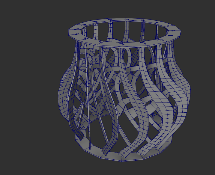
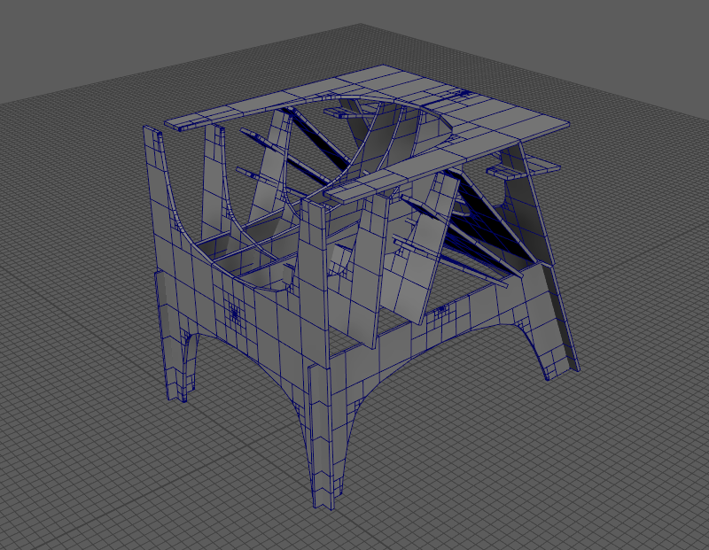
I meandered for a few hours in Maya, creating sculptural forms, a table with legs, some chair designs until I settled on a parametric chair.

sketch sketch table sketch sketch lamp table table table table sketch sketch

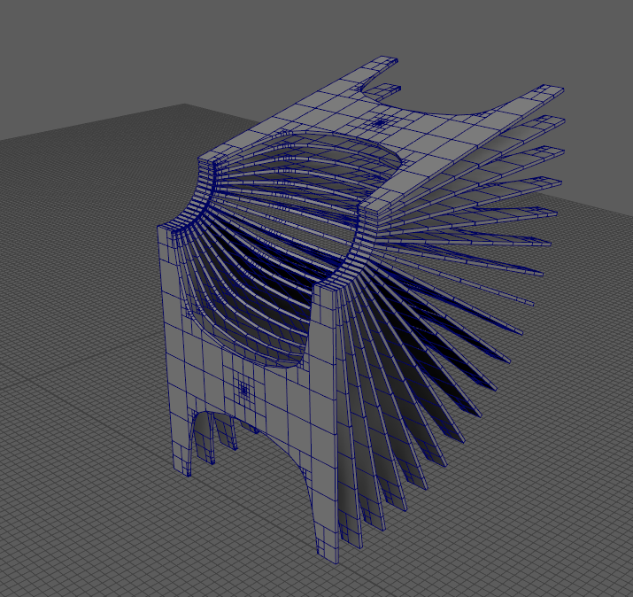
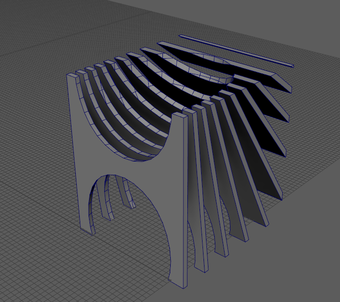
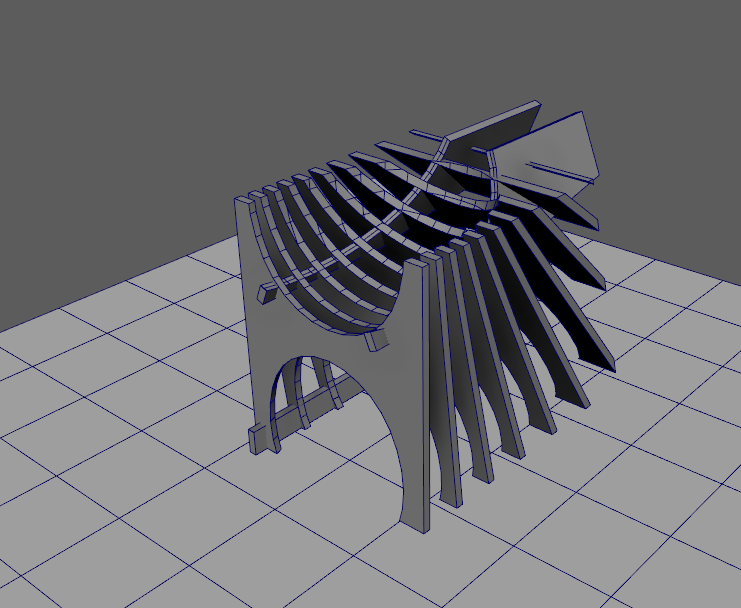
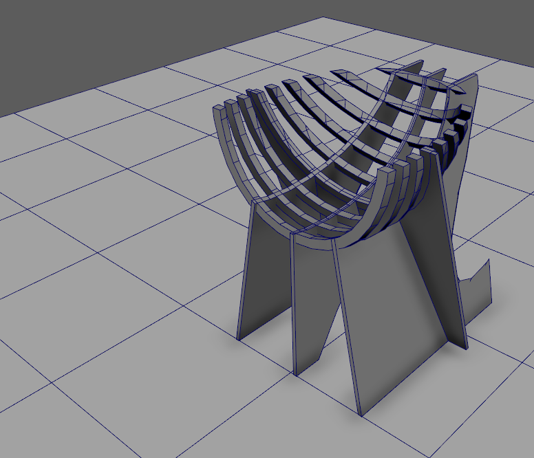
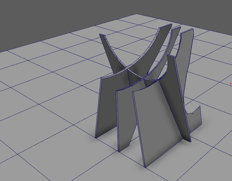
On the next day, after a few minutes in pinterest, I noticed that the internet was saturated with CNC chairs. I decided to investigate a different avenues.

sketch sketch

Based on these sketches, I decided to explore more abstract shapes by using inverse kinematics as a tool for generative design. I created to basic skeletons with a shared IK handle in the middle. Then I skinned the rigs to a truss structure.

  • Using the rigged geometry, it is relatively easy to generate instances where the relative position of the IK handle is defined as a parameter.ik
  • To have a smoother file transfer experience, I converted the IK rig to a 2 dimensional setup with NURBS geometry so that I can export 2D CAD files for CAM.
  • I started thinking about the fabrication constraints of a 4 by 8 foot board.
    stacking
  • Then I created a hacky parametric design through Maya's driven keys and timeline.

I made a laser cutter model to test the design before committing to CNC.

test test1

The next step was to create dog bones. I did this in Rhino.

dots

    Some key points:

  • Sheets must be flush at corners to ensure vacuum seal.
  • Outside cuts should go clockwise, while inner cuts are counter-clockwise.
  • Vacuum at all steps after cut to keep a clean workspace.
flush corner cutting vectors
vacuum

The remaining work is mostly filing.

break
file file1 file2 piece piece1 stack stack

Parts stacked nicely on the planar base. However, 0.5 inches was a bit too much for a snug fit. This finding is different from our group assignment, where 0.5 inches worked perfectly. At this point I assume that material thickness varies from sheet to sheet.

planar

The next day, I decided to go back to a circular design, both for a more sculptural form and as an excuse to try tighter fitting joints. I modeled a circular connector, with 0.48 inch slots.

circular circular

    some notes:

  • When using smaller sheet, vacuum can be preserved using plastic sheets on the empty areas.
  • If you forget to select, and cut circles, wing cutters are handy end effectors for creating them.
  • Wood glue is unavoidable under tight deadlines.
sheets wing cutters wing cutters

Here is the resulting sculpture! Might become a lamp someday.

assembly final

To experiment with potential uses as a lamp, I did some experiments with light painting. To do this I went to a dark room and set a 10 second exposure.

lightpaint lightpaint lightpaint lightpaint lightpaint lightpaint lightpaint lightpaint lightpaint lightpaint

And why not use a facemask as diffuser?

lightpaint lightpaint lightpaint

Special thanks to Ganit for helping with the photoshoot.

Results of our group assignment were mixed. While in the initial trials 0.49 inches resulted in snug fits, later test by MQ suggested 0.5 was better. In my project that was further down the material stack, 0.48 was even better.

group group group group group