My DC11 board with an LED and switch would only function when it was connected to the Atmel ICE programmer via the 2x5 pin connector. This week, it did not finction at all.
Upon closer inspection, I noticed that the solder joints for the button were a bit sketchy. Moreover, recalling an insight from Raghav, I found out that it is a better idea to bend the legs of the button out before soldering.
Upon resoldering the button, the board began to function through USB. The microcontroller already had a bootloader, and I managed to upload sample programs with the Arduino IDE.

The next issue was with the LED. I learned from Kim that I could use Arduino IDE's sample blink program to test my LED. The LED was connected to PA 04 on my microcontroller, although it did not respond.
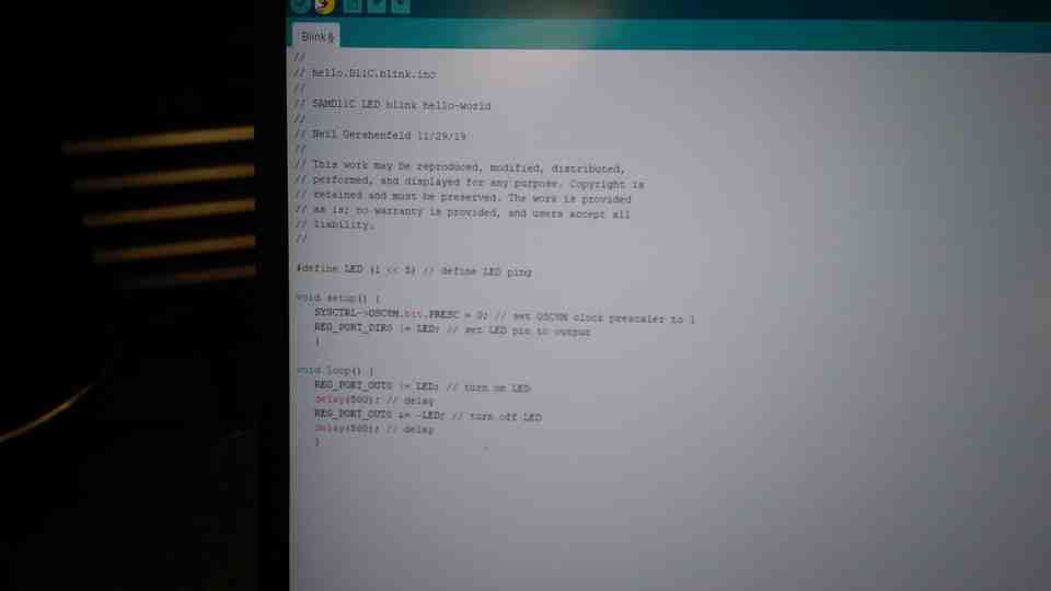
I tried to figure out Neil's sketch instead, and suspected issues with soldering. Just to be safe, I also connected the LED to PA 05 (same port as Neil's design) to no avail.
To check if the LED unit functioned, I used the power source in Archshops. Then I found out that there was a tiny gap in the copper trace near the resistor. Using the wire from PA 05, I soldered directly to the resistor, and now my board blinks!