Week 10- THE NEILBOT
I need to sleep


Of course go to Neilbot main page. for all the information. Here I just talk about my personal accomplishments and struggles and trauma and joy with the Neilbot and sleepless nights.
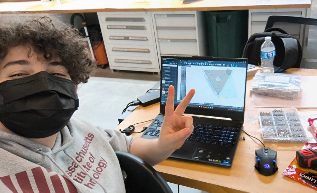
I took on the role of mechanical design expert for the Neilbot team. I decided to take on the structure design and leave the mechanism for the rest of the team. Was this foolish? Definitely. But I has the most CAD experience, and I could tell from the very beginning how crucial would the structure be for the success of the robot. So I designed the whole thing in Fusion 360, hoping to be done by friday.

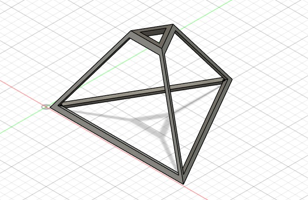
Of course that never happened lol. I had to iterate many times the design in many ways to figure out what we needed, taking into account what we needed inside and the dimensions outside. The first order of business was making a simple design for everyone to visualize.
As a team, we decided we would need two layers, an inner core for the elctronics and the mecanism to be attached, and the outer surface in which the faces would move in and out.
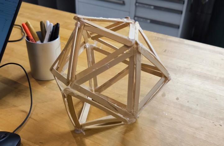
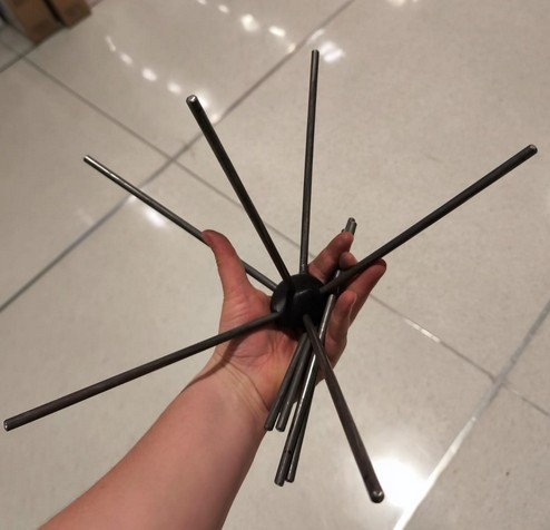
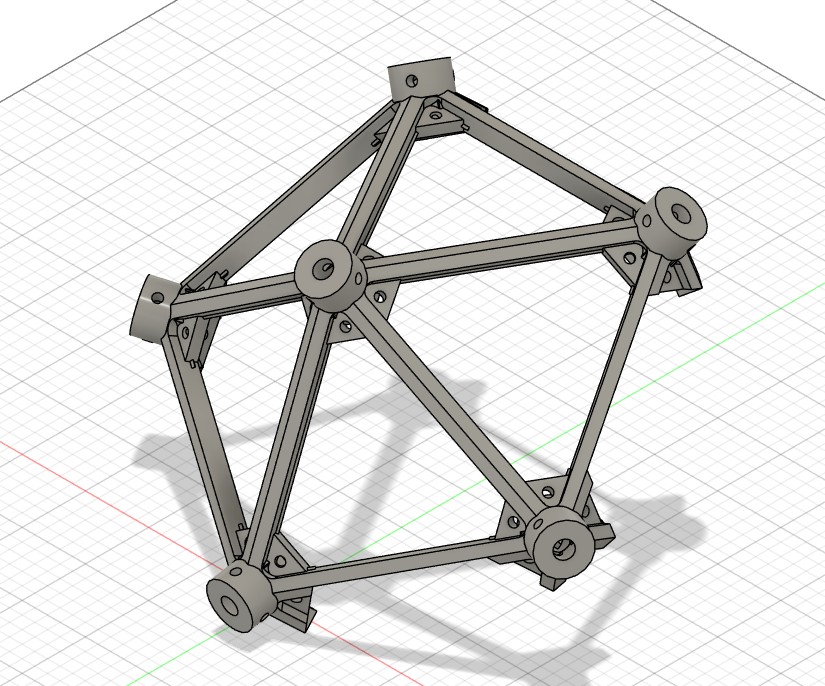
I pushed in the beginning to make a structure with all edges made out of metal rods. Evaluating the available material, it was the easiest fastest way to provide structure. While it may be heavy, we were talking about 25kg servos so I was confident that would work.
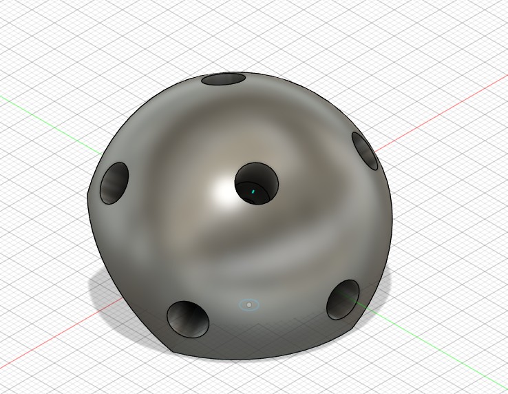
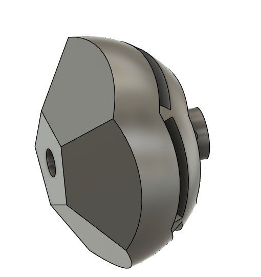
The vertices would be 3D printed. I made a simple 3D model of the vertices in Fusion 360. It consisted of a sohere cut at the angles needed, with holes for the rods to fit in.
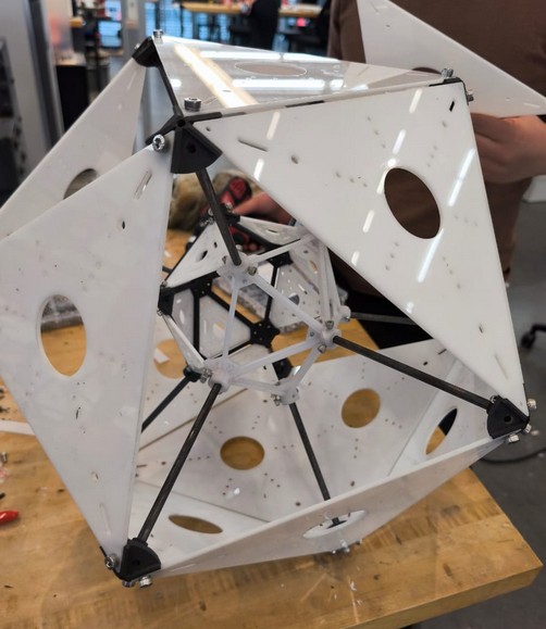
It looked nice to be honest, but I had to know it was too good to be true. Surpringsily, we did manage to make the enitre outer structure, but it was very unstable and attaching the last few rods required a lot of wiggling that I knew would be impossible when thinking about the mechanism inside.
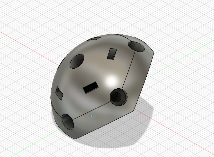
This brought me to the next idea, which was redesigning the vertices to be two pieces that would clamp down on the rods. This way, it could be assembled without needing to wiggle anything out of place. Simultaneously, the rest of the team worked on figuring out the mechanism and the mount for the electronics.
Both of these can be found in this file.
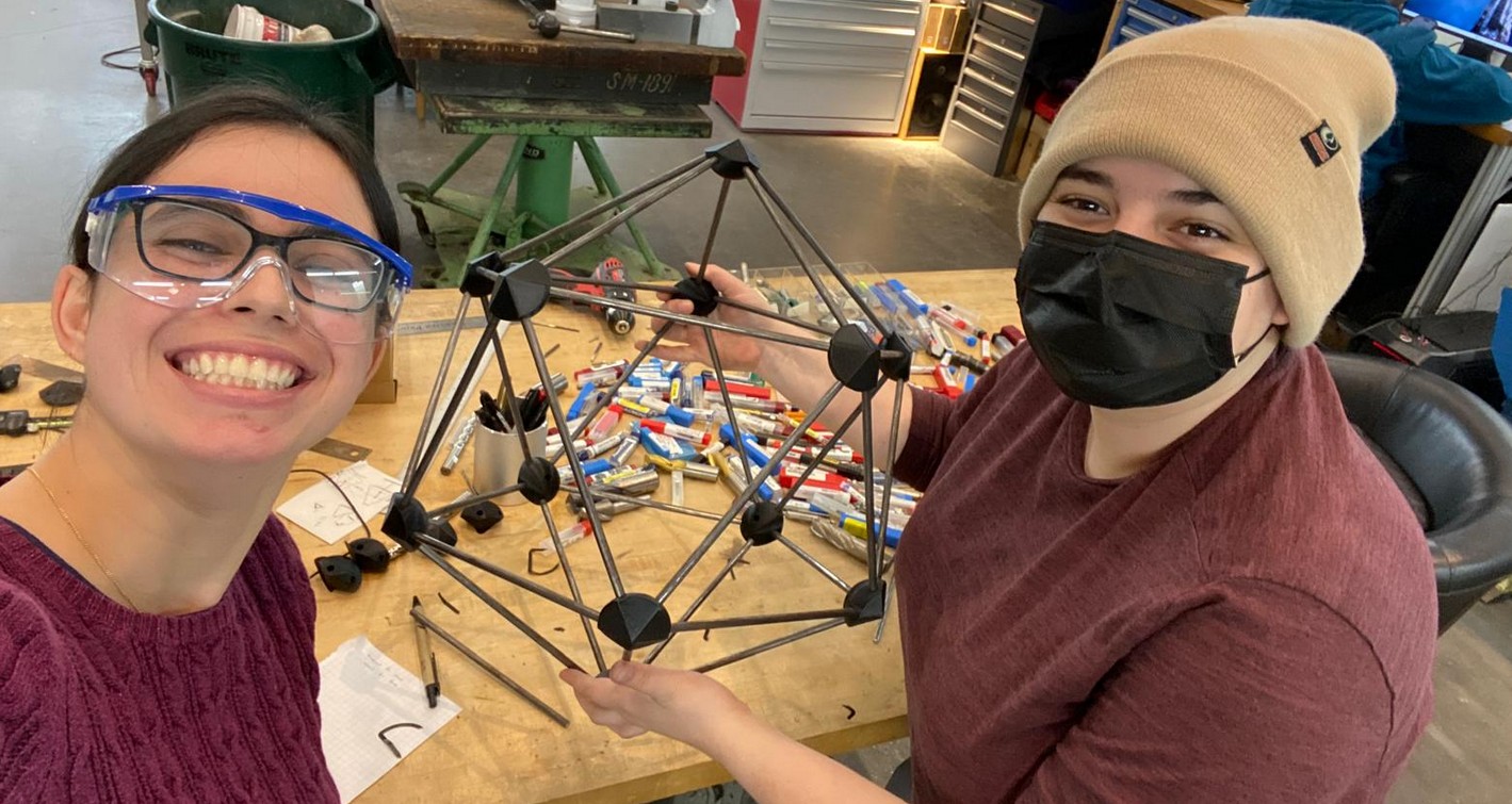
After printing the new vertices, we managed to assemble the whole outer structure without much trouble. It was way more stable and easier to assemble. However, every team was having issues with this vision. The electronics team needed something different to mount on, the mechanism subteam needed a unit that could be more easily assembled for their simulation. Alfonso told us our issue was thinking of it in terms of outside to inside. This cause a complete overhaul of the design, starting again from scratch.
We made a unit volume for everyone to work with. As long as everyone stayed withing that unit of volume, I could design around it and have something that fit everyone.
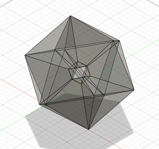
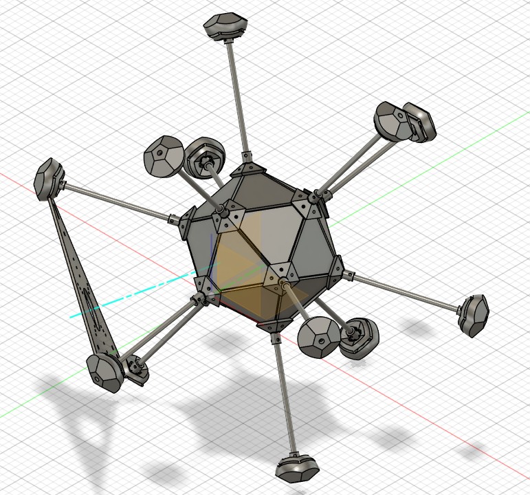
I changed the idea of using rods everywhere to thinking of solid faces that were also providing the structure. I still did not want to 3D print the whole thing, becaus eit would be very time intensive.
I changed the idea of using rods everywhere to thinking of solid faces that were also providing the structure. I still did not want to 3D print the whole thing, becaus eit would be very time intensive.
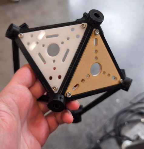
This outer vertices then became two layer to clamp down into a flap surface, and be joined with rods back to the inner core.
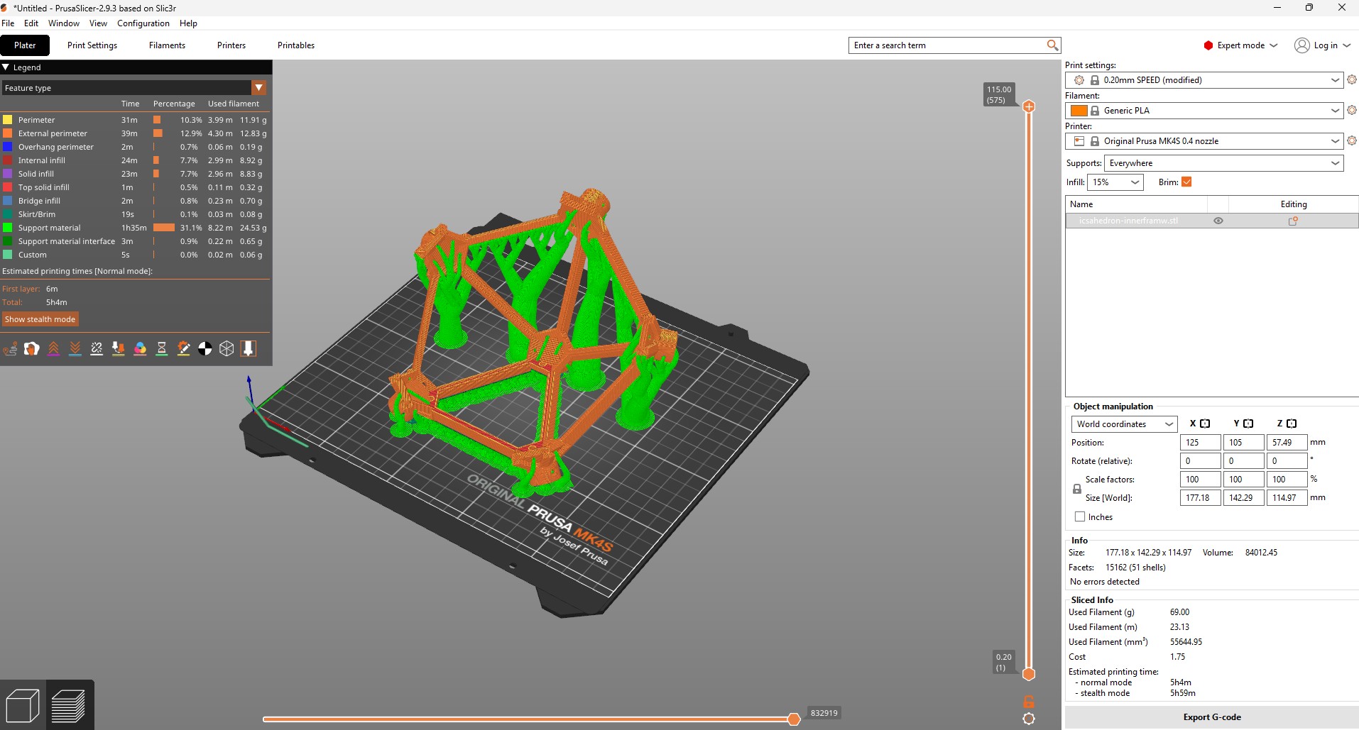
The next day, however, Alfonso recommended the inner frame be one solid piece. Because of the size, I decided to make it two halves though.
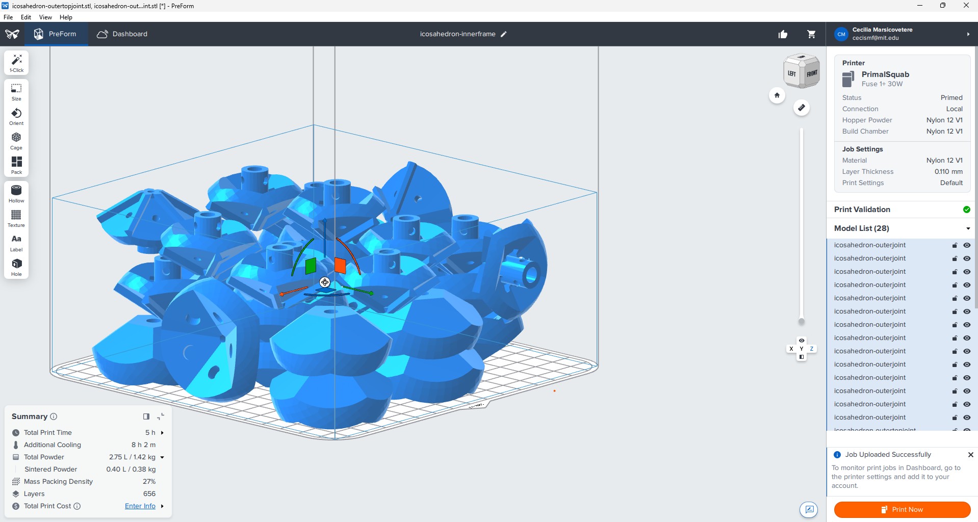
I printed the outer joins and the inner frames using the SLS Fuse 30W + machine. This fuses nylon together using a laser. its very fun.
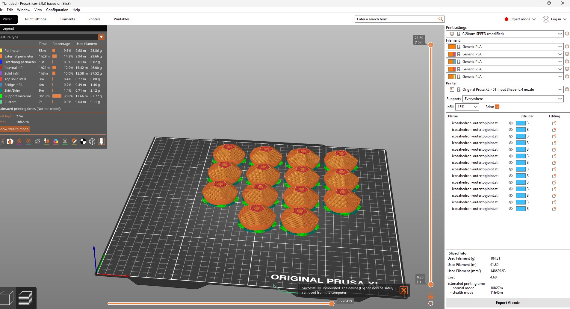
We also printed everything in PLA just in case, to keep building while we waited for the longer prints.
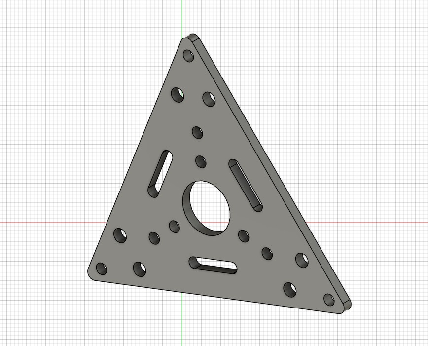
We designed the inner traingles with a lot of holes, since we hadnt finalized the mechanism or the PCB mounting. So many holes just gave us options when the moment came.
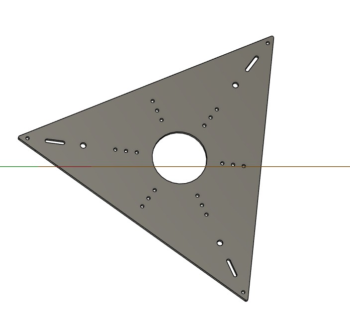
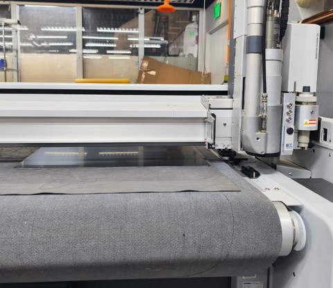
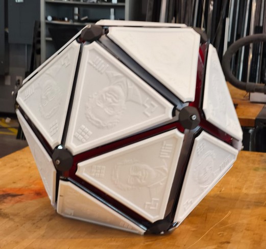
The outer traingle consisted of two parts. One would be where the faces would attach and it would be the one part that moves. We cut this one in the Zuun router in a metal composite
The other part of the triangle was acrylic, and it would hold the mechanism in place.
We started manufacturing and assembling, to give the rest of the team a better idea and have an actual structure to actuate for the mechanism tests.
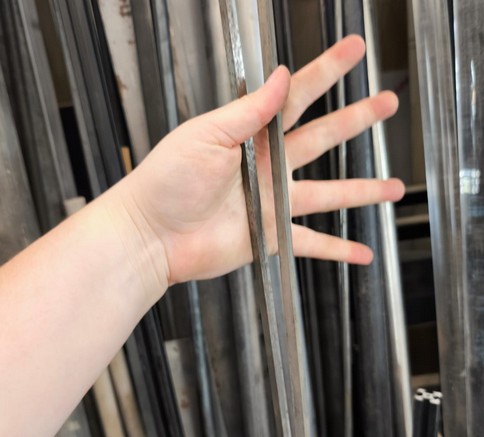
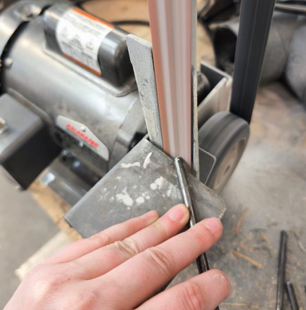
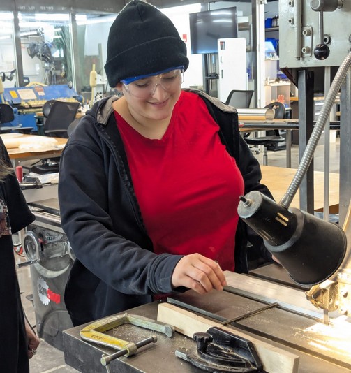
I also cut and grinded the rods at various moments.
Eventually it was coming together.
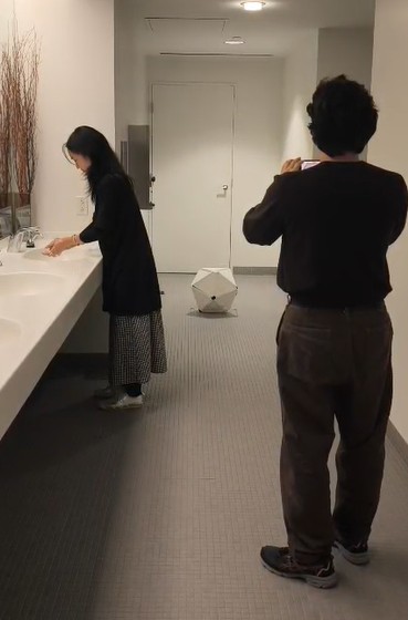
The final assembly and mechanism design I stepped back, mostly assisting when needed but no longer taking on any bigger role. Other than my acting. I was hauling that fake neilbot everywhere to make our beautiful film. Have an exclusive BTS of one of the most iconic scream queens.
All in all, a lot of work a lot of fun a lot of triangles I am done with them.
CAD Files: