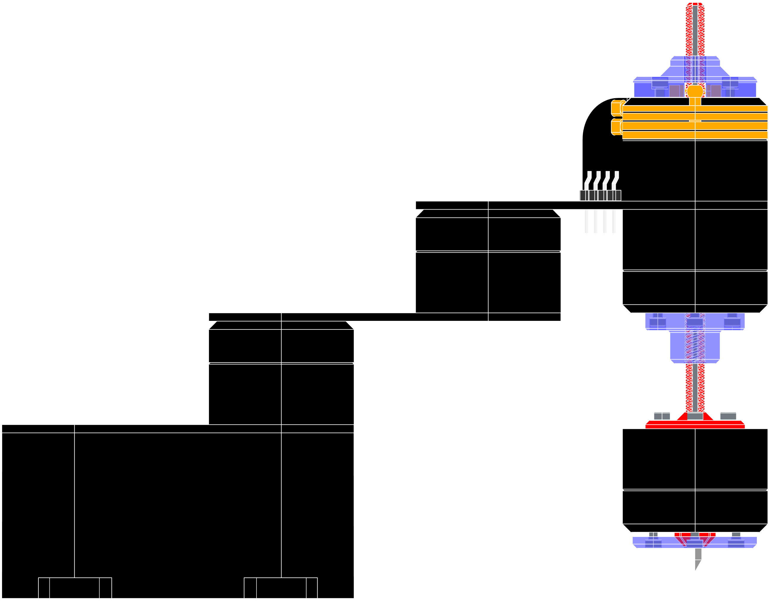
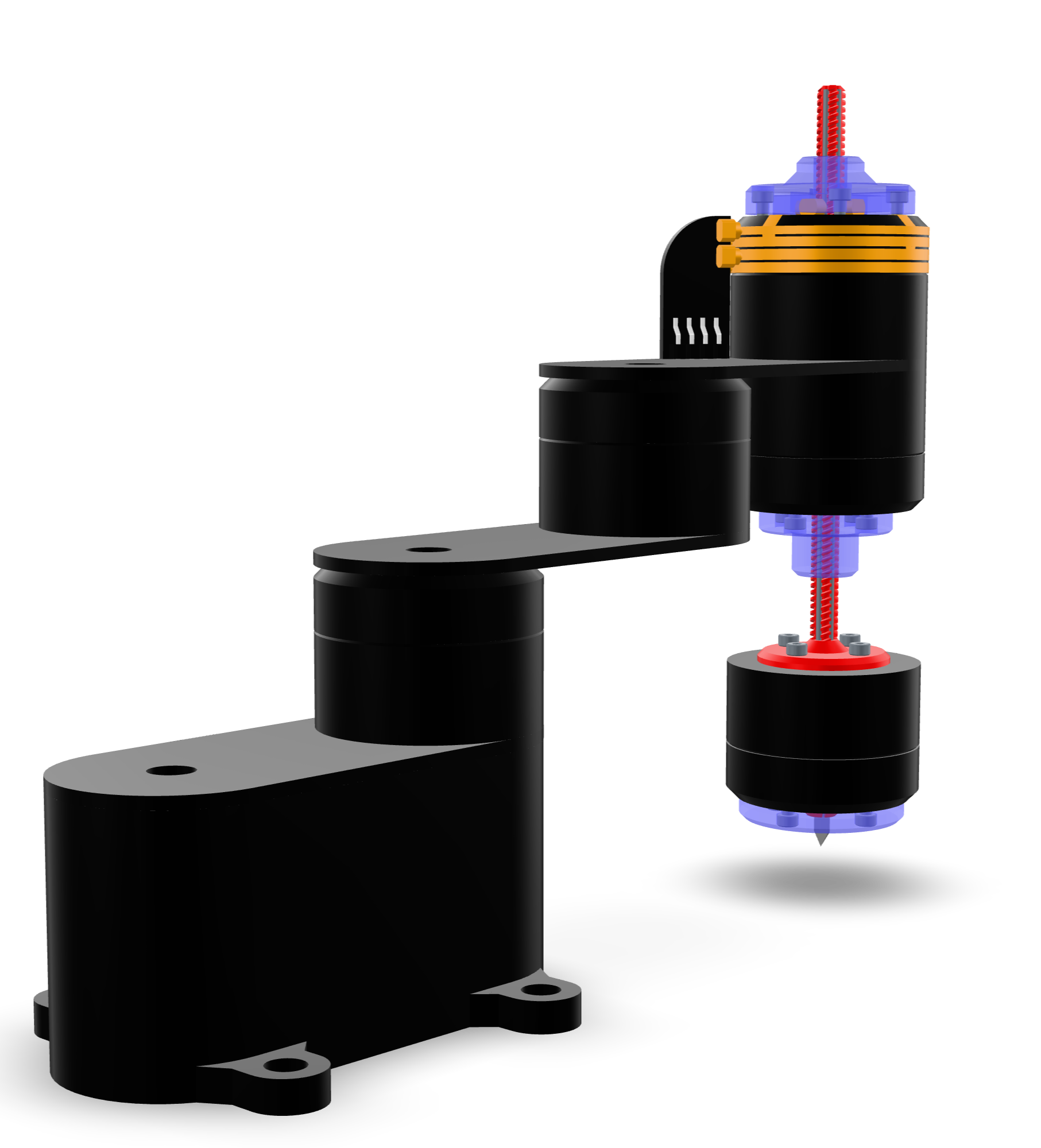
CAD assembly
The bot was modeled in Ondsel ES.
 It's been a really enjoyable exercise in system integration.
From Z to RZ
Baksi 2 only has one motor on the Z-axis, so the tool always rotates when it moves up and down. That's not necessarily a problem for 3D printing or PCB milling, but it is a problem for the pick-and-place tasks that robot arms are known for.
Baksi 3 will get a second motor, to form an RZ -axis (see the RZ-axis page.)
Tiny tool changer
I'm putting my own spin on the SCARA RZ tool. The basic idea is that the RZ-axis is a lead screw that also has straight slots cut into it. It's held by two BLDC motors. One motor has a regular nut and the other has a nut with straight slots. With this configuration we get independent translation and rotation (see the RZ-axis page).
To change tools, you lower the lead screw until it falls out! So the tool changer is free, and it takes up no space on the bot.
But the tool rack needs a lever that raises the tools, so that Baksi can grab them. The bot itself can't move vertically while there's no tool installed.
System integration
But how will I route power and data to the end effector?
 With pogo pins!
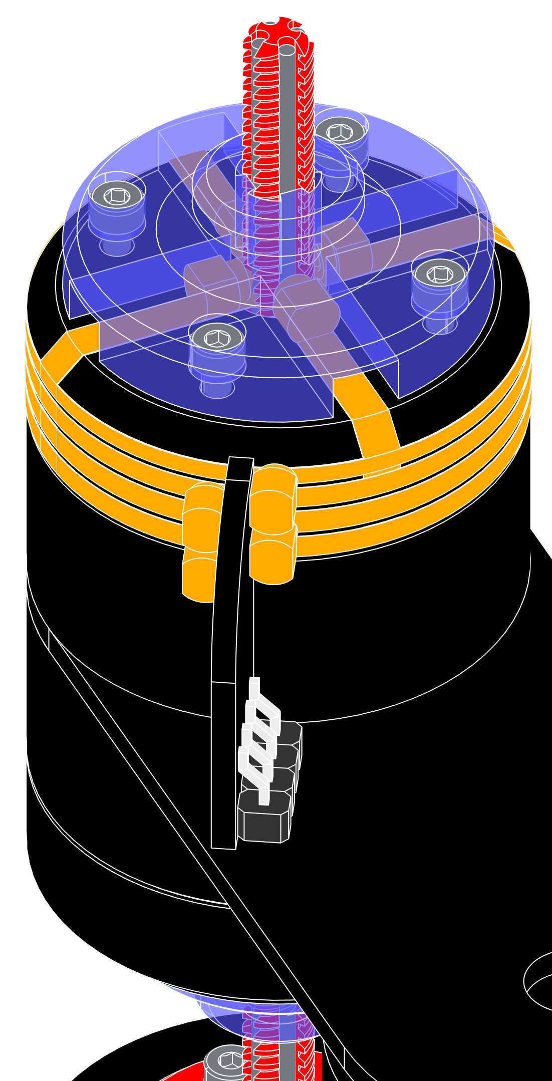
I will 3D print the RZ lead screw and stiffen it with four steel rods. The rods carry power and two data lines to the end effector.
Then I'll use pogo pins to make electrical contacts between moving surfaces. Four pogo pins for the sliding lead screw and four pogo pins for the rotating BLDC motor. Wrapped around the motor is a 4-layer flexible circuit made of alternating layers of copper foil and Kapton tape.
The result: A slip ring that takes power+data up from the motor control board and connects it to the lead screw. The lead screw then carries the power+data through the motor and to the tool:
Design files
You can examine the CAD assembly more closely in the online model viewer:
 It's almost an elegant design, but not quite. I don't like the upright PCB with the pin header. This exposed slip ring design may work, but I'd like to design another one that fits completely into the base of the motor. A clean and simple look is all-important to me. And if I don't want to wear out the PCB tracks, carbon brushes might be better than pogo pins, although they would create dust.
Download CAD assembly (128 MB)