Harmonic drive
Outcome
A harmonic drive that you can make in a Fab Lab! Video from Vineet Padia.
This design is by the Youtube user ZeroBacklash. I bought the files for €4.99 and I can recommend this harmonic drive if you're looking for a strong and precise actuator with no backlash. They also have a bigger Nema23 version. Harmonic drives are ideal for things like robotics, rotational axes on CNC machines and telescope mounts. If you buy the files, please take care to not post them online, as per the design license.
The harmonic drive that I printed on the Ultimaker 2+ here in Ísafjörður didn't quite work, but Vineet was able to print a working unit on a Prusa printer at MIT. I guess I need to tune our printer, it should definitely be able to do this.
Vineet reported that he can't stop the harmonic drive with his hands. He tried to measure the torque, but the motor twisted the mounts that he had made. Now he's using this harmonic drive actuator to turn a hydraulic ball valve. The ball valve needs a lot of torque, so this solution is perfect.
Attempt to replicate an existing design
Vineet Padia expressed interest in using my BLDC-based robot module in a project. He wanted more torque than an ungeared BLDC motor can provide, so I'm looking into a gear reduction that can be made in a Fab Lab. No backlash would be preferable, and that means a harmonic drive. During the Fab Academy, Neil also challenged me to make a harmonic drive in the lab:
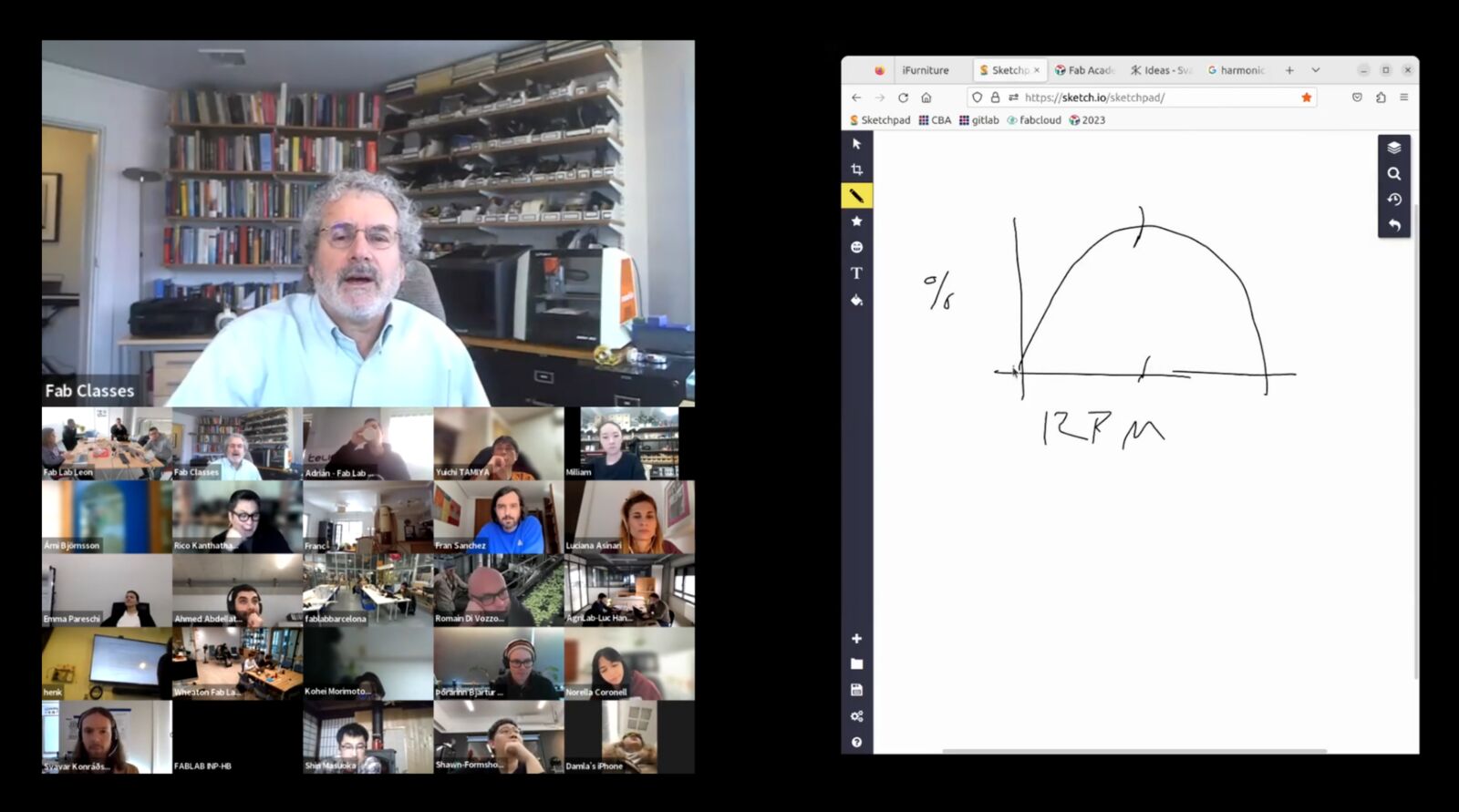 Video: Neil Gershenfeld explains the torque curve of BLDC motors, which is the reason why high gear ratios are necessary in robotics.
Several people have posted their 3D printed harmonic drives on Youtube, but they have typically been wobbly and fragile. The best one I've found is the ZeroBacklash Nema 17 harmonic drive, which I will attempt to replicate here.
I paid €4.99 to get the STL files and links to buy the bearings.
I 3D printed the parts on an Ultimaker 3 using red PLA.
The printer seems to be a little bit clogged, so the plastic line that it laid down was a tiny bit narrower than it should be. This resulted in the parts being too small, and the teeth slipping. I need to prints the parts again and possibly play around with tolerance settings in the slicer.
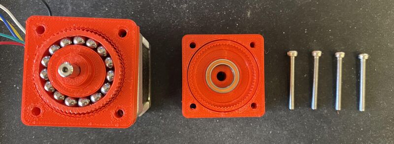
I printed the parts again in grey PLA and now they fit much more tightly together. I couldn't fit the grey flex spline into the circular spline, so I had to use the red flex spline:
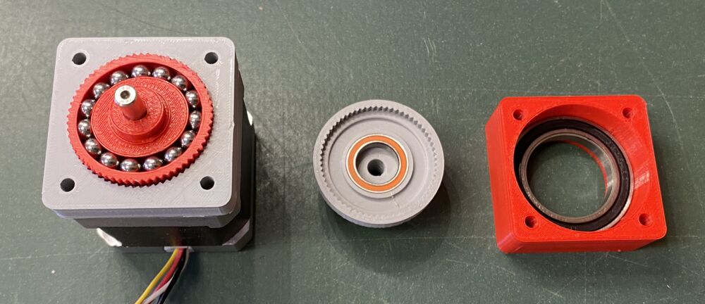
Here it is assembled:
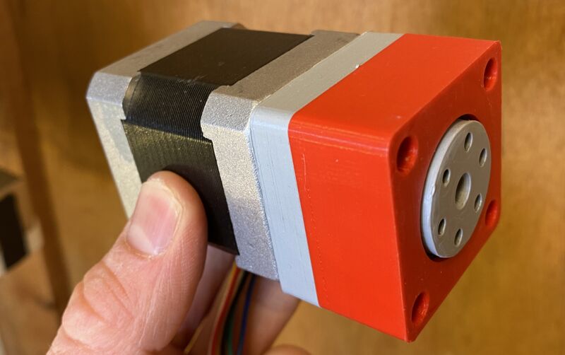
I connected the stepper motor to a driver and turned it:
The axle turns but the output does not. The red flex spline center must be slipping on the axle.
As I examined the grey parts I discovered that I had accidentally printed them with at the extra fine layer height of 0.06 mm, which is unnecessary and resulted in worse quality. I printed the flex spline and center a third time with the normal 0.15 mm layer height.
The spline flexes! Never mind the noise for now. But it's not 'walking' along the teeth of the circular spline. That's a problem.
Even without the outer casing, the output spline is not rotating. The axle slips and rotates a bit every now and then.
I only have stepper motors with cylindrical axles at the lab. This 3D printed harmonic drive is designed for a stepper motor with one flat side on the stepper shaft, so that it doesn't slip on the shaft. I wonder if a more secure attachment to the motor shaft is all I need to get the harmonic drive to work. Here's the STL in Matt Keeter's fstl viewer:
 This is the piece that goes on the motor shaft.
Vineet also suggested that there might be a problem with the gear profile. A harmonic drive has a different tooth profile than the standard involuted gear profile. But this flex spline is neither:
 It turns out that the tooth profile is very simple and not the one used in harmonic drives. I do understand that choice, given that these features are at the limit of what an FDM printer can resolve with a 0.4 mm nozzle. At this small scale the teeth will always come out similarly rounded when printed, no matter what you do in the CAD model.
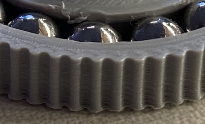 FDM 3D printed flex spline. The center part has chipped where I inserted the ball bearings.
Vineet printed the harmonic drive using Durable resin on a Form 3 printer and got more promising results:
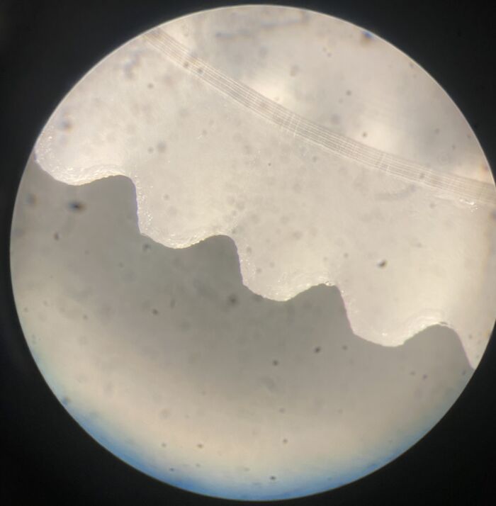 Image from Vineet Padia.
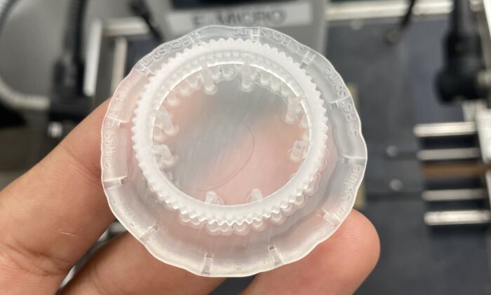 Image from Vineet Padia.
I mailed him the bearings that he needs to assemble the gearbox. Remote collaboration on physical designs is slower than in software, but it helps a lot when you have the same inventory.
The SLA printed harmonic drive hasn't been assembled yet, but the one that Vineet FDM printed works great!
Next steps
My hope is that I can learn from this design and make a smaller harmonic drive that fits onto a tiny gimbal motor. I see two main problems:
- I'm using outrunner gimbal motors, which means that it's hard to find a stationary point to attach the gearbox to. Maybe I'll just use long bolts and fix the gearbox to the PCB underneath the motor.
- The teeth in the Nema17 harmonic drive can't be any smaller using a standard 0.4 mm 3D printing nozzle.
Resin casting is probably the way to go to get sharper and more precise details in the plastic parts. The Guerilla guide to CNC and resin casting provides inspiring examples. I jumped through several hoops to get the tooling board, molding silicone and high-performance polyurethane resin that Michal recommends. I've made a nice silicone mold, but I haven't got the hang of getting the bubbles out of the resin yet.
Resin printing might also be an option for the harmonic drive parts, expecially with a high performance resin like Ultracur3D® RG 1100 or even the ceramic-filled Ultracur3D® RG 3280. The ceramic particles might provide better wear resistance in addition to making the stiffest 3D printing resin I've come across, by far.